Sebastiaan
-
Posts
338 -
Joined
-
Last visited
Content Type
Profiles
Forums
Events
Articles
Marionette
Store
Everything posted by Sebastiaan
-
Regularly I get frustrated. Very understandable.
-
Well I sometimes am irritated when people post their frustrations with exclamation marks and capitals. Maybe a more polite approach to the developers would be in place. Shouldn’t have posted that in public. But too late I already did.
-
Edit : Sorry wrong topic
-
Glad to hear the issue is being addressed. This is one feature that excited me when it was announced on teaser Tuesday. So i’m Looking forward to improvements! Thanx Btw in my file just about every action took several minutes to complete. Creating, moving and deleting the schematic view.
-
I am principally against the use of DLVP’s for raked trusses. I like the workflow of displaying views of the 3D model with 3D labels and or data tags. I was looking forward to using schematic views as one way to display raked trussing. However at it’s introdiucion it does not function as it should. Seems as if it is designed to only work properly with one piece of truss. And it does not work with hanging positions. Which is cracy cause vwx had lured us into working with hanging positions especially since Braceworks.
-
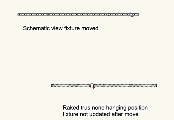
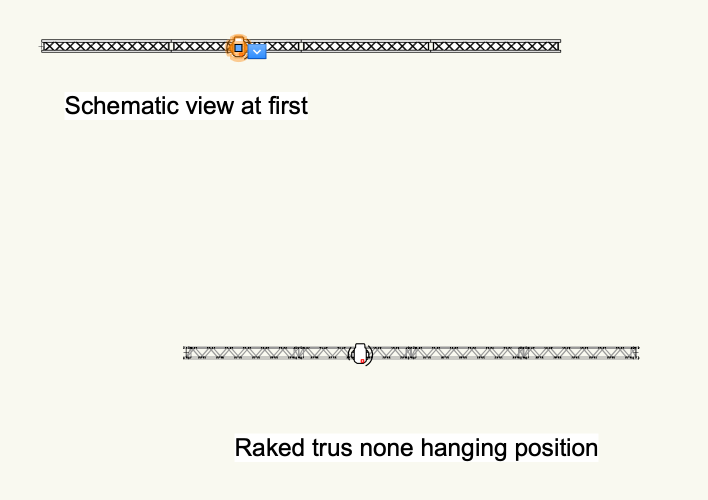
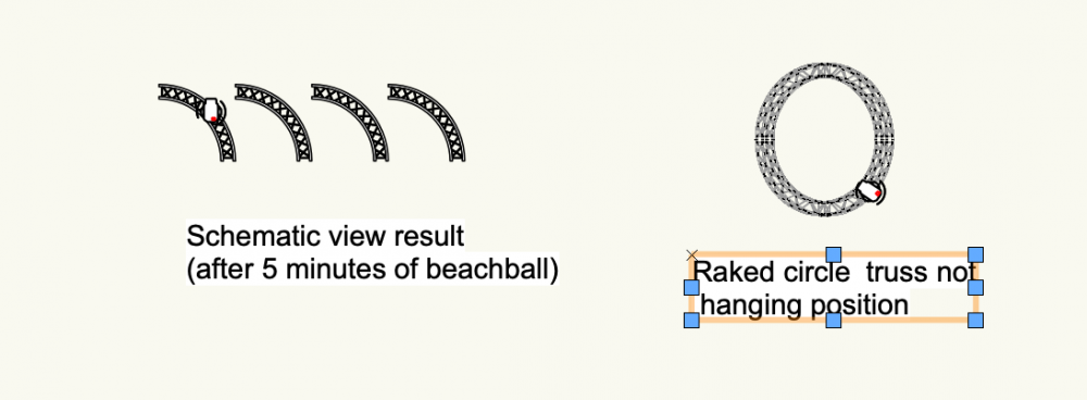
I just tried a straight truss 4 pieces of interal 3mtr and one lighting instrument. If I move the instrument in the schematic view, the instrument in the raked truss does not move accordingly Then a schematic view of a non hanging position with a circle truss and one instrument Edit: test file attached Untitled 1.vwx
-
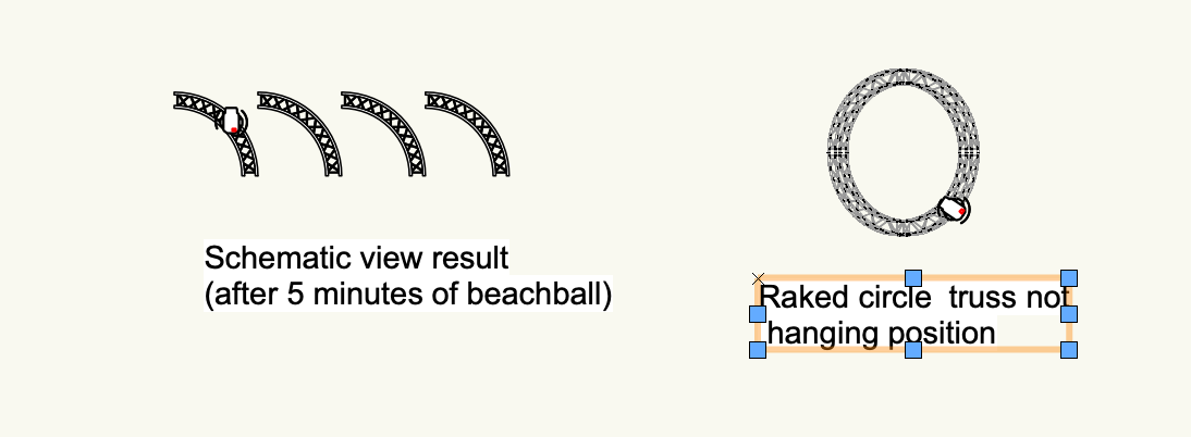
Hi Thanks for your reply. I tried not creating a hanging position with a eurotruss circle. By just selecting the pieces of the circle. And this resulted in all the cuts of the circle displayed next to each other in the schematic view instead of in a circle config. I don’t mean to be a smart ass or anything. But the whole workflow of vwx and Braceworks revolves around the use of hanging positions. How could this great new feature not be designed to work with hanging positions?
-
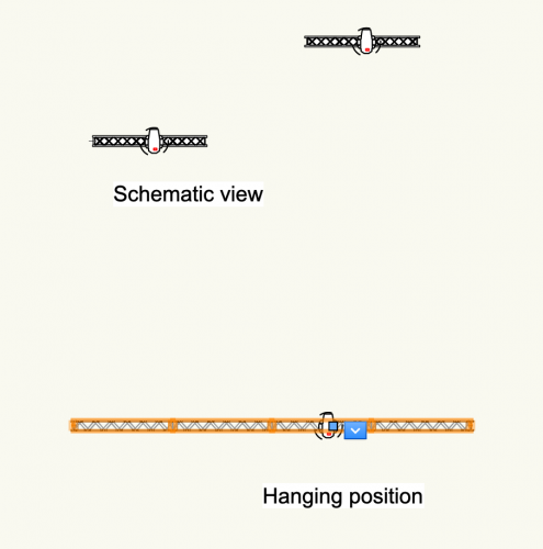
I just did a quick little test for schematic views. I created a hanging position from 4 pieces of truss.And 1 lighting instrument. I choose to use geometry for the hanging position. Creating the schematic view takes multiple minutes of beachball to complete. Once the schematic view is there only 1 out of 4 pieces of truss is displayed in the schematic view. (the one that has the instrument attached.) Moving a schematic view takes another couple of minutes of beachball. I can not rake a hanging position that has no instruments attached unless I check draw 3d only. But checking draw 3D only makes the schematic view not visible. Deleting a schematic view takes another couple of minutes of beachball. Can this be looked at?
-
Grouped 3D label flips when instrument is plan rotated
Sebastiaan posted a question in Troubleshooting
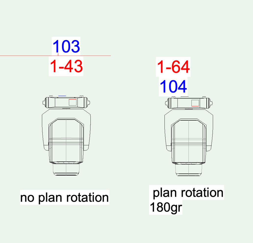
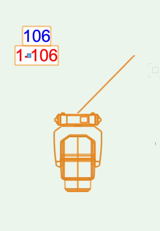
Hi, A problem that I already found in v2019 and just tried in v2020 and still persists. When the fields of a 3D label are grouped in the 3D Layout then a problem occurs when the instrument is plan rotated with a value between 90 and 270 degrees, then the 3D label flips. Flipping the legend from the OIP does not resolve it. See attached screenshot. Can this be listed as a bug?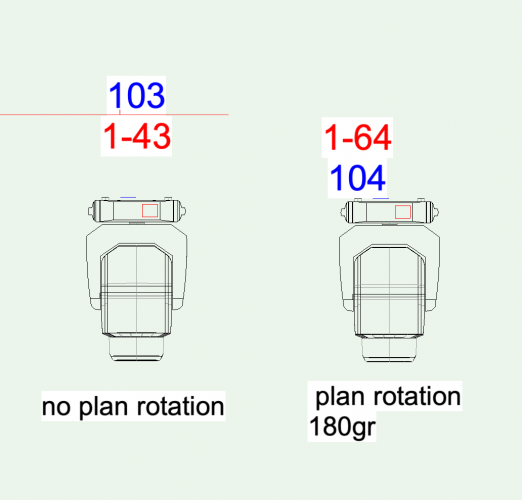
-
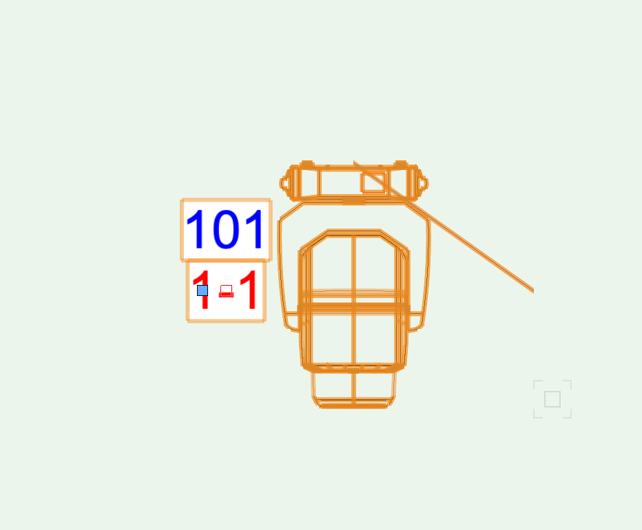
Hi, When the fields of a 3D label are grouped in the 3D Layout then the leader lines do not follow the 3D label. This was already the case in 2019 and just tried v2020 and the same behaviour is present. see attached screenshot. Also the 3D label can not anymore be moved by using right click:"assign label legend properties to selected" In 2018 it was passible to move 3D labels in this way. Can this be listed as a bug? By the way, I would love to have a simple checkbox to turn leader lines off.


-
[3D Label Legend] Leader Lines
Sebastiaan replied to Charlie Winter's question in Wishlist - Feature and Content Requests
yes please, also in grouped 3d labels the lines jump in all directions when moved. Still present in v2020 -
DWG export of rotated lighting instruments works properly now. Thank you developement team!! DMX patching is a pleasant surprise too!
-
2020 Teaser Tuesday - Schematic Views - Vectorworks 2020
Sebastiaan replied to JuanP's topic in News You Need
Finally! I too have asked for this many times. Thank you very much! -
I personally think the check marking should be done in a second pop up window. So the main spotlight numbering window only shows the desired and chosen fields. A + and a - at the bottom of this window to add and remove fields. Also no highlighting untill a field is actually clicked on.
-
Oh yes absolutely it all ends up on paper or PDF eventually! Just the way to it is different. Personally I am principally against this use of DLVP’s. I believe the model should be in 3D as it will be in real life and we need techniques to present that on sheet layers. Or to share this with others (perhaps non vwx people). Not the other way around. But I might be a minority.
-
I use viewports in 3D view (mostly Front) to present things that are built in 3D in real life. Data tags and 3D labels make it possible to present information with it like in 2D. It may be a little more work in making viewports, but it saves time on drawing your plot twice. A sheet layer with front views of booms/ ladders and or scaffolds is a plot too isn’t it?
-
Draw it in 3D and present a font view of it on your sheet layer. Maybe OpenGL or hidden line if you need it to look more clear. Use 3d labels or data tags if you need numbers in your plot. I have not drawn a 2d plot in years. There is no need to anymore
-
There is no problem importing Sketchup if you import an older version sketchup file. For som reason the newest version import never works. Download 2017 or 2018 files from 3D warehouse and you are fine 😎
-
OpenGL Graininess surrounding objects
Sebastiaan replied to Sebastiaan's question in Troubleshooting
@ASagatovVW @Kevin McAllister Thank you! That was the trick. It was on JPEG swapping to PNG solved everything. Thank you!!! Now to re publish 6 files 😉 -
OpenGL Graininess surrounding objects
Sebastiaan replied to Sebastiaan's question in Troubleshooting
If can’t be class related. I opened the old file without changing anything to it. So all class settings should be exactly the same as back in May. Also i already updated so sp3 directly when it came out in March. Not sure when sp3.1 came out but did that one straight away also. I’m stumped too! -
OpenGL Graininess surrounding objects
Sebastiaan replied to Sebastiaan's question in Troubleshooting
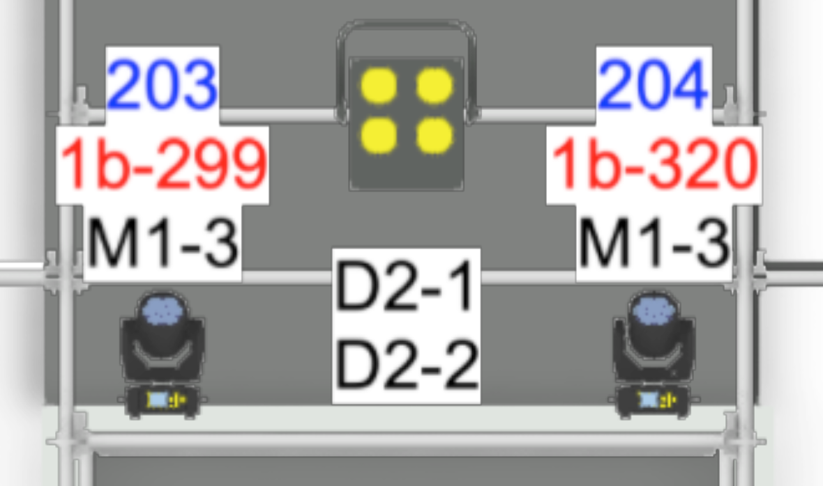
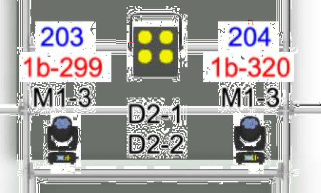
Just opened a file from a project in may and updated the viewport without changing any settings see screenshot below: Ans then below screenshot from the PDF that I made then from the exact same sheet layer with exactly the same setting. Find the differences....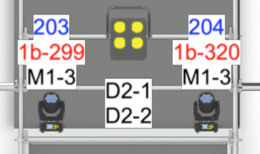

-
OpenGL Graininess surrounding objects
Sebastiaan replied to Sebastiaan's question in Troubleshooting
The thing is that the projects I did in May and June did not show this distortion. I usually print my plots at around 1:100. So something changed since then, I just can’t figure out what. Have had numerous reboots and program restarts also it happens in every new file that I start now. The fact that the label fill of the OpenGL label renders fine on your machine makes me think there must be some setting somewhere that triggers the behavior. However strange it is that it is only visible on a sheet layer. I never had to increase the setting to get acceptable result. Something changed somewhere. -
OpenGL Graininess surrounding objects
Sebastiaan replied to Sebastiaan's question in Troubleshooting
Thanks for your reply, alpha channel is turned on. Attached is a new file with the issue replicated. Also a screenshot of the issue. This is by the way only happening on sheet layers. Hope you can see whats's wrong Test OpenGL.vwx
-
OpenGL Graininess surrounding objects
Sebastiaan replied to Sebastiaan's question in Troubleshooting
Unfortunately that is not it. It is already set to 300 -
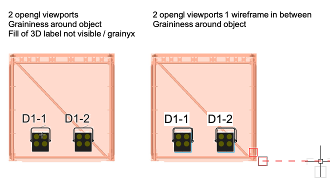
Hi, I am currently having a weird open GL thing. I have three viewport on top of each other on a sheet layer. On the bottom is a opemGL frontview of a stage. In the middle is a wireframe sheet with Spotlight lights with 3d labels. And on the top is a openGL Spotlight light without the 3d Labels. This way my labels and lights always lay readible on top of any geometry in de stage. I have used this workflow for a couple of years and also on several projects this year without issues. But now all geometry in the top viewport is surrounded by white grainy smutch. See attached screenshot. Opengl is set to high quality and anti aliasing is turned on. The issue is occuring in 6 different files at this moment. They where al new 2019 files that I have imported layers + objects in. I am on VWX 19 SP3. Anyone have any ideas?