line-weight
-
Posts
3,755 -
Joined
-
Last visited
Content Type
Profiles
Forums
Events
Articles
Marionette
Store
Everything posted by line-weight
-
 I hereby submit my entry. Screen Recording 2023-01-02 at 22.55.30.mov möbius.vwx
 -
@jeff prince can you post the file for examination?
-
@Benson Shaw as I'm sure you're fully aware the difficulty with your method is getting the two halves to join mathematically exactly, that is with all the curves meeting each other at a properly tangential transition. And you can get pretty close by telling each loft to pass through the same profile at the same point, but the lines leading in from each side don't arrive at that profile at exactly right angles. I'm often posting a link to this thread and particularly the contributions from @axhake because it addresses problems that always arise whenever you're attempting this sort of thing with NURBs and lofts or extrude-along-paths. And the solution there is basically to accept that the object will be faceted rather than truly curved. But you have some control over the number of facets and can make sure things do actually meet exactly.
-
Extracting an edge from a solid that the "deform" tool has been used on seems to produce a NURBs curve where the XY plane of its "normal" rotates along its length. (When I say "XY plane of its normal" I'm probably using technically incorrect terms. But if you activate the working plane tool and trace the cursor along the NURBs curve, it rotates) I wanted to see if I could exploit this using the "extrude along path tool". I did manage to produce some twisted strips. However, I can't see any way to directly manipulate this property of a NURBs curve, and wasn't able to make a circular NURBs curve whose "XY plane of its normal" rotates by 180 degrees from start to finish. I don't think this kind of manipulation is possible. But, NURBs curves and the EAP tool are both very poorly documented in VW so exactly how they each work continues to remain a mystery to me and I end up resorting to trial and error.
-
I should probably experiment a bit more with that but yes the main concern is about how easy it is to make changes further down the line - compared to, say, a solid addition that I maintain such that I can edit and move the various elements within it.
-
Exactly as @zoomer says, the way the BIM model is built up should reflect the way the building is built up. The more closely they are connected, the easier it is for the logic of connections to automatically follow. A building might have 2 or 3 types of wall core/structure. Maybe it will also only have 2 or 3 types of external wall finish, and it might have 5 or 10 types of internal wall finish. But these all overlap with each other, so the number of possible combinations of external finish + core + internal finish becomes larger than any of those numbers, and most of us I'm sure end up with 10s of wall styles with elaborate names, for each project, by the time you get to a certain level of detail (or you just give up on wall styles altogether). This is going a little bit off topic but the same reasoning is relevant to the question of whether things should be merged in section or elevation. For example a common frustration is joint lines appearing on elevations where they shouldn't. Firstly VW should be able to understand that if the materials are the same, and the elements are coplanar, there's no joint line. And it is kind of programmed like that already. But also, all these potential joint lines in the external finish of a model, most of them are only there because of the logic behind building VW walls which says that junctions in the external finish generally correspond to junctions in the internal finish. Walls are concieved as things that span from storey to storey. But constructionally, walls aren't usually like that. The core may span storey to storey - or it might be continuous. It depends how the floor structure is attached, and the sequence of construction. Internal finishes do generally span storey to storey (with offsets for the floor depths). And external finishes very often don't care much about internal floor levels at all. They might span from some point relative to external ground level, to some point relative to the edge of the roof. If the logic of how walls were modelled wasn't entirely based on the starting point of a wall being something from one storey level to the next, then perhaps we could have more efficient methods of applying external wall finishes. And ones that didn't introduce so many opportunities for portions to be 1mm off co-planar. Because by definition the whole thing would be coplanar. This is often where I end up when I finish up with a model where a wall object is used for the core but directly modelled solids are used for internal & external finishes or cladding. It's a pain to have to manually cut wall holes ... but I can draw it as it actually is, and often that's with multistorey portions of walls drawn as one object or group. If I want to look at the building storey-by-storey (isolating each by layer), then of course these large wall cladding objects can get in the way. But... if I am looking at the building storey-by-storey, I'm looking at internal stuff so they can simply be turned off. And for that reason they get classed as external wall finish objects, or maybe they even get their own layer. In any case the point is that in my experience, whenever I start deviating from the way VW expects me to build a BIM model, and I start using more of my own custom classes or layers to control visibility or material or whatever, then I always seem to end up at the same place: things are separated off from each other based essentially on construction sequence. Standard VW objects like walls and floors don't currently allow this. And the "merge with structural objects" tick-box is perhaps illustrative of how concepts have got muddled - or how there's a failure to recognise what "structure" means, in the context of a BIM model and the logic that underpins it.
-
I basically agree with this too.
-
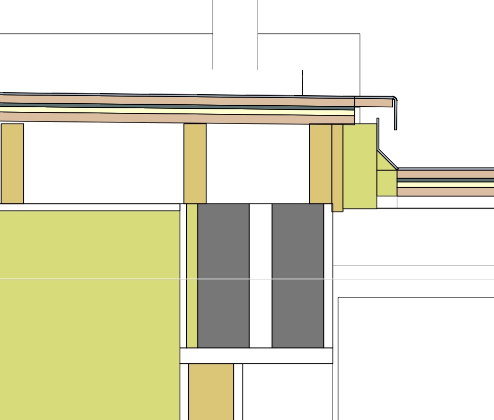
All this sounds very similar to something I've been doing this year. And run into many of the same questions. I don't know Bricscad so I'm stuck with Vectorworks. Here's an example of the quite complex construction, the sectional view is only for my own purposes (so doesn't have to look pretty or even be very understandable by other people) but there are lots of things I'd have to fix in order to make this useful as documentation. For example it's a flat roof which started out as 3-ply roofing felt but then had a fibre-glass roof installed over the top of that. So there are large areas of flat roof, with multi-layer buildup, but with various drip or upstand details along the perimeters. I can model the main part of this roof with a multi component slab or roof face object... but then the perimeter details have to be modelled directly with extrudes. And this is exactly the kind of location where I run into the problem of merging those perimeter details with the top layer of the roof buildup, because fibre-glass is a contiguous material, and I don't want a line at the transition. At the moment each time I reacj this kind of detail, and I want to make it into a "proper" sectin drawing I have various options... - model most of the roof as an eg. slab object (with convenience of multilayer buildup, etc) then make the perimeter as extrudes, and then fiddle about with settings and viewport options and maybe annotations to force the parts to merge where I want them to - give up on using a slab object, model the whole roof buildup directly as solids & use solid additions to "merge" the relevant bits together - maybe use a slab object for the bottom-most layers, and then direct modelling for the more complex outer layers. The best option always depends on the project and what I want to produce at the end and how much I expect to have to edit things once I've modelled them....but sometimes things change and the better option turns out not to be the better one, but I'm too far down the line to change it. More direct control over the merging of objects would save me having to make those painful decisions early in the process (and then discover later that I made the wrong gamble). P.S. producing the clip-cube image above reminds me ... please can we have the clip cube let us see full section detail on its cut plane, ideally just like a non merged section viewport would???

-
In these scenarios, you maybe could use duplicate "materials", for example "between-stud insulation" / "cavity insulation", and "wall concrete" / "footing concrete". I already do something like this under my current approach. Of course this becomes one of those things where you trade off the admin of having multiple materials vs multiple styles. And the balance will be different for different people according to use case.
-
My suggested approach I think could do what you want without you needing to set things up for each component of each wall style - it would be decided by what material each component was.
-
As far as I can see, the biggest problem with all these systems is how to get the raw measuring data converted into a form that is useful in your chosen drawing software, which in our case is Vectorworks. Measuring a wall in great detail, with great accuracy and very quickly is now easy: getting that to appear in Vectorworks drawn in a sensible way as a wall object (with appropriate door and window objects in it) is the tricky bit and still requires a large amount of manual intervention.
-
Having given it a bit of thought, here is how I think "merging" can most usefully happen. This is assuming sections where internal build-up of things like walls, roofs and floors are shown. - There are materials (say, poured concrete, or plaster) that generally exist as a kind of contiguous mass. They are not made up of individual units. - In most cases, with these materials, if I draw two objects made of them, and the objects are immediately next to each other without a gap, I am drawing them as two objects because that's what is convenient to draw, rather than because I want them to appear as separate objects in the drawings. In this case, I'll almost always want them to be "merged" in section (and elevation). - Then there are materials (say, timber framing) that generally exist in the form of individual objects/members that are fixed together. - In most cases, with these materials, if I draw two objects made of them, and the objects are immediately next to other without a gap, I am drawing them as two objects because they really are two objects. Therefore I don't want them to be "merged" in section (or elevation). For example; two timber beams immediately next to each other. I'd nearly always want them to be drawn unmerged because I'm drawing a doubled-up timber beam, not a single timber beam that's the dimensions of the two objects added together. And that distinction is important constructionally. - There are certain materials which aren't exactly "contiguous mass" materials, but are generally drawn as such. For example, brickwork - it's actually made up of discrete units with mortar in between them, but it's not usual practical to model it that way, and in construction sections it's usually shown as contiguous rather than with each individual brick drawn. Sometimes individual brick units might be drawn in large scale sections, where it's important to show it, and in this case the bricks could be modelled individually, or such detail could be added manually in annotation space. - Therefore, in principle, whether or not adjacent objects should "merge" should mainly be determined by what material they are made of. - The existing approach of merging or not merging objects based on whether they have the same fill works up to a certain point for me, because I use "material classes" already, and every component in my model has a material class, and that's what determines the fill it has in a section. So when I want objects of "contiguous" type material to merge with each other in section, I can mostly get this to happen, by classing them the same, and telling VW they are "structural" for the purposes of sectioning if necessary. - However, I'm not given the control I'd actually like, which is to define merging behaviour per "material class" rather than per object via the "merge with structural objects in sections" button. Logical to me is to tell VW what kind of material something's made of, then merging behaviour to happen as a result of this. I shouldn't have to tell it what to do with each object individually. - I don't (yet) use the newly added "materials" concept in VW. That's partly because it doesn't seem yet to be applied consistently to all objects, partly because I haven't invested the time in understanding how to start using it, and what advantages it offers over my current strategy of defining material via class. If some kind of sectioning behaviour can be implemented based around the materials concept, I'm open to adjusting my workflows in order to take advantage of it. - The existing approach of certain objects being called "structural" doesn't make much sense to me, because it seems to mean that non-structural components of things like walls get included, and I don't see in what way it's useful to anyone. Of course, it may be useful to some people and maybe there's a reason to retain it, but I think it should be better named. - In all of this I'd want to stress that it's crucially important that these kinds of sectioning behaviours are solidly reliable, predictable and consistent. It's not just for aesthetics or clarity - the presence or absence of a line between components will often convey important information from a constructional point of view. I don't want to be on a site visit and find something built incorrectly because VW has drawn a section differently from how I told it to. We've already identified that the "profile line" has been messed up in the transition between 2022 and 2023 and there are also ongoing issues with lines appearing in elevations where they shouldn't. This is fundamental stuff and it should be one of the first things to check and double check before releasing any new version of the software into general use. I would be interested to hear where others do/don't agree with me on any of this.
-
Especially these kinds of issues that break completely essential and fundamental things such as elevations or sections. In the 2D CAD paradigm the equivalent would be drawing a line and seeing it disappear or commanding to erase a line and nothing happening. Repeatedly and with no workaround.
-
Yes...which is why it's confusing to call them "structural" objects. But even if they were renamed, say as "parametric building parts", I still don't really see that it's a useful or relevant distinction to make, when drawing a section. When I draw the section, I don't want to tell the reader of the drawing about how objects are generated in my CAD programme. And I don't feel that it matches any particular drawing convention that I'm aware. There are however things that are useful to have control over: - Whether or not certain objects get merged with adjacent objects that have the same fill - A distinction between an outer main profile line thickness, and the thickness of other lines within the section cut.
-
Done!
-
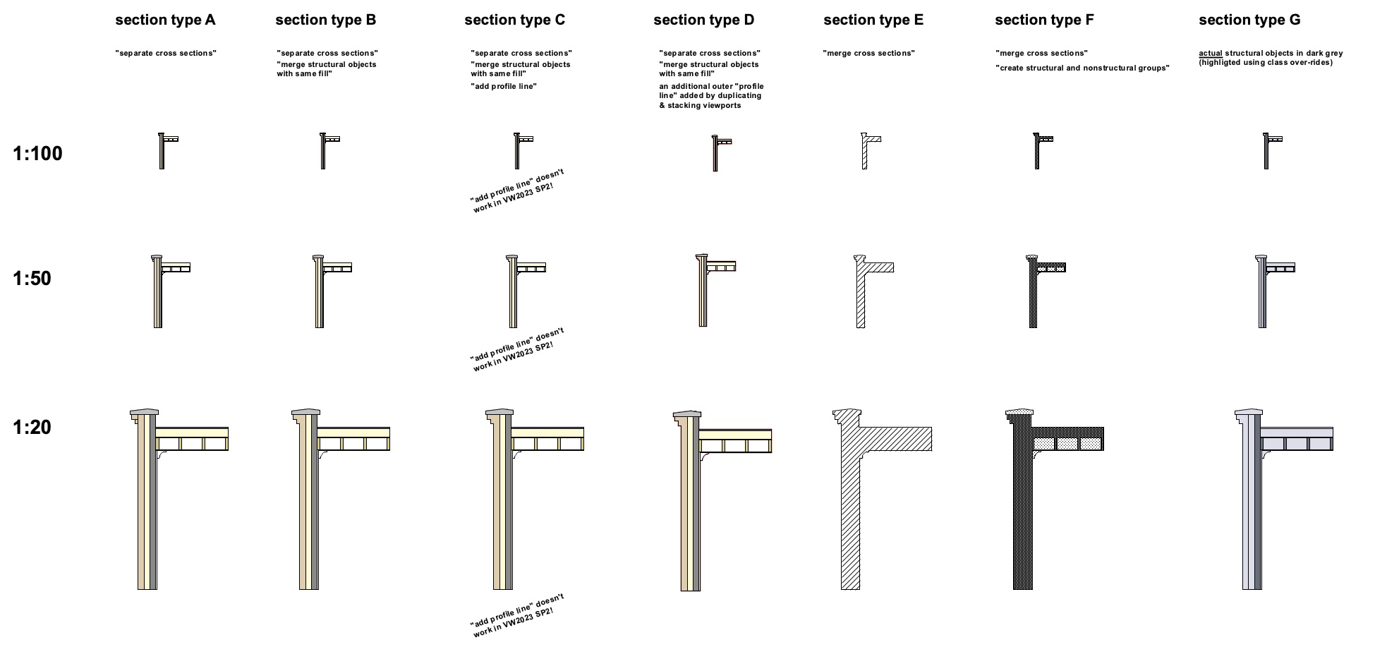
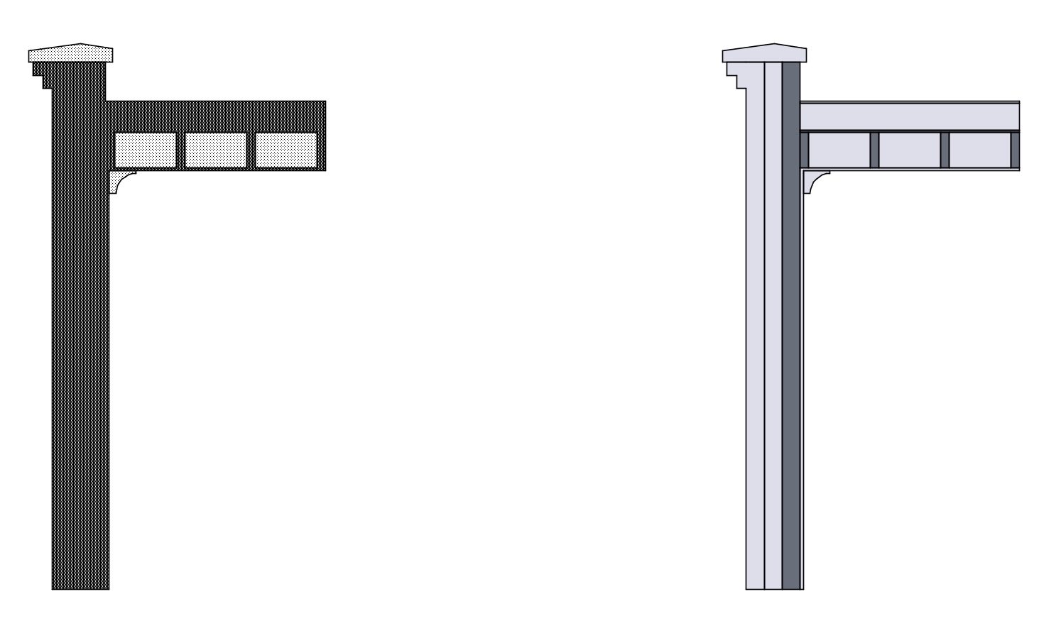
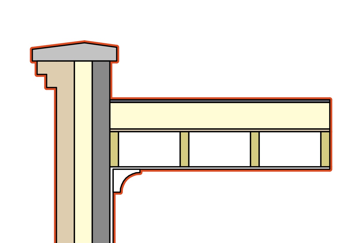
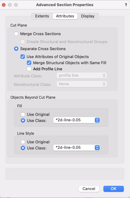
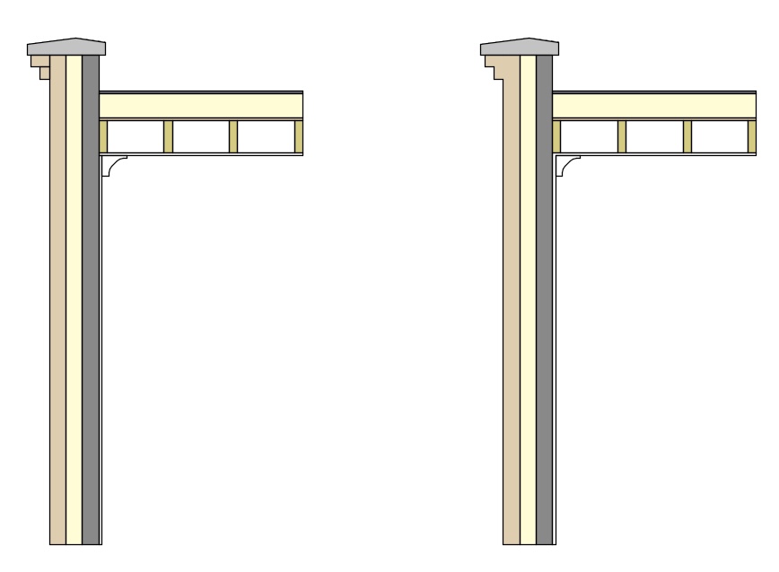
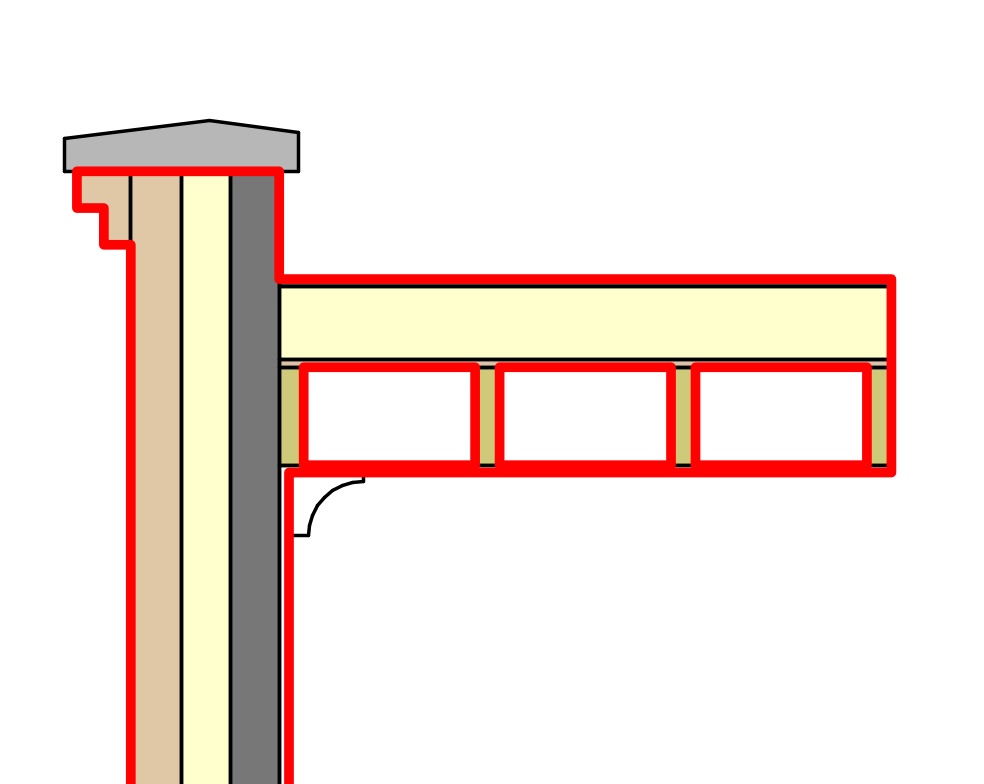
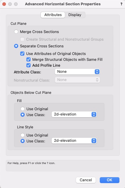
At the request of @Matt Panzer a wishlist item, spun off from a discussion thread. Basically: I think confusion arises around what "structural objects" are, as defined for the purpose of section viewports and the various options in the "Advanced Section Properties" dialogue. But this wishlist item goes a little further I think. I am going to try and keep this concise to start with, partly to stop it being too confusing, partly because I'm running out of time to write this just now. Here's that dialogue box: I have attached a VWX file with this post. It'll probably be necessary to open it and look at it in order for this post to make any sense. Screenshots are taken from it. The array of possible section viewports looks like this: Each of those section viewports is a section through this hypothetical wall/roof buildup: That's a standard cavity wall here in the UK, brick outer skin (not loadbearing), insulation in cavity, block inner skin (loadbearing). I've modelled a kind of decorative brickwork corbel at the top of the brick. The roof is structural timber joists, plywood deck on top, insulation & membrane above. Plasterboard ceiling fixed to bottom of joists. Decorative coving at junction of wall and roof, internally. What I've drawn is just illustrative for the purposes of this wishlist post. Most of my section drawings (in practice) are either - something like section type B where I want to show some level of internal buildup detail, and where the scale is 1:50 or larger. In these examples I've shown material fills as solid colour, but in reality I would usually be using hatches instead. - something like section type E where I don't want to show buildup detail. Anything smaller than 1:50 will usually be like this. Sometimes I might use it up to 1:50 for early stage drawings. Points to make: Note the difference between section types A and B: On section type B the brick corbel detail is "merged" with the brick component of the wall. I'm more likely to want this, than the lines shown in section type A. I've achieved this by telling VW that those extrudes I used to model the corbel courses are "structural objects" because this allows it to merge them with the "structural object" that is the wall. But of course, those corbels aren't in reality "structural objects" at all. What are/aren't defined as "structural objects" for this purpose doesn't make sense to me. Either VW has got some wacky ideas about what's structural (ie holding the building up), or that's just a bad name for that type of object, or there needs to be some additional method(s) of choosing what to merge in sections. Below, section type F on the left shows what VW thinks is and isn't structural. Section type G on the right shows what I think is and isn't structural. Then we come to what the "profile line" is. I actually haven't really used this in real life. I'd assumed it was the outer profile of the whole section...but it seems it's not. A complication is that it doesn't seem to work in VW2023 SP2. So... here's a screenshot from VW2021 to show where it is drawn (as the red line) in section type C : But in section type D I indicate (by using stacked viewports) where I think a "profile line" should be and would be useful, and, I think, fits with a fairly standard drawing convention where the overall section cut line is drawn with a thick line (I've just shown it in red for emphasis) and then the internal detail (also in section) is drawn with a thinner line: Ok, I'm going to leave it at that for now, no doubt multiple subsidiary questions will come up in discussion. I do think the way that sections are drawn (and the amount of fine control given to the user) is really crucial in allowing us to create good, clear documentation from the model with as little touching-up in annotation space as possible. VWsections.vwx


-
When saving as, open the folder from the file comes .
line-weight replied to Ben3B's question in Wishlist - Feature and Content Requests
Me too! Often followed by a panic that I've somehow lost a whole drawing ... and it turns out it got saved into a different project folder. -
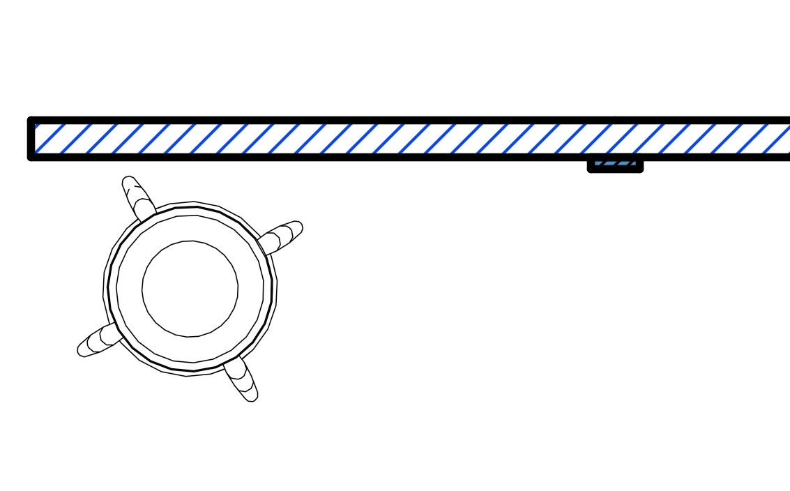
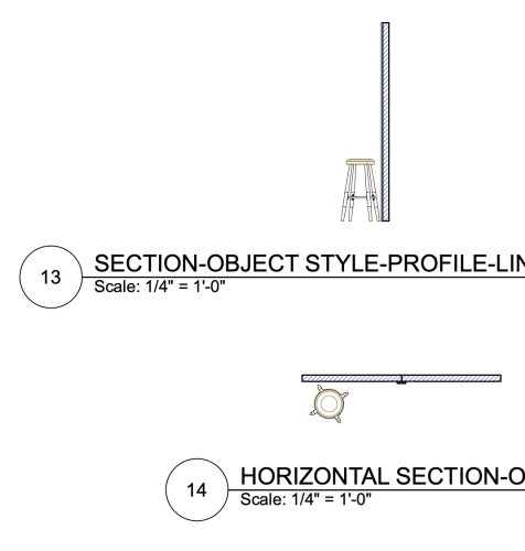
I missed something out, which is that I have a class that's for anything drawn in 2d elevation (ie beyond the cut plane). I have made one called 2d-elevation in your file. Then I set "objects below cut plane" like this: With this result - the elevation of the stool is now drawn in the line type assigned to that class. (note for some reason it's now merged those panels... not sure why that has changed now...) 2022-12-17-HORIZONTAL-SECTION.e2.vwx

-
Layer Scale question - why not just 1:1?
line-weight replied to yasin2ray's topic in General Discussion
Hm, I seem to remember some of these button mappings changing in the past when upgrading to a new version of Vectorworks. As the problem appeared with a change in VW version, does this not suggest that some of the problems are caused by things at the VW end? That selection between navigation types has always confused me a bit, because in the 3DC settings it's listed as an "application command" along with a bunch of other VW tools, suggesting that it is altering something set up within Vectorworks, and yet as you say, there seems no other way within Vectorworks of changing that setting. When I use the 3DC device, it activates the "flyover" tool but these navigation types aren't listed within the flyover tool anywhere. I think in past threads @Luis M Ruiz has been pretty helpful with 3DC problems. -
Can you give any examples in visual form of how it's envisaged that it would be used? What you describe doesn't really match the kind of drawing conventions I'd follow, although of course everyone is different. To me, a section line is a section line - if you start drawing certain sectioned elements in thinner lines then the risk is that it's not clear if they are in elevation or section. The only part of a "cut plane" profile that I might change lineweight for would be glass - that is, the glass in a window but not the frames. If thick lines are obscuring detail then either that detail needs to be drawn at a larger scale, or it needs to be drawn in simplified symbolic form (controlled by level-of-detail). It's true that sometimes fixtures (like wash basins or furniture) can appear sliced in sections where you don't really want them to: in that case I would prefer just to omit them entirely if it would aid clarity. Showing them sectioned but in a different lineweight doesn't really remove confusion.
-
Can I ask what the reasoning is behind this? Because I would say, conventionally in a section drawing, certain elements aren't usually treated differently from others when it comes to what's drawn as cut. I can see certain scenarios where you might want certain things, of the same material, *not* merged in section. It would, in my opinion, be more useful for everything to be merge-able by default, with an opt-out for special things, rather than the other way around. So, something like an extrude has the "structural object" box ticked by default, and the user can untick it if they want. (Or, the box is renamed "don't merge with similar-filled objects in section" and is unticked by default)
-
Not 100% sure about this but I think this merging doesn't work when it's between symbols. If you had several extrudes in one symbol, then I think it would successfully merge them together. I think the same is true for auto-hybrids, and this is one of the reasons I stopped using top/plan some time ago (I now only use horizontal sections) because using top/plan forces you to use auto-hybrids and you end up with "seam" lines where you actually want things to be drawn contiguous/merged.
-
My method for dealing with this is to control section line thickness by class. A have a set of "materials classes" and each of these has a different hatch or fill, but the same line thickness as I want my section line thickness to be. When I use "merge cross sections" (in the advanced properties for the VP) these class attributes are irrelevant and the section line is determined by a special "cut plane" class. When I use "separate cross sections", then each different "material" has its own fill, and is outlined in the same section line thickness. See modified version of your file attached below. I have renamed your classes "FLAT" and "TRIM" as I would name my materials classes. 2022-12-17-HORIZONTAL-SECTION.e.vwx
-
Layer Scale question - why not just 1:1?
line-weight replied to yasin2ray's topic in General Discussion
Is the only thing that you can't get "switch navigation" to work or are there other problems? I haven't used VW2023 a lot yet, so hadn't noticed any issues, but I see, now I check, that "switch navigation" doesn't work whereas it did in VW2021. -
Layer Scale question - why not just 1:1?
line-weight replied to yasin2ray's topic in General Discussion
I was wondering yesterday if I should update the 3DC driver, sounds like I'd better not! This is what I'm currently on: