Boh
-
Posts
1,704 -
Joined
-
Last visited
Content Type
Profiles
Forums
Events
Articles
Marionette
Store
Everything posted by Boh
-
@Asemblance Ah yes those check boxes don’t work on referenced dlvps. I guess this is because a ref dlvp could have an entirely different class structure. To use ref dlvps with different visibilities you need to create a duplicate dlvp for each scenario. To keep my files clean and manageable I put teach dlvp on its own dedicated design layer. If there are going to be more than 2 or 3 duplicates I would consider changing to layer referencing or even just importing the geometry into the file. @C. Andrew Dunning I haven’t seen this before. Can you post a file?
-
@Asemblance If you click on “classes” in the oip when a sheet layer vp is selected you’ll see near the bottom of the dialogue are a couple of checkboxes. They are options to use the class overrides and/or visibilities of nested design layer viewports. Does this not do what you want? @C. Andrew Dunning I think when you click on edit for a sheet layer vp there is an option to use seperate class visibilties for the vp or just use the current file class visibility settings.
-
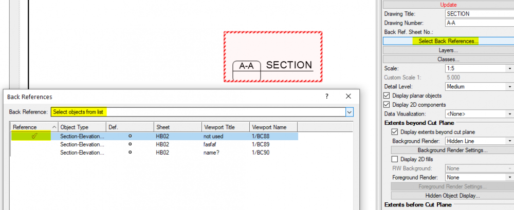
Yes the list will be unpopoulated by default with "None" in the "Back references" drop down. You need to select an option other than none. That would be great Michael. I thought I had updated it a while back when we were posting about this on another string. Maybe that's why it's not working on detail viewports! Cheers
-
Ok, I didn't know the default vp name could update like this. Not sure how useful it is if only the drawing number that updates and only if the sheet number hasn't changed. For software that boasts of 3d bim and auto coorodination etc this is a real failing. Viewport naming is essential for 3d work esp on larger projects and haveing to do it manually is just not really good enough. I recommend using the script posted earlier. It may also work on section viewports but doesn't work on detail viewports.
-
I had a quick look at your file. As mentioned, vp's don't auto update to changes in sheet number or drawing tile or vica versa. If you meant the Drawing Label doesn't update then I don''t seen this behavior in your file. The sheet number in the drawing label doesn't seem to change but as soon as you zoom or pan the label updates. I don't understand this. Your Drawing Label "Accord Primary" doesn't call up the drawing title. Your Labels "Accord w back ref" & "Accord Secondary " updates ok when the vp is selected and the drawing title or number are changed in the OIP. Are you seeing different? See attached screen recording. Yes, vp names and drawing labels are not linked. Can you explain this more? From your PM: "When you go to page 03 having section A-A on it your will notice that the anticipated back reference to page HB01 has not filled in either." You need to select which markers you want as back references. Select the vp and click on "Select back references". Best to choose "select objects from list" then put a check mark next to the marker/s you want to back ref.. If you want to keep your vp names to match the sheet number, drawing number & drawing title then @michaelk has developed a really good script which will name selected viewports. Posted below. Be aware that with v2021 it's probably best to just use this on top/plan viewports. You can see how it works in the screen recording. I use it so much I have put it as a menu command. Procedure ViewportRename; {Badly Scripted by Michael Klaers. Updated Aug 2, 2015} {This script will take all selected viewports and change the name of those viewports to be (Sheet Layer) (Drawing Number) (Drawing Name) This version tries to force the name to appear immeidately in the name field, data tab, OIP when only one VP is selected. Prior to this version the new name appeared immediately in the Nav Palette, but not in the name field.} Var VPDwgTitle,VPName,BText,VPNum : String; h,hh: Handle; ViewportLayer: Handle; ViewportLayerString: String; Procedure RenameVP(h : HANDLE); Begin {*********** BEGIN Procedure ***********} ViewportLayer:= GetLayer(h); ViewportLayerString:= GetLName(ViewportLayer); VPDwgTitle := GetObjectVariableString(h, 1032); VPNum := GetObjectVariableString(h, 1033); ResetObject(h); { Message('Viewport Handle: ',h,chr(13), 'Layer Handle: ',ViewportLayer,chr(13), 'Layer Name: ',ViewportLayerString,chr(13), 'VP Num: ',VPNum,chr(13), 'VP Name: ',VPDwgTitle); } SetName(h, Date(2,2)); SetName(h, CONCAT(ViewportLayerString,' ',VPNum,' ',VPDwgTitle)); SetDSelect(h); {These two commands are just here to force the new name to appear in the } SetSelect(h); {name field immediately. They can be deleted w/o consequence} End; {*********** END Procedure ***********} Begin {*********** Main Program ***********} ForEachObject(RenameVP,(((T=VIEWPORT) & (SEL=TRUE)))); End; Run(ViewportRename); 2021-05-27 13-39-16.mp4
-
If @michaelkis right (which he usually is) then perhaps try a purge on a copy of the file to see if deleting unused symbols will also get rid of the unwanted classes. The purge command gives you a preview of all the unused symbol definitions so that might narrow things down a bit.
-
There must be some symbol definition or plugin or something that uses the unwanted class. Vectorworkaround: add a “zz-“ prefix to the class name. They will drop to the bottom of your class lists. Out of sight, out of mind!
-
Seems odd. Can you post the file to the forum? Happy to have a look.
-
Make sure you have "use automatic drawing configuration" checked in the File>Document Preferences>Display dialogue. Just to clarify, "drawing title" and "viewport name" are two entirely separate things. The drawing label should update automatically to show the drawing title. The drawing label is not connected to the Viewport name which is at the bottom of the OIP window and, unless you use a script is only edited manually. Nothing is new with this. This functionality is just the same as with the previous drawing label.
-
Well done Michael. Spot on. I just discovered that before you posted. I had a few erroneous objects way off the origin. Deleted them and now seems to be ok. Thanks! Not sure how they got there. They were literally miles away... Cheers
-
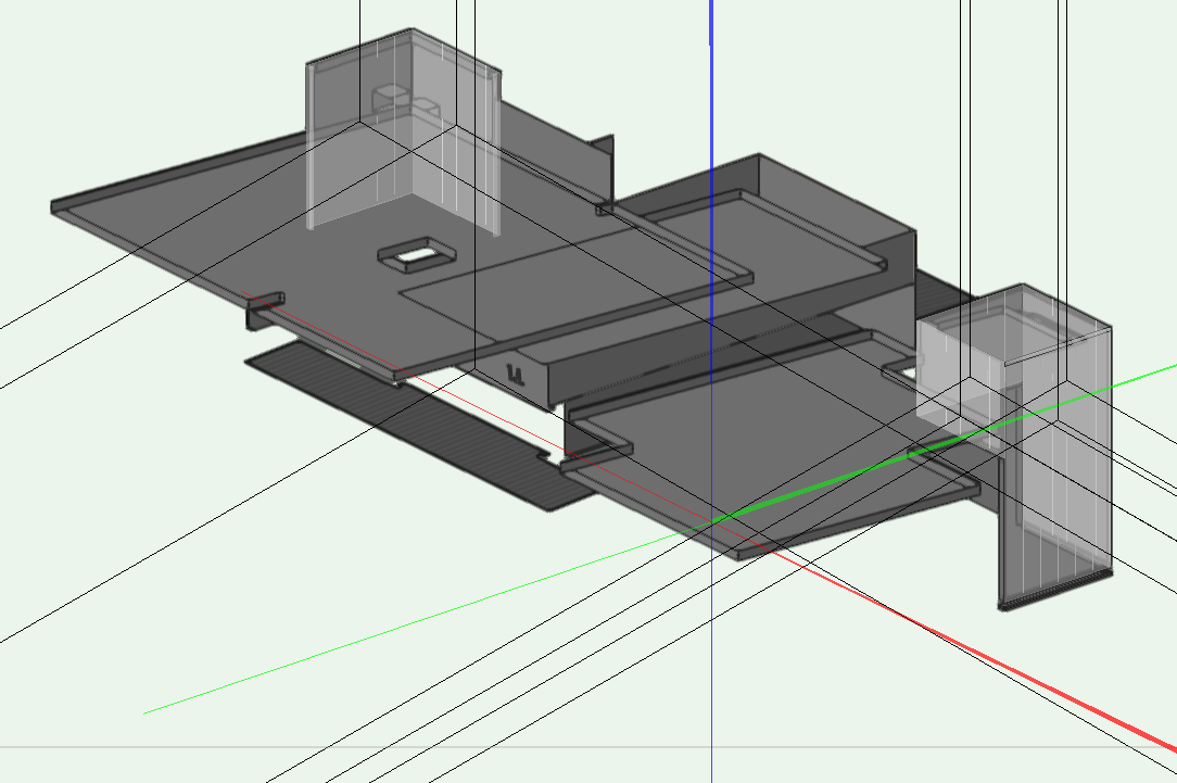
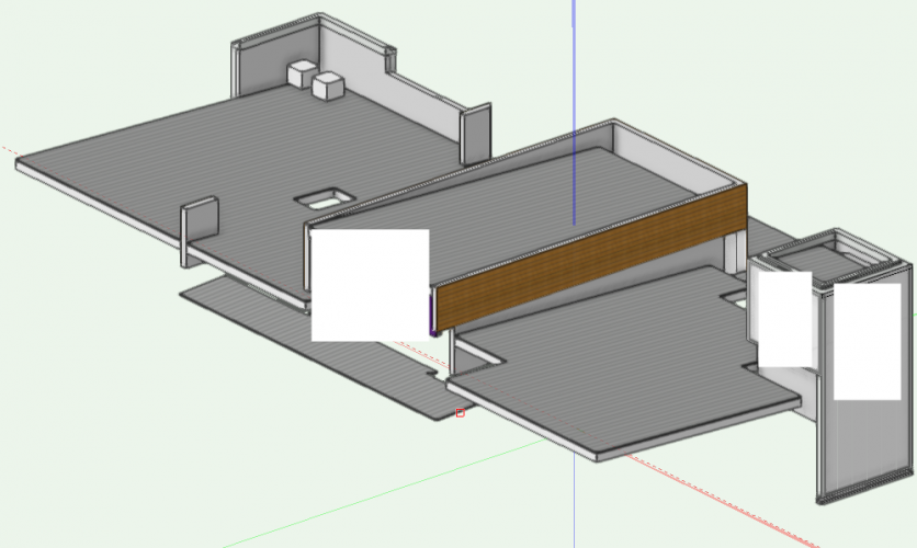
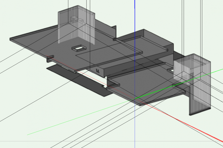
I'm hoping someone can help with this. I can't seem to get OpenGL to work. The textures on a file have gone transparent and locus points have turned "full screen". This is what it should look like (ignore white rectangles): But this is what I'm getting: If I fiddle with the OpenGL render options it might work for a bit briefly on some design layers. Unfortunately I just noticed it and I can't retrieve any backups. This is a vw2021 project. Any suggestions appreciated. Thanks. So far it only seems to be happening on one project
-
How to have symbols use class attributes in top/plan
Boh replied to hollister design Studio's topic in General Discussion
There is no equivalent to the autocad "By layer" & "By Block" attribute controls in vectorworks. I understand this is a wish list item dating back for some time. I haven't found a workaround for giving different attributes to the same symbol using classes though you could try data visualisation to do this. For controlling visibilities of symbol geometry, from experience I generally suggest you avoid putting differently classed geometry within a symbol definition. This means that you may need to have 2 or more classes visible for the symbol to appear correctly. If the symbols are just for your use then you can probably manage it ok but if the symbols are going to be in a library for others to use then unless you have a well understood office class standard then inevitably people are going to get the visibility settings wrong. I have two ways I typically set up symbols: 1. Put symbol geometry on the none class with attributes controlled by object (rather than by class). As the none class is almost always set to visible the visibility of the symbol is only controlled by one class - that being the class in which the symbol instance is placed. 2. Put symbol geometry on different classes with attributes controlled by class (rather than by object). I like to use classes a lot to control the attributes of geometry as it allows attributes to be overridden in different viewports and global control of attributes across a file. Sometimes I will also extend this to use different classes within symbol definitions however to avoid the multiple class visibilities issue I will only do this if the symbol instances are typically placed on the none class (i.e. the inverse of the previous suggestion) and the symbol geometry classes used are always set to visible. I tend to use this approach more in viewport annotations, such as in detail drawings, as the symbol instances can just be placed on the none class. This approach works well across a workgroup if there is an established class standard so everybody know what the classes are for and understands how to set their visibilities. If you are making symbols that others will use and don't have a good class standard understood across the office then best use option 1. -
Hey Elle. If the palettes are on top of each other can you not just move them? Unfortunately the file you posed is the student edition so can't open it.
-
Setting how a drawing centers on the Internal Origin
Boh replied to AmandaM22's question in Troubleshooting
For the top/plan viewports, when you go from sheet layer to design layer via a vp, you can get vw to create a green outline of where the crop is on the DL. If you do this for each vp before moving everything it makes it easier to realign your vp crops back to where they were. All your vp annotations will need to be moved vp by vp unfortunately For section vps, make sure there is a section line for each section vp on a DL. If the a section line is moved with the model then it’s vp should still be showing the same section after the move. -
There is also Vectoworks University and also Ozcad who have aome good free instruction vids on their range of third party plugins included in the Australasia release such as the WinDoor tool.
-
Nice job! I did an old villa a while back and after 2 site measures couldn’t work out why the upstairs walls didn’t line up with downstairs - some walls were 100mm or so out of alignment. Finally figured out that the original high stud walls weren’t vertical but more recent reno walls were!
-
Stop it with the implied bezier curves with the poly line tool!
Boh replied to Ride's question in Troubleshooting
I only just cottoned on to this feature recenetly and now that I know why and how it works I really like it! It makes drawing polylines (with curves) so much smoother once you get used to it. -
Not sure if there are any settings in the marker tool that will do this for you. A work around might be to edit the interior elevation marker style so that it fits in the room.
-
Additional snap tips: You can create some custom tool scripts from the custom tool dialogue. I have one to set snap settings for detailing and another to set them back to my preferred defaults. One click trick! Also if you hold the ctrl+shift while pressing the arrow key the selected items will nudge to whatever your current snap distance is. This is set in the preferences under nudge settings. Using this you can rapidly nudge stuff around your page set distances without having to type in any measurements.
-
What @zoomersaid. Another tip is to get in the habit of using the shift key to help constrain line work to vert horiz and snap angles. If you have the floating coordinates set to be visible then with the higher precision tolerance you can see if line work is slightly off the correct angle as you draw. Also if your work is mostly rectalinear then activating the snap grid set to say 5mm helps to keep everything tight. For detail drawing I set the snap grid to 1mm.
-
Setting up Office Standard for managing symbols with record data info.
Boh replied to Boh's topic in General Discussion
Thanks @jeff prince and @markdd. My approach has to be all carrot! As we haven’t been using record data and data base worksheets for scheduling in the office much no one has really got much experience on how to set it up. It would be good to get the bones of a basic workflow together which I can then take to my team as a starting point. Keeping things simple I think is a gd idea. If anyone has any other clues to common pitfalls they have experienced working with records and database worksheets across an office workgroup that would would be amazing. Thanks -
Setting up Office Standard for managing symbols with record data info.
Boh replied to Boh's topic in General Discussion
Thanks @markdd. Yes I use the attach record command which I think is going to shortly get a lot more use from me. If you read on in the thread of posts you’ll see I have taken advice from others about not using VW to manage data so while I plan to attach a custom record to symbols I won’t be doing a lot more individual editing of that data for each symbol. I can see now that it is not really worth the time spent. Yes we already have a fairly comprehensive library placed in a workgroup folder as well as some pretty good project templates. This post was more about how to set up a system for presenting data attached to symbols in a file. Essentially finding the *best* way of combining the use of libraries, symbols, record formats, data tags and worksheets. I take your point though about keeping templates clean. I take a slightly different approach and tend to include some default resources that I know are used on almost every project. We tend to recreate the templates from scratch each time we do a version upgrade (every other version) so we take that opportunity to clear out out of date stuff. What is your advice with regard to setting up an office standard for record info/data. Cheers -
Setting up Office Standard for managing symbols with record data info.
Boh replied to Boh's topic in General Discussion
Thanks @halfcoupler & @jeff prince Yeah so clear messaging there: simpler is better!! @jeff prince I appreciate the “lone wolf” comment as I’ve been guilty of that in the past. Yeah I don’t want to spend a lot of time developing an amazing complicated system that only I will end up using. That said getting staff to appreciate the benefits of a smarter way of doing things is no easy task. No matter how significant or obvious the benefits of a different approach are sometimes people just resist change. We do need to get a more coordinated approach to how we specify this stuff however. So I’m hopeful that, without spending too much time, and with help and advice from experienced users like yourself and @halfcoupler on this forum I can set up the bones of a basic system that will have the essentials in place and be accessible enough for others to appreciate its advantages and how it can work for them. If I can do that I will at least get the “buy-in” of the more progressive staff. So to simplify things down then this is what I am now thinking: Just have one main record format attached to almost all library fittings symbol definitions. (This would include plumbing fittings, equipment, furniture and even light fittings). The record would have just two fields: 1. “ID” (with “[ID]” as the record field default) and, 2. “Description” (with a blank as the record field default). To avoid the data management nightmare, library symbol definitions would generally just be left with the record format defaults. Specific data would be added to the symbol once it’s brought into a project file where it can be tailored to suit the project requirements. Custom data tags and preformatted database worksheets would be added to the project templates files. The custom data tags would link to objects with the record format. The tags would just display the symbol’s “ID” field. (Different versions of this tag could be used depending on if the symbol is a plumbing fitting, equipment or furniture etc). The worksheets would just have the two columns to report on I.e. the ID and description record formats. Worksheets could have criteria so they only call up records present in a sheet layer and/or alternatively, using classes, they could just call up plumbing, electrical or furniture fittings. How does that sound? Do you think this is still too complicated and could be simplified further? Please keep the advice rolling in! 🙂 @halfcoupler I really like the idea of managing the data outside of vw. Can I ask if you work in a collaborative office scenario with this system or are you a sole practitioner? Also do you issue your indexed external spreadsheet with the project drawing set or do import the spreadsheet into vw or copy / paste the info from the external spreadsheet into a worksheet in your vw file? Also how do you do your indexing? Do you use a script to index your symbols or do you do this manually? Are the index numbers used as identifiers on your drawings sim to my ID field? Or are they used purely for internal management of symbols? Please if others have advice please chime in! Thsnks -
Hi, I’m looking for any advice and tips people are willing to throw my way. We are a smallish architect practice and Im hoping to streamline our scheduling of things like plumbing fittings, equipment/appliances, lighting, furniture etc. We don’t have a standard way of doing this, and what we do basically involves a lot of callouts and notes that have to be reinvented for each project. We have a good library of standard 2d and 3D symbols for all this stuff. What we don’t have are custom records or data attached to most of it. Nether do we have a decent collection of data tags, or custom worksheets for reporting on this stuff. So I’m now looking to add custom record fields with symbol specific data to the symbols in our library and from this the plan is to be able to drag a symbol into a project, slap a data tag onto it and have some nicely set up worksheets on our drawings available to display the preformatted symbol data. We can then add and edit the data as required for the project from within the worksheet to pretty quickly spit out plumbing, equipment, lighting and furniture schedules on drawings. This is something I have wanted to do for some time but it is quite a leap from how our office has done things in the past so I’ve always thought if I’m going to do it I need to do it really well. I know it is the way forward and wil be a massive time saver, but a half baked system won’t get the uptake I need for it to become established in our office. I’m now taking the dive and would dearly appreciate the advice of people who perhaps have driven this road before. So I know the basics of how all this works and yesterday I thought I’d start out with plumbing fittings. So I spent some time first creating a custom record format for plumbing sanitary fixtures. I thought through what fields I would need and how setting up the correct fields would impact on how the info would be pushed through onto worksheets on drawings. I set up an “ID” field as well as “Fixture Type”, “Style”, “Location”, “Description” fields. So for example a wash hand basin might be: ID: WHB Type: Wash hand basin Style: Wall mounted Location: [project input] Description: Caroma Caravelle 500 Wall basin with methven blah blah mixer, 40mm outlet etc etc. I thought while I’m at it I might as well add some more record fields that may be useful so I stuck in “Manufacturer”, “Model”, “Model No.”, “Finish”, “Size” and “Price”. Though most of this could be covered in the “Description “ field. I then made a Data tag that would attach to objects containing the Plumbing Fixture record. The data tag would display the ID field and help anyone reading the drawing see which schedule item related to which item(s) on the drawing. I then started attaching the record to the many plumbing fitting symbol definitions in our library and one by one editing the field data to suit each symbol. This was very tedious but I kept reminding myself that it would save a lot of time in the long run. This isn’t the first time I have done this, I have managed to do this sort of thing on various specific projects but it is the first time I have set it up as part of a library with the intention for it to be an office standard. So developing a pragmatic, flexible, intuitive system that makes sense and is easily applicable to the various types of projects we do and that everyone in the office can understand and benefit from is the tricky bit! Are there people out there who have “been there done that” before and can offer some great tips? Questions: Do my custom records need anything else? I must have edited and re-edited them a dozen times trying to figure out if they covered everything off. Or should I trim them right back to keep them really simple? Any suggestions appreciated. It would be good to know if there is a quicker way to add data to symbol definitions. That is by far the most time consuming aspect of this. I know there is a command to add a record to all symbols in a selected RM folder. But subsequently editing the data from the record field defaults to something specific about the symbol it is attached to is painfully slow. Can the Data Manager be used for this? I had a look at it and found it more confusing than anything else. Do I need different records for plumbing fixtures, equipment and furniture? They would all have the same type of “ID”, “Type”, “Style”, “Location” and description fields so why not just have one record to cover them all? If they all used the same record I could more easily combine them all into one worksheet which would be useful and they could be all covered off with one type of data tag. I could also use classes to filter stuff in or out of the worksheet schedules. For worksheets is it a good idea to have individual worksheets for each sheet of a project file calling up the data from all the symbol data present just for the viewports present on each sheet? Then also have an “editor” worksheet so that data from all plumbing fixture symbols (or equipment symbols or whatever) in the file could be managed in one place? Or is there a better way this is just creating unnecessary work? Any tips on setting up useful data tags? Could some generous soul please share their own super flash custom data tags? Mine look pretty crap... Well done for making it all the way down here and thanks for even reading all this! Hopefully you are inspired to share you IP!! Cheers.
-
You can change the vw icon with custom colours. See this post: