


cberg
-
Posts
912 -
Joined
-
Last visited
Everything posted by cberg
-
With every new version, I keep hoping for the ability to use data tags with symbols.
-
Vw2025 Section Viewport Object Visibility - Troubleshooting
cberg replied to cberg's question in Troubleshooting
And then there are the partially hidden object artifacts.... Sigh. The objects that won't go away are symbols that appear to be cut by the section viewport if that helps troubleshoot the issue. Screen Recording 2025-03-20 at 8.14.07 AM.mov -
Vw2025 Section Viewport Object Visibility - Troubleshooting
cberg replied to cberg's question in Troubleshooting
There appears to be a bug associated with object-level visibility. After setting up a file with three sheets of viewports (35+), each with object-level visibility set during viewport creation, the file decided to show objects that were set to be invisible in a half dozen viewports (just before the project was set to print). Zombie invisible object keep reappearing. This type of software glitch is very frustrating and can result in significant quality control issues with Construction Documents / Production Drawings. -
It would be good to be able to set the defaults for the 3d Mass Property (Weight) Calculations. I had to find weights of a bunch of steel pieces and the dialogue box kept reverting to defaults that I did not set.
-
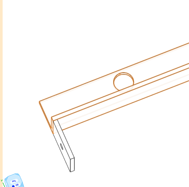
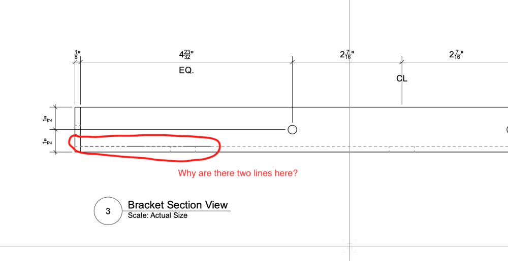
Like Hidden Line Render Mode, the Dashed Hidden Line render style is replete with glitches. The attached screenshots are taken from a model which consists of 3 solid objects. As files go, the model is about as basic as one can get. However, additional linework appears in the Dashed Hidden Line rendering. I have checked the solids, and there is no stray linework embedded in the 3d geometry. However the resulting viewport rendering is not clean. Something this basic, shouldn't be this difficult!
- 1 reply
-
- 1
-

-
The Attributes palette takes up a lot of VW real estate, relative to its functionality. The big bars of color and transparency waste tons of space, and do not look all that attractive either. We need a version that can be minimized for use on laptops and smaller resolution screens.


-
It's very frustrating to encounter inaccuracies in VW Hidden Line Renderings. Curved steel sections, in particular seem to prove challenging. The first image shows the assembly rendered in shaded render. The second image shows the bottom edge missing. It is one CGS solid. Adjusting the smoothing angle doesn't seem to help. Why is something so basic so difficult to do well?


-
Vw2025 Section Viewport Object Visibility - Troubleshooting
cberg replied to cberg's question in Troubleshooting
Thank you for alerting me to that dialogue box. It was unchecked, and grayed out since I don't usually use the Edit command. As I explore the file, however, something still seems wonky. In my main work file I wound up deleting Section Viewport 2 (a-1 Angle Section) and recreating it from the design layer viewport. That action reset the visibilities of sections 5 and 6 which are now behaving as I would expect. Sharing a stripped down version of that file to see if you see something that I do not. Object Visibility Test File.vwx -
Vw2025 Section Viewport Object Visibility - Troubleshooting
cberg posted a question in Troubleshooting
Can anybody help troubleshoot how to adjust object level visibility in a section viewport? Yesterday, I set up a sheet of viewports with the desired object visibility. I closed and saved the files. This morning, all the hidden objects reappeared. In the screen recording, I try resetting the Object Visibility in the first viewport and “re-hiding” the objects. Editing the model via “Section in Place” does not change object visibility in the viewport. In the second viewport, I edit ”Section in Place.” The hidden object is invisible in model space but visible in the viewport. Am I missing something? Or is this a bug that needs to be worked out? I thought I read somewhere that Section Viewport object-level visibility can be adjusted via “Edit Section In Place”. VW 2025 Object Visibility - Section Viewport.mov -
Why don't data tags work in a perspective viewport? This functionality would be very useful in creating assembly diagrams... It appears that the geometry that VW depicts in the perspective viewport is very different than the geometry that the Data Tags highlight...

-
Use both. Point cloud for overall spatial relationships and details you would miss if documenting by hand. Laser measure areas that are critically important. Use the laser to check overall measurements and calibrate the scans. Not every project requires 100 percent accuracy. I always refer to this when thinking about point clouds. Useful even if you do not use Matterport. https://support.matterport.com/s/article/How-accurate-are-dimensions-in-Matterport-Spaces?language=en_US
-
I have had a similar problem with a point cloud using single window pane. Try temporarily changing the point cloud color mode from color to grayscale and then switching back to color. This resets the 3d render info and allows the point cloud to show up in a shaded view. While I haven't had time to submit I think the software has a bug. https://app-help.vectorworks.net/2025/eng/VW2025_Guide/Objects_edit2/Coloring_point_cloud_objects.htm#h
-
@mikeakar You may want to check the scale of your bricks. To my eye, they seem a little large. Also, the black of the table legs and posts in the center feels better than the black of the stairs, light fixture, and table along the window. Is it the same material? When the black gets too black (without reflection), it makes that area look fake and flat. Also, I would like to see if you can adjust the wood textures (per face) so that the grain aligns, especially at the trusses. There is something a little quirky with all the wood at the ceiling. Overall, you've done a much better job in VW than I could ever do!
-
Or you can export the model into Twinmotion (free) and get output much more to your liking in about one-tenth the amount of time. With VW, the effort-to-reward ratio is not especially efficient. I gave up when I tried to import textures into VW and realized that the rendering engine doesn't support the texture categories and settings associated with many other render programs. Sorry to sound contrarian, and hopefully this doesn't come off as criticism.
-
Structural Member usability improvements
cberg replied to LarryO's question in Wishlist - Feature and Content Requests
For that reason, I still use framing members. -
Part of the problem is that your Roof Face uses a rectangle as the base geometry. There is a VW2024 Bug in which the Reshape tool cannot change floor and roof face objects that use rectangles to create them. You can use the Reshape tool if you convert the rectangle to a polygon. Alternately, reshape the roof by double-clicking into the roof face. This bug was submitted in VW2024 SP-0 and wasn't fixed until VW2025. However, there are other ongoing issues with roof faces which may or may not be related.
-
I had that problem in VW 2025. To fix it, I created a new file and imported the roof layer, including layer objects that reset the roofs. If that works, copy the roof faces back into the main file after creating a new layer. Delete the original layer with the corrupted roof faces.

-
The challenge for architects using Connect CAD may be similar to using InteriorCAD's cabinetry suite rather than the updated VW2024 Cabinet Tool. The former is for highly technical production, and the latter is intended to show design intent and maybe a little bit more. Only a few very gifted architects can engineer their own electrical systems. Most probably have a basic concept of how devices and lights should (generally) be circuited. When the project gets too large, we would likely get a second professional opinion and some design assistance. The VW MEP Toolset has been forgotten (abandoned?) since around the year 2000. At some point, these tools need to be modernized like the rest of the program. This is a good opportunity to ask what tools would help the current (and future) user base.
-
VW2025 - Roof Faces won't select in 2d Plan or show up in 3d
cberg replied to cberg's topic in General Discussion
The file was created in VW2025, and I was in SP-2.0 when the error occured. I updated to SP2.1, which did not fix the problem. -
Rather retool another product which is not intended for architectural design, why not acquire and localize the Benelux tool which does what users in this thread are requesting? Or at least make it available for purchase as some sort of partner product? It's frustrating that a solution exists but it is not available to the majority of VW users.
-
Vectorworks 2025 Update 2.1 - Installer Problem
cberg replied to cberg's topic in General Discussion
@Tim Ardoin - Sent. @Pat Stanford Your suggestion worked, thank you. -
When I attempt to update to VW 2025 - SP2.1, I get an error message stating that I must close Vectorworks 2025 first. Vectorworks 2025, however is not open—any ideas as to how to fix it? Restarting did not help.
-
I was working on a file, adjusting the walls next to this roof; without warning, two adjacent roof faces suddenly disappeared. I thought it may have had to do with Show and Hide objects. I can't seem to force select. However, when I copy the layer objects into a new file, they appear and can be selected. Any ideas as to what I may have done to create this problem and what I might do to fix? Existing Conditions Model - Test.vwx

-
You can make a curved wall and set the fill to use a batt insulation tile. If you want everything to look 2d, set the wall height to zero. This will only work with arc curves. curved batt insulation.vwx
-
It sounds like I should just import a combination of the base color and the ambient occlusion to get a decent Shaded Render Image, and not try to expect too much else. If and when I bring the material into another render program, I can add the bump, reflections, later.


