markdd
-
Posts
3,412 -
Joined
-
Last visited
Content Type
Profiles
Forums
Events
Articles
Marionette
Store
Everything posted by markdd
-
There are two places this content can go. The Application folder or the User folder. Most likely it is in the user folder, but it will be one of those. To locate the User folder, go to the Vectorworks preferences dialog and in the user folders section select reveal in finder. I’m fairly certain this is where the content goes. Personally I never download any of the content and just use it on demand from the cloud.
-
Make sure that in Vectorworks preferences you have “enable premium libraries” checked.
-
Picking a hidden surface or face using Windows
markdd replied to markdd's topic in General Discussion
@Pat StanfordAh, it's the Alt Key! Thanks. -
Hi When working with the 3D Modelling toolset, selecting a hidden edge or face is possible using the option key on a Mac. Can anybody tell me what the equivalent is on a PC? I can't find any documentation for this anywhere. Many thanks Mark
-
hiding stuff in viewport (not by class/layer)
markdd replied to Tomas Lohin's topic in Entertainment
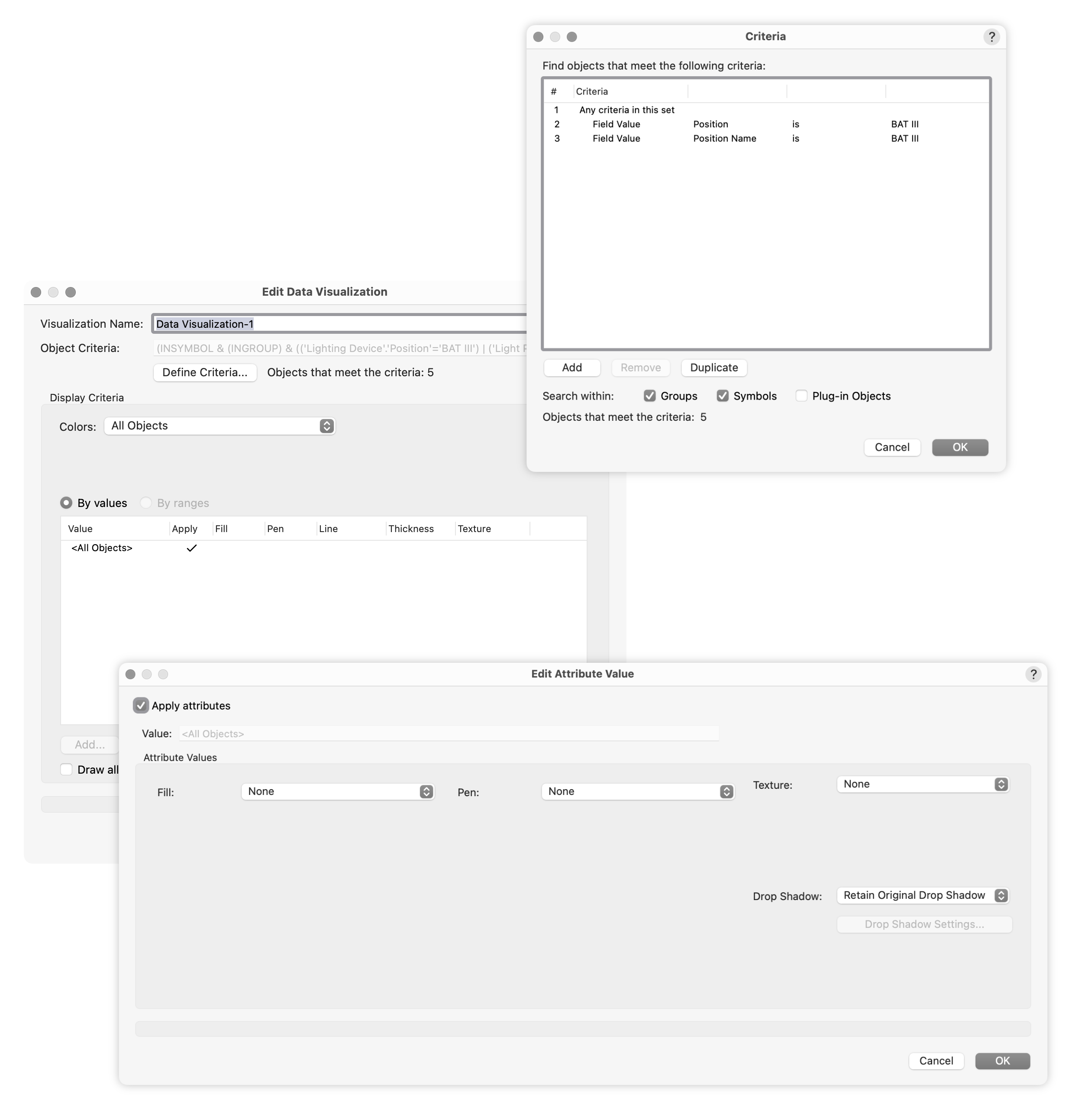
The Criteria were the Field value of the Hanging Position (Position name) and the Lighting Devices (Position). The criteria could also read CONTAINS BAT and the same result will apply.
-
hiding stuff in viewport (not by class/layer)
markdd replied to Tomas Lohin's topic in Entertainment
I'm afraid I don't really know what you mean. Can you show an example of what you want to show/hide or better still share the file? -
hiding stuff in viewport (not by class/layer)
markdd replied to Tomas Lohin's topic in Entertainment
Great. If you attach a record to the lighting bar geometry, or better still if the geometry is a symbol, you can then choose to show or hide the geometry based on the Record it contains. -
hiding stuff in viewport (not by class/layer)
markdd replied to Tomas Lohin's topic in Entertainment
It depends exactly what you are trying to do, but Data visualisation would probably be the way to do it. -
I think in general with referencing you need to be able to keep track of where everything is. Google Drive and Dropbox work well with referencing as long as you keep the files locally and don't allow the cloud drive app to make them "cloud only" after a period of time without use. I know Dropbox does that which has caused problems in the past although not with Vectorworks. So no, as long as you know where they are, and use relative referencing rather than absolute, you should be OK. I don't use templates to hold anything other than the most rudimentary of settings as for me, they cause more problems than they solve!
-
Of course why not. Make the master file with all your symbols Probably best to add it to its own folder Make 3 other clean files, one for each venue Put them in the folder with the Master File Import the Symbols you want from the Master file by right-clicking on them in the resource manager from the master file and selecting Reference. A reference between the two files will be made and the referenced symbol will be in italics to let you know that it is referenced. You can edit the symbol from any document and the changes will be pushed to all the other documents, or you can break the reference (Right-click on the Symbol listing in the resource manager) and edit it for just one venue.
-
Check whether the dimensions class is either turned on or has pen attributes set up correctly.
-
Try turning on ambient occlusion and indirect lighting to interior.
-
Yes, that looks about right.
-
You also need to turn off ambient light in the Lighting Settings dialog.
-
All the lights need to be directional. It looks to me as though you have a point light in there as well.
-
You only need 1 symbol as there is no light fall-off and the symbol can be positioned anywhere on the design layer.
-
The directional lights can be placed anywhere and there is absolutely no fall off. Point lights have intensity falloff even when set to none. Most importantly though, they are directional, so the position of the light will make a big difference. It's hard to explain without an example.... Point Light Directional
-
I have a symbol in my library that I add for just this scenario. It consists of 6 light objects set to directional. 4 of the lights at point at 90 degrees to each other and the last 2 point directly up/down. Set them to not cast shadows. You can adjust the intensity of the symbol and I find 50% normally does the trick. this is as shadowless and even as I can get and is good if you want to have completely even illumination.
-
Or, to retain the settings to be used on any truss length, you can convert it to a Plug-in (Red Symbol). To do that make sure that Convert to Plug-in Object is checked.
-
The Lighting Pipe Tool in the Spotlight workspace has a multi-level mode bar depending on the mode the tool is using so I think this is something that could easily be possible. ....
-
If you are in an Isometric view for instance, the Move 3D Command will move the object along either axis according to the Axes of the Active Layer Plane regardless of your view. If you were to apply the same values using the Move 2D Command, then the object will move the same distance, but relative to the view you have of them on the screen in front of you. It's just a different way of thinking. If you were to combine the commands, then you would need 5 fields divided into Screen (X and Y) and World (X,Y,Z).
-
Yes, if you are working on an object and you are looking from beneath the Working plane, then the only reliable way to move something Left/Right, or Up/Down along the X/Y axes is to use the Move 2D command.
-
If you are working on a Working Plane, then things can get a bit confusing, especially if all you want to do is move an object up the screen by a certain amount. Often I have changed the Z value in the Move 3D command and the object has moved in the opposite direction to what I was expecting. The Move 2D command seems to be foolproof in that regard, and will always move the object relative to the view of the object on the screen.
-
What's good about the Move 2D command is that it works in the primary Orthographic Views (Top, Bottom, left, Right, Front, and Back). When viewing an object using one of these Views, the 2D or 3D object you selected will move relative to the view on the screen. This can be more intuitive, especially when using Working Planes etc. The Move 3D command uses absolute 3D values which aren't always as helpful. That's my reasoning for keeping them both....
-
Using Subtract or Section on Hollow Object
markdd replied to stayathomedad's topic in Solids Modeling
Actually, you can make a multiple surface selection with the Shell Solid tool which would remove the need to cut the ends off.