


Conrad Preen
-
Posts
1,023 -
Joined
-
Last visited
Content Type
Profiles
Forums
Events
Articles
Marionette
Store
Everything posted by Conrad Preen
-
We got the message!
-
@spettitt thank you very much for the feedback. These are all basically content wish-items. The extent to which they can be addressed depends on available resources. I will log them but at the moment I can't make any promises. Of course you can develop this for your own use including adding extra classes. If you create a well-structured library I could certainly propose the idea of Vectorworks buying in this kind of content from power users. Best Conrad
-
@wscooper I think we need to moderate our expectations. Cable cross-section is calculated as a rough guide to help estimate the requirements for cable containment (trays, ducts etc.). The cross-section is calculated as diameter x diameter - nothing too clever. And that needs to be de-rated to take account of cables passing over each other as they turn corners. The realities of installation can make a huge difference to how much space is taken up. Same is true of cable lengths. An installer whose brain isn't functioning can destroy any estimates simply by dressing the cables in a weird way. Then add to that the fact that cables come on spools of a give length so again your installers can easily cost you several extra spools. And it might not even be their fault - it could just be logistics. Of course if there are ways to improve this in a manner that is practically useful I'm all for it. But let's not chase the dream of a perfect computer model only to have it trashed by the realities of life on site. Conrad
-
There are two cases really: when you don't know the equipment to be placed but you have to design the cable paths when you already know the equipment. I think for the latter case it would be quite nice for an equipment item to be able to function as a drop point so as to save having to place both. But we (ConnectCAD team) need to talk this one thru to make sure there aren't any rock in the road. Conrad
-
Hi @wscooper this is a way for you to indicate that a socket is the termination or source for multiple circuits. It isn't anything particularly clever. When you set # Circuits to a value > 1 that number will be displayed next to the socket. And it will appear in Circuit reports. ConnectCAD doesn't do any checking to see if the values make sense - that's is left to you the designer. Essentially it's just a visual aid. Conrad
- 1 reply
-
- 2
-

-
@wscooper Hey, help me out with those acronyms! What's a GA?
-
I fully agree! Interesting suggestions too. There maybe a way forward like that but I will need to work through all the cases. I'll be back! C
-
@wscooper Hi Will, This particular thing goes both ways. The line between equipment and drop points is blurred. There are times when you'd like to take a cable path to a piece of equipment and there are times as you say when the drop point is in effect the end point of the cable. These things keep me awake at night! The reason why we have drop points at all is workflow. Quite often you have to make decisions about the physical routing of cables long before you have any idea of what will be connected to them. Say you are called in as an AV consultant on a new building. You'll receive a bunch of architectural plans and the first thing you'll have to do is mark where cabling will go to - i.e. drop points. You will have to show what cabling (at least a guess) goes between them because some routes will become inaccessible during the building process. You can't specify equipment in detail before building works are complete because it will all be out of date by the time you install it. But there are other situations I agree. The way we do it now - attaching equipment to drop points doesn't imply an extra length. The equipment simply uses the drop to access the path network. You could style a drop point to look like a patch panel, but then it wouldn't be in your equipment report. But you could customise the criteria of the report to include drop points. So maybe that's a way forward? I like that fact that you've raised this point. Let's keep the discussion going and who knows maybe an even better solution will emerge? Conrad
-
@Zrasap Hello, could you post a picture of the situation you are trying to model. Just to make sure I understand the question. Conrad
-
@spettitt I certainly don't want to take away the ability to add extra signal, connector and cable types. We could never keep up anyway. No worries. Regarding the taxonomy of device definitions: we have the top-level categories based on the primary signal (video, audio, control etc.) and the functional type of the device (mixer, projector, camera, speaker etc.). I think it is rare that we'll need extra top level categories, but for sure the functional types have no covered every case by far (and some could be consolidated). The aim is to make it a bit easier to locate what you are looking for in the database. It will never be perfect. As you say the industry is vast and fast-moving. An interesting thing to consider would be to separate signal type and protocol. These days a huge number of devices communicate over Ethernet but use different protocols. Maybe its time to add Protocol as a separate socket property? What do you think? Conrad
-
@alexmootv @spettitt If you have some extra categories to suggest this would be a very good time to tell and I can see if they could be added to our taxonomy. Conrad
-
Well this is one those places where there are two kinds of people in the world. Those who want thousands of ready-made devices, and those who want to do their own thing. Personally, I'm with you guys. I wouldn't trust a library device because I know what can go wrong. But we are in the minority which means that as far as libraries are concerned ConnectCAD has to "tick the box". Another issue to think about is collaboration. Increasingly we are seeing projects being handled by design teams drawn together from different countries and companies. If they aren't all singing from the same song-sheet things can quickly get into a real mess. All this is driving us in the direction of keeping categories and types under Vectorworks control rather than users inventing their own. Regardless of my own opinion as a designer, I am definitely in favor of commercial success otherwise there won't be a ConnectCAD. I also have to bear in mind that the people who are happy with the status quo hardly ever post on the forum to tell us how happy they are. This is an unfortunate fact of human nature. I'm not promising anything but we do try to please all the people all of the time! We will bear you comments in mind moving forward. Conrad
-
@everyone if you are reporting a problem it's a great idea to share the file immediately so we can get to work. If you have concerns and don't want to share publicly just PM the file or a link to it to me or Niko. Conrad
-
Multiple signals/circuits in one socket
Conrad Preen replied to Edward Carlson's topic in ConnectCAD
Hi @Edward Carlson In the Circuit Object Info Palette you can set the cable number to be displayed at only one end of the circuit. When I used to design these before we had all these nice new facilities I used to give those intercom/tally connectors the same number for all since in any case it would be a special cable that got made up on site. By the way this would be a very cool use for a custom Adapter object if you are creating a breakout cable DB25 -> XLR, RJ45 or whatever. It's quite a neat way to do it installation-wise because you can do the soldering on the bench instead of behind the rack. Best Conrad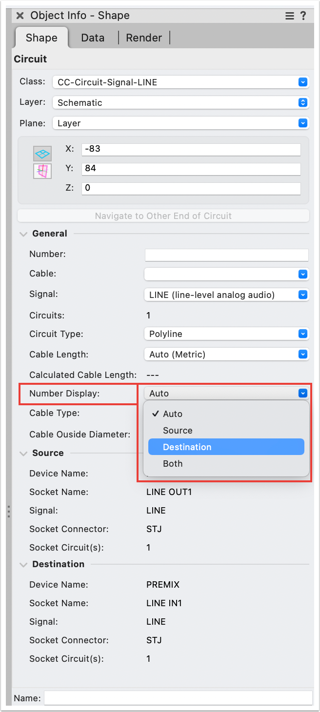
-
Rack Depth vs Usable Rack Depth (Rail to Rail Depth)
Conrad Preen replied to alexmootv's topic in ConnectCAD
We already have variable mounting depth that will be carried forward. Thanks for all the feedback! Conrad -
Rack Depth vs Usable Rack Depth (Rail to Rail Depth)
Conrad Preen replied to alexmootv's topic in ConnectCAD
Thanks @alexmootv, this is a timely comment! We are working on improving the modelling of racks as we speak. I will definitely bear this in mind. Conrad -
Just another thing. Perhaps you are missing the distinction between symbols and plug-in objects? the Equipment Item is a plug-in object whose drawing is driven by its parameters. A symbol is just a passive object that draws a predefined set of objects stored in its symbol definition. At the moment an Equipment Item whose name begins CTP_ draws in front view only. The idea being that you can get the connectors from the schematic and lay them out physically. But as you say that doesn't translate to 3D yet... C
-
Hi Simon, I would be the first to agree that this workflow has some weaknesses. In fact it's that time of year when people on the forum start asking for the features that I'm already planning. But I also have some suggestions for now. Because in most situations the panel design is not a one-off, it can be more helpful to have detailed front views of the panel as a separate visualisation of each panel type and create suitable drop point styles based on those symbols to show where each individual panel is located. That way you are integrated into cable path planning. In the end when it comes to 3D modelling of complex boxes Vectorworks has all the tools you need. The nice-to-have part is to relate the connectors in your 3D model to sockets on your schematic. And yes there is room for improvement. Thanks for the feedback. Conrad
-
@Pat Stanford 2014 !!! wow that's going back some... I haven't done much Vectorscript for several years now as I and now the team have moved everything to SDK. Once you stop using Vectorscript it feels so good you don't want to go back! But let me try... First off, any function beginning ResList_ arrived after my transition to SDK. It seems to be something to do with resource popup controls but I have never used this. I have certainly used ImportResToCurFileN in the past and it works. I notice that the callback is wrongly declared as a procedure FUNCTION ImportResToCurFileN( listID :LONGINT; index :LONGINT; callback :PROCEDURE) : HANDLE; it is a function that should return the values 0, 1, or 2 depending on how you want the conflict to be handled. You need to have defined the function in your code before you use ImportResToCurFileN and make sure it is in scope. The sequence is important. You need to build the reslist, then get the size of it so you can step thru it. If you want to delete stuff then you have to step thru using DOWNTO because you will run off the end of the list and crash. These are the things you have to keep in mind. It certainly did work but it does look like there may be a bug. Do you want to file one Pat? @Thomas W When I was a 3rd party dev I also found the lack of documentation frustrating. At moment no-one is tasked with looking after this and whatever we are able to contribute eats into our spare time. What I found very useful was to download the C++ SDK and burrow around in there. Even if you want to stay with script it's useful to develop the ability to read C++. You get a much better idea of what's going on under the hood. Eventually of course you get sucked in and realise that it's not so difficult to develop in C++ because the tools are way better. That moment when your first SDK plug-in compiles and runs is nerdy thrill second to none! Best regards and wishes for the New Year Conrad
-
Hi @Callum Walker In ConnectCAD multiple devices with the same name refer to the same physical bit of equipment. This allows you to split your project across different layers and separate signals e.g. video, network, audio etc. Just use the same device name and ConnectCAD "knows" what you are talking about. The Check Drawing command helps make sure you don't have the same socket appearing in two instances with the same device name 🙂. Best wishes for the New Year Conrad
-
Hi @Sarajs I'm pretty sure I know why this is happening. I can reproduce the problem as you describe it. We will get this fixed as soon as possible. If you get a moment to send me the file I'd still like to see it just in case there's something else I didn't spot. Thanks for reaching out and letting us know. Best regards Conrad
-
Hi @Sarajs The reason I’m asking to check the file is that we improved the Connect tool to allow you to draw circuits either way. Meaning OUT to IN or IN to OUT. There was a case concerning the sockets in term panels and connector panels that didn’t work but we already fixed in the next service pack. But I want to make sure you haven’t discovered something new. Conrad
-
@Sarajs Could you PM me or post here the Vectorworks doc that is causing the issue? I will take a look at it. Thanks Conrad
-
Thanks for the input @Jeff.Sullivan . We'll certainly consider this as an idea. I don't see WireCAD as an example to follow frankly. Originally the device database was a community-sourced online system much like theirs but we found that it needed a lot of curation to be in any way useful. We'll give it some thought. Bear in mind that we also have to serve those people who want a more centrally administered system. Conrad
-
@Jeff.Sullivan @Pat Stanford That is exactly the case. In a workgroup scenario you would have a CAD manager updating the shared database. The CAD manager's user folder database becomes the model for the workgroup database. He or she adds any new devices by selecting them on a drawing and clicking the Save to Database OIP button. Then the manager can copy the database to the workgroup folder location overwriting the old one. But for freely sharing devices among a design team symbols are the way to go. As Pat describes above. If you create a device using the Device Builder it is automatically saved as a symbol in your current document and you can export it to a shared location using the Resource Manager. This keeps administration to a minimum. If you update the device on the drawing you can click the Save as Symbol button in the Device OIP and update the symbol definition or add a variant with a different name. Hope this helps. Conrad
