


Jeff Prince
-
Posts
2,947 -
Joined
Content Type
Profiles
Forums
Events
Articles
Marionette
Store
Posts posted by Jeff Prince
-
-
17 minutes ago, nicovlogg said:
Is there a reason why I can't get it to work that way or a specific reason why that process is suggested by them as being superior?
You can't get it to work because your existing contours aren't at the correct elevation and you didn't have a grade limit modifier....It really has nothing to do with the method used to add the proposed contours. I don't recall hearing anyone at Vectorworks claiming anything is superior, they seems to be a bit agnostic on methodology. Can you point out where you heard that?
I've been beating the drum for years that people should use points instead of contours. Why, because contours are imaginary and points are real. You can make your own imaginary contours from real points. Your model will be more accurate and operate faster as a result.
-
You can employ a trick here to avoid the refreshing of geoimages...
Set up a geoimage which matches the rectangular extents of your site model.
Ungroup it.
Build a texture using this image and use the X dimension of the rectangular extents for the texture size.
Apply that to the site model using the texture tab in the OIP.
This will prevent geoimage refreshes and other crazy behavior.
This method also provides a pathway which allows you to edit the geoimage to improve the quality in a photo editor.
-
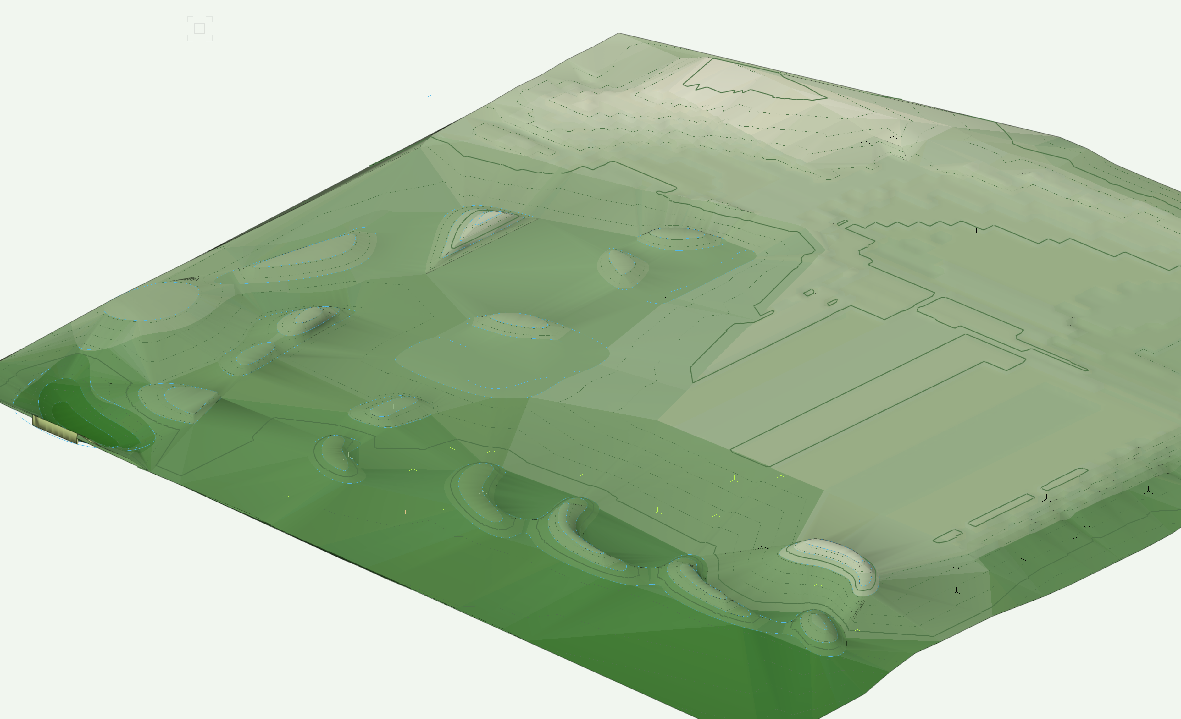
#1 - You don't need to use existing contours for your existing conditions when you have been supplied points.
Just grab the points and make and existing site model from them.
Next, draw a grade limit around your proposed contours to define the extents you will allow Vectorworks to resolve the grade.
Add your 3D Polys representing your proposed contours to the Site-DTM-Modifier class.
Set your model to Display proposed in 3D and 2D.
Update the site model.
You should then see something like this which features burns and swales fitted to your proposed contours.

The file you posted shows something similar at the far right, but your existing contours lost their z elevation. This happened sometime around your example named "PROPOSED SITE (CONTOUR EDITED)". Another reason not to use/generate contours when you have points, you can make mistakes without realizing it.
Flip your file up into Front View and you will see what I'm talking about... you contours are suddenly flat.
Attached is a fixed version of the file for reference.
-
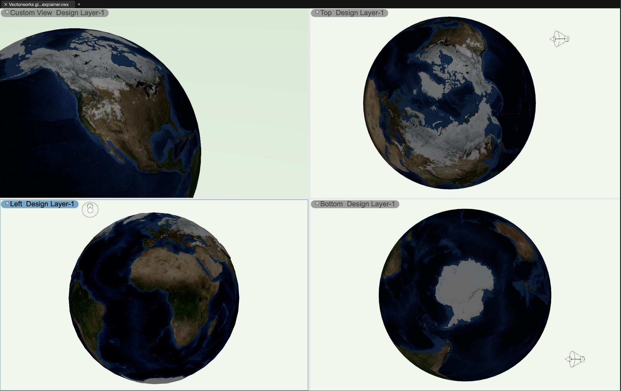
I've always been partial to globes with a bit of raised relief myself...
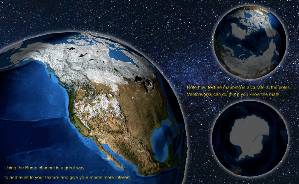
Just make a Vectorworks sphere.
Then, make a texture from an image. The best results use an image made from equirectangular projection.
Finally, texture the sphere using spherical mapping.
The trick to accurately scaling and placing the texture involves Pi and the length of a 90 degree arc based on your model size.
The previous examples here by @Kevin K and @VIRTUALENVIRONS may be salvageable in that regard, I don't know where they got their textures.
And yes, I did do it in Vectorworks...

-
 1
1
-
 1
1
-
-
38 minutes ago, nicovlogg said:
When I add these in 'Proposed Contours', the model does not change.
Post the file so we can see what you did here. Likely the source of your issue.
-
I’m glad I’m not in the software business 🙂
-
1 hour ago, aage.langedrag said:
All geometry that Landscape architects works with that is to be built should use curves with whole numbers of radius. No curves shall be divided into lines. The problem arises especially in our company when geometry is imported from other software such as dwg. All curves are then divided into countless lines, which is useless and makes the model very difficult to work with. When this happens, I ask those responsible to re-model the geometry in Vectorworks so that all curves and arcs have geometry that can be adjusted and changed. All arcs then only consist of three points, start, middle and end. This is where it is important to further control geometry with Simplification
Tolerance.
The first image shows geometry that is correct, while image 2 shows precisely the problem that the geometry has come from AutoCAD 2D. Sloppiness and inaccuracies that have worked for drawing production in 2D do not work when we work in 3D and BIM. Geometry must therefore be modeled again or changed so that all curves get the correct shape. Why should we allow mistakes to continue in the first place? 3D and BIM are also helpful in making us more precise and accurate.
I have to disagree with a lot of this. Not all curved landscapes must be made from arcs with radii, it’s perfectly acceptable to use curves like beziers and such if your contractor knows how to build them. Is the “problem” you are experiencing with importing AutoCAD splines and arcs into Vectorworks due to bad import settings or perhaps poorly drawn AutoCAD? I don’t have these problems with well made AutoCAD files, but I used AutoCAD for 20 years, so I know how it works.What makes “bad” geo inside AutoCAD? Drawing without tangency…not using snaps…Offsetting splines to create parallel edges… as it turns out, a lot of the same bad practices people have in Vectorworks. Understanding geometric construction, especially with complex curves, is a dying skill. It’s easy for people to blame their softwares, it takes experience and craftsmanship to make things… even in the digital world.
-
1
-
-
7 minutes ago, MGuilfoile said:
I assume that those persons using VW2022 purchased a perpetual license, otherwise you would simply upgrade to VW2023 or VW2024, yes? Assuming that is the case, the reasonable--and I feel honorable--thing for VW to do is send a perpetual version of VW2024 to those users. That is the thing about this word "perpetual." Having worked in and for museums most of my career, I can tell you that an accessioned object at a museum is generally accepted with terms that the institution care for the object "in perpetuity." But neither side can predict the future. There may be fires, floods, political unrest, or uncontrolled third parties who change their software in unpredictable ways. And regardless of the calamity, a reputable museum will do everything possible to secure its collection. The reputation of the institution is, in many ways, established in how it reacts to these types of unpredictable events that test it. How do they measure up? Reputation is not only an important thing, it is the ONLY thing that matters. It can be lost in an instant, but take decades to recover--if ever. VW might want to think about that as it considers its options regarding the non-working 2022 perpetual licenses out there. It sounds like neither party is at fault, so what to do?
So, here is what I would suggest to Vectorworks: Live up to your promise of delivering a "perpetual" product. Give users of perpetual 2020 through 2022 versions that do not work under Sonoma, a perpetual version of VW2024. Even though it's not your fault, you should live up to your bargain of "perpetual" regardless. This may not mean forever, but, really, I think a reasonable person would say two years is far too short of a term for a software to work. I'd say something more like five years, but whatever it is, put it in writing.
Just my opinion.
MH Brown
That’s a hard position for me to support, especially in the technology space. If I were electing to stay on a previous release in perpetuity, the prudent thing to do is to maintain that vintage of hardware and OS in perpetuity as well. The user has the choice here and if they want fancy new OS features, they should upgrade their other softwares accordingly.
I have not upgraded to Sonoma yet because I like my software to work 🙂 I don’t understand why people feel compelled to run the latest of everything and then expect it all to work…. New Release = Beta Tester in the software world.
-
The easiest way to do things is usually the 2D way...
...with some helper geometry to snap to automatic 3d working planes.
You just have to draw on different planes and then turn your 2D work into 3D Polys.
Here's a video, easy peasy.
-
3
-
-
2 hours ago, gfyfe said:
From what I've read, this is generally done via viewport annotations for most people. Is it possible to reference the floor plan while detailing the elevation in order to draw in cabinetry etc. accurately as it's drawn in the floor plan?
Any tips / workflow suggestions for interior design drawing are much appreciated!
There are several ways to go about this.if you are using sheet layers…
You can place a viewport of the plan view above your interior elevation. As long as you have “show other objects…” mode active, you can see and snap to that floor plan while working in the annotation space of your interior elevation viewport.If you prefer to work in the design layers to layout your work, you can make a design layer for interior elevations and place the viewports there. Then, you can work in the design layer to embellish your elevations. You can make viewports of cropped portions of the plan and move/rotate them as required to suit your elevation. Personally, I find this to be the fastest method, as you can move between elevations quickly, option/drag to copy elements between them, and arrange your views much easier. Then, you just make a single viewport to your sheet layer for an arrangement of elevations. Vectorworks performs faster too when there are fewer sheet layer viewports to update.
-
58 minutes ago, TeeMuki said:
The dream file for sharing would have symbols as blocks, then surface borders as polylines and surface areas as hatches.
When we export Hardscape- and Landscape-objects into dwg-files, they convert into blocks. We would definitely prefer that they would convert to polylines and hatches.
That's how it works currently.
Symbols export as nested blocks.
Hardscapes export as blocks composed of a hatch, a hatch polyline boundary, and an object polyline boundary... all of which is classed.
You can get rid of the extra polyline boundary by deleting the objects on that class.
Of course you need to be organized in Vectorworks in regards to how you use classes for this to be a quick and easy process.
1 hour ago, TeeMuki said:Which settings should we use that they don't convert into Blocks?
You probably want groups and symbols to convert to blocks. The first level of block is named "parametric object..." You can filter a selection set in AutoCAD for blocks named "Parametric object*" to select them all and then explode. Plant export first into containers named "parametric object...", once you explode them to their nested block, it is named after the plant. Most objects follow the same logic. So, exploding that first level container symbol is a one step process for you entire drawing. The next step in AutoCAD is to simply filter for objects the container class(es) for your hardscapes and delete that. You will then be left with an outline and hatch for your hardscapes.
It's like a 2 minute process for the largest of drawings, when you have an organized class system in Vectorworks.
-
1
-
-
must resist switching to 2024....
I just experienced this great update today while coordinating a set of plans with 6 different enlargements used across 24 sheets. Salvage, Hardscape, Planting, and Irrigation.
Nicely done Vectorworks! I look forward to doing more with this tool.
-
2
-
-
42 minutes ago, grant_PD said:
So to @Kaare Baekgaard's point, I read that as what he is wanting.
His post is nearly 9 years old, perhaps things have improved a little?
@htranbos necromanced this thread and had a different concern.
I don't know how C4D does things, but Vectorworks has a rudimentary stacking of transparency that actually exports pretty good, see video.
What would be nice is to have by object and z-buffer exporting, but I can't fault VWX for not having those given it's purpose and audience.
-
1
-
-
2 hours ago, Ed Wachter said:
Not to be too fussy, but do you know why the hatch in your Hidden Line rendering is a slightly different pattern than what appears in the Shaded version? Our office has struggled to maintain a consistent pattern between the two render modes.
Because Vectorworks made that particular texture and hatch. I guess the person who made it must not have been paying close attention to the details, you see that from time to time in the Vectorworks library. You can make them match perfectly with the right hatch design.
-
2 hours ago, grant_PD said:
Doesn't let vw off the hook for not providing alpha transparency export tho.
Vectorworks does export the alpha channel though...
-
- Popular Post
- Popular Post
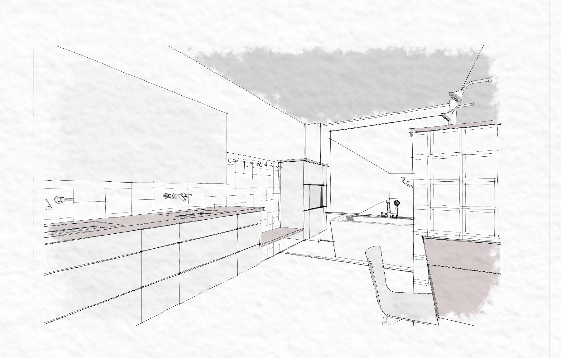
...for making funny thank-you cards for clients.
Congrats on your bathroom remodel from the team....


-
4
-
 2
2
-
5 hours ago, htranbos said:
When I open it in photoshop and place it over a black gradient background. I can see jagged edges around the image.
Does anyone know how to fix this?
You aren't going to eliminate it in Vectorworks, but as @mjm mentions, increased resolution can help diminish it.
The correct way to fix it is to edit the Alpha/Layer Mask inside Photoshop. This will preserve the quality of your image while allowing you to change how the edge of the mask looks. Lots of tutorials on Youtube I imagine. This is a common thing and a skill that should be learned if you compose boards and do a lot of raster work. It's especially helpful if you make your own image props or fix the ones that came with VWX.
-
1
-
-
17 minutes ago, Ed Wachter said:
I appreciate your time and help!
My pleasure. That was an interesting workflow to look at.
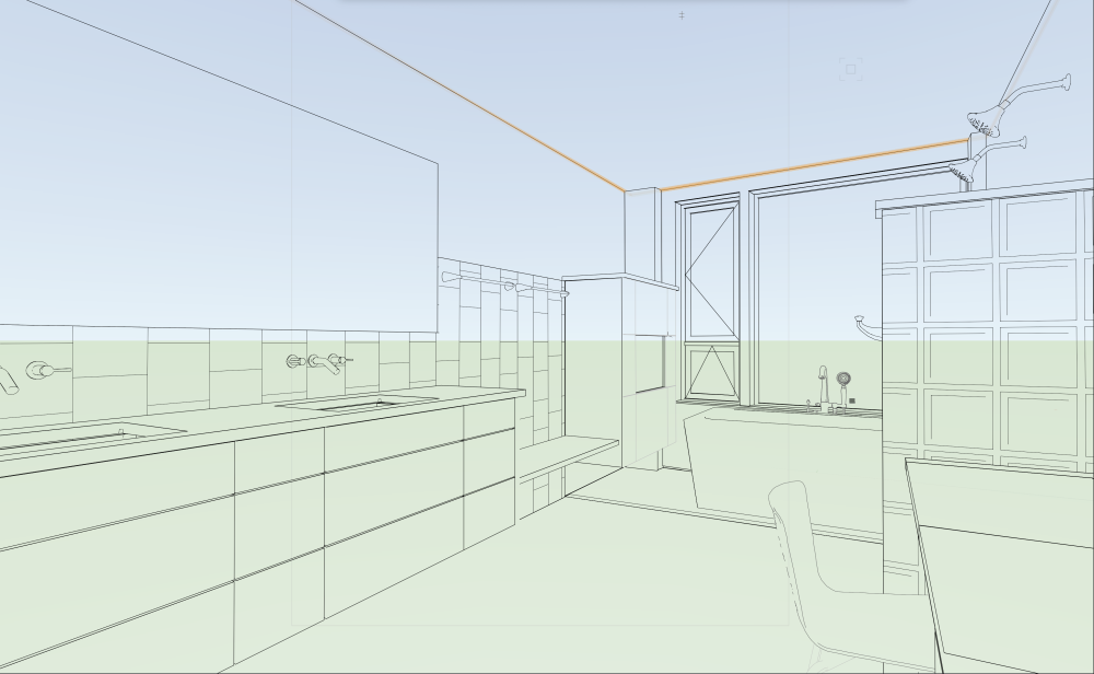
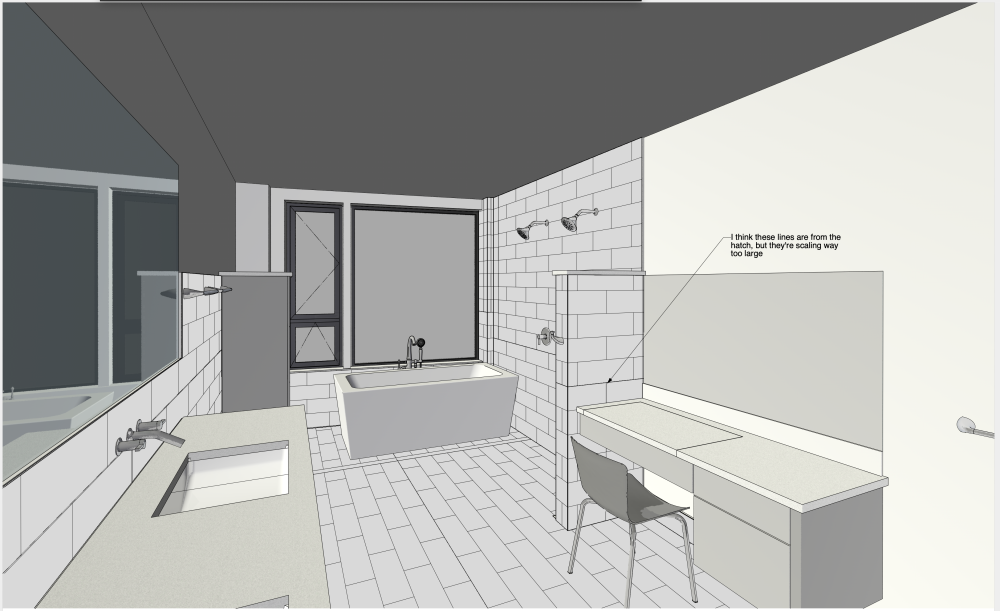
You might want to look into using Textures that have hatches built in for hidden line rendering. That would save you so much time. Then, you could use staked viewports to combine Hidden Line and Shaded (or any colored rendering mode) to create dramatic effects.
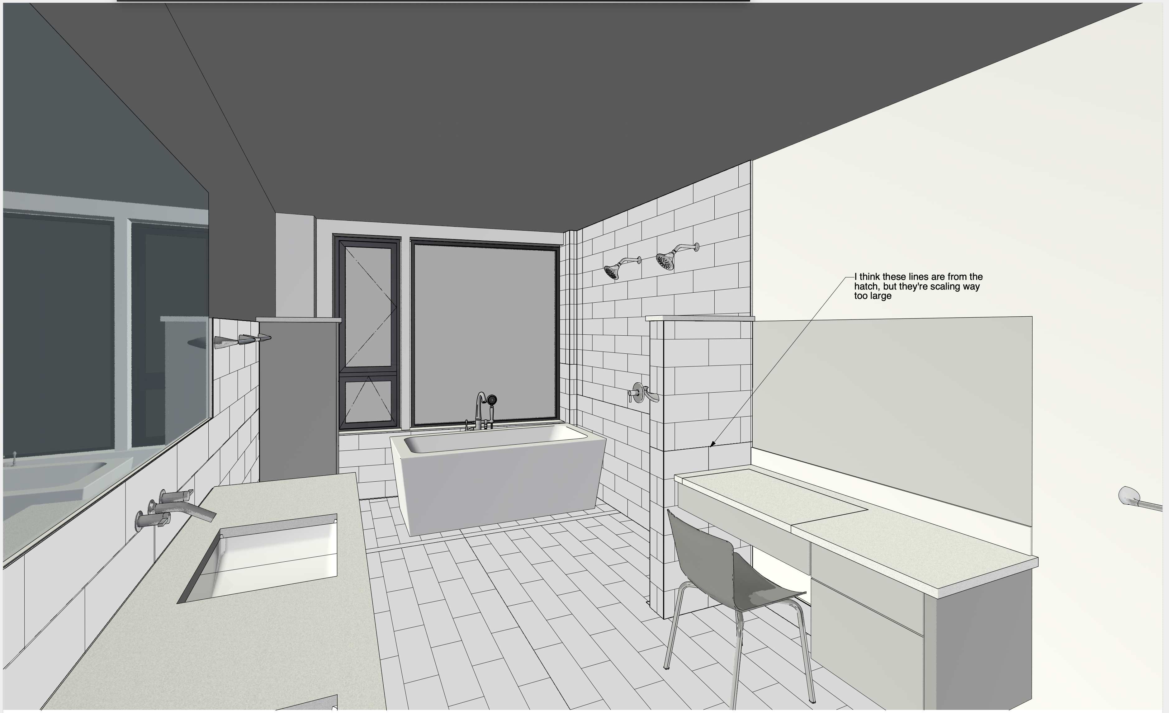
Here are two extruded rectangles with one texture assigned to each. Note how the Hidden Line rendering shows a line hatch and the Shaded rendering shows a texture. This is so much easier to manage than making those 2D polys and assigning hatches, especially when changes occur.
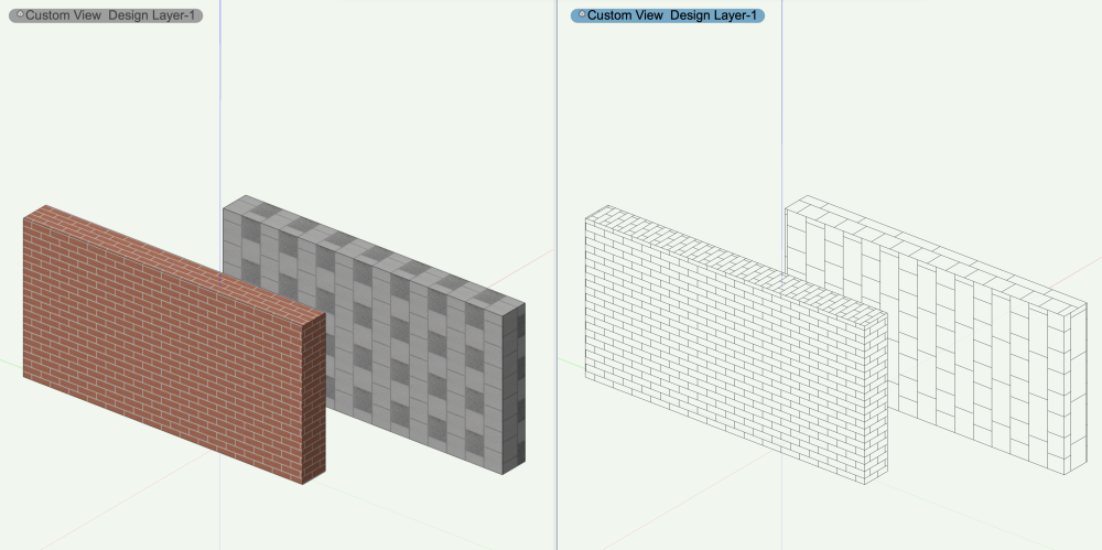
Here is the same technique applied to your project:
The CMU and Glass block textures used here are built into Vectorworks, but you could make your own too....
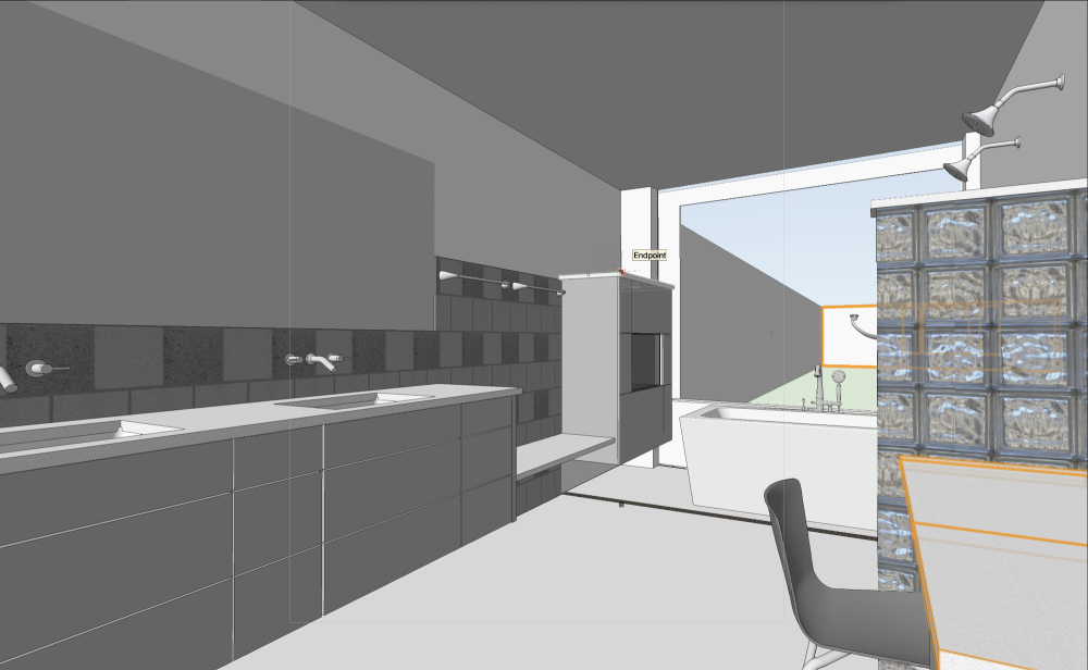
The same scene in Hidden Line Rendering, note the hatches are generated from the hatch built into the Texture applied to a single object. No need to make those 2D Polys anymore 🙂. You would just need to make textures with associated hatches and make sure they are sized correctly. Things would get fast and easy from there.
-
2
-
-
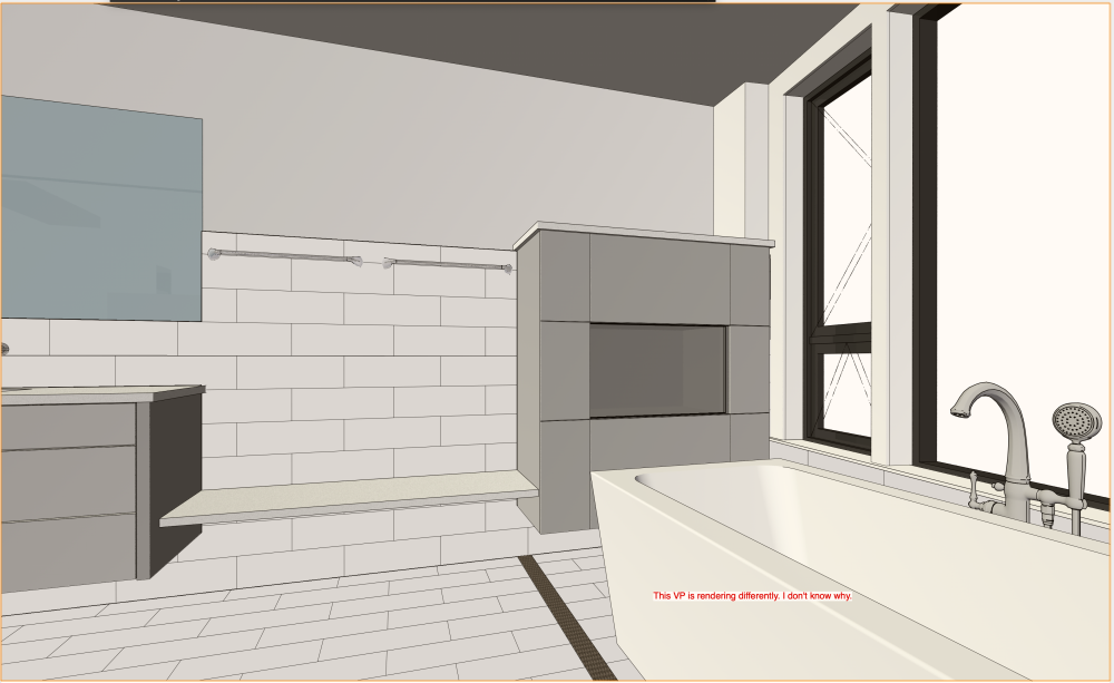
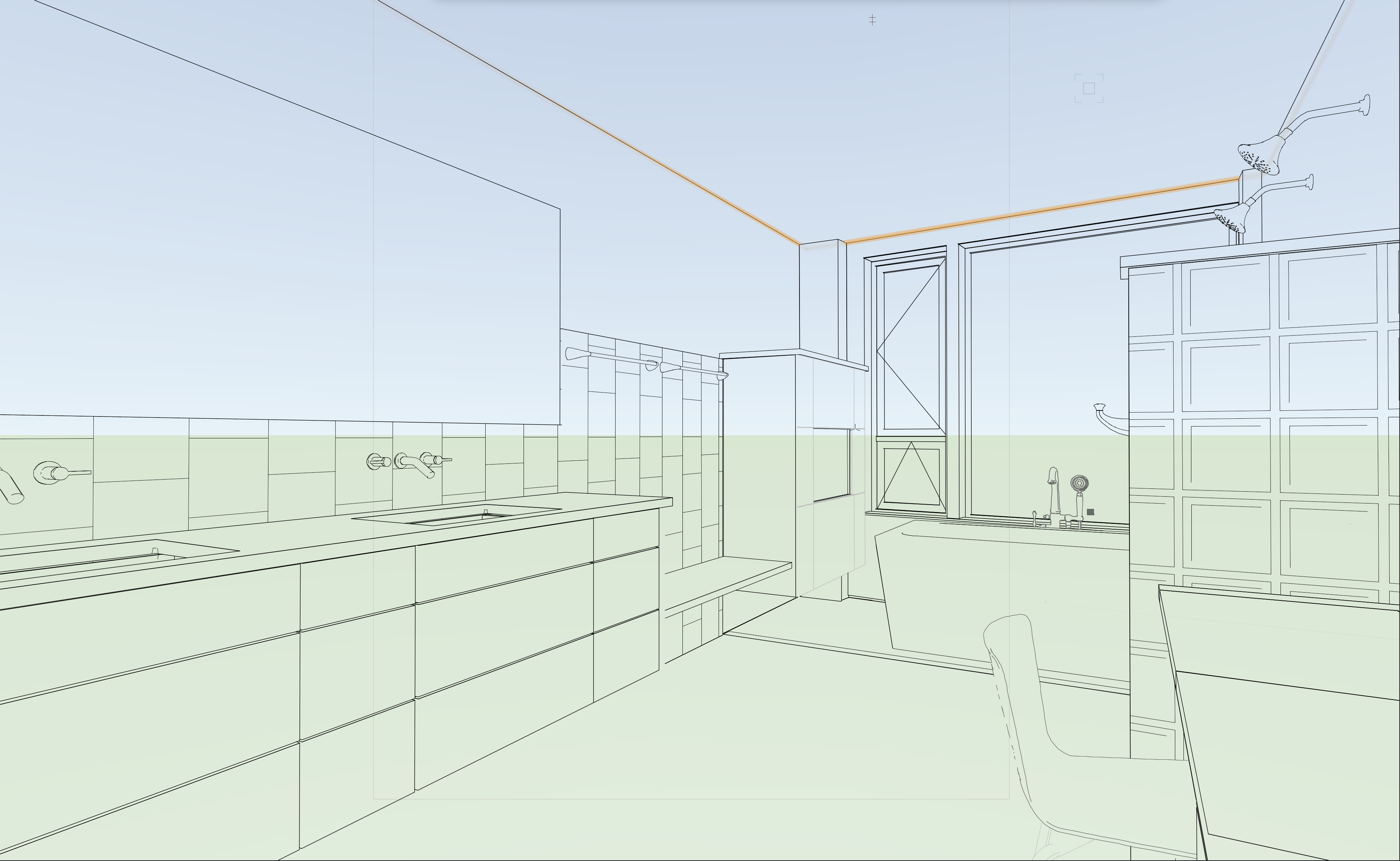
If you want the same results between different viewports, you have to use the same settings for the Layers, Classes, Rendering and Lighting settings.
Sheet B4 is not using Foreground Render = Hidden Line, so your hatches don't show up. Once you fix that, your Advanced Properties are not set to Black and White only on this viewport, so you get colored lines. Correct that and sheet B4 is great.
Sheet B3's camera position is coincidental with the wall behind the camera, which is incredibly bad luck and amazing that it occurred in such a way for the graphics to display this way. You can remedy this by adjusting your view.... or Pro Tip - put the coincidental geometry on a different Design Layer and then turn it off in this viewport. Think movie set when it comes to rendering these tight interior spaces, just remove some walls 🙂. Just remember, if you do that latter, make sure you turn that design layer on where it may be needed in other viewports. Clip cube in future versions of the software might be helpful, I don't think it works in 2021 the same as later releases.
Fixed by hiding the "Wall Behind the Camera"
-
1 hour ago, Ed Wachter said:
@Jeff Prince Ooops! Yes, those are 2D polygons in 3D space. Regarding how they appear in VPs, now some VPs display them correctly; others do not.
Is there a way for me to share the file with only you? I'd also like to eliminate our titleblock, or at least our stamp and signature, before I send our VW file, but I don't know how to eliminate the TB and VW won't allow me to delete the class that contains our stamp and signature.
Ed
Backup your file first and make a copy to send. Then, you can delete the sheet layers and design layers that are not needed for a discussion and purge it. That should get rid of things quickly. You can post it here and others can see it or you can send it to me via a private message. -
2 hours ago, Ed Wachter said:
We use 3d Polygons with a hatch
Are you sure about that? Hatches are a 2D graphic that can be applied to 2D polygons or 2D polygons that have been drawn in 3D space... not typically 3D Polygons.
Post the file and more detailed help can be provided.
-
7 minutes ago, Carol Reznor said:
If this happens again, the way to get rid of it is to: in the OIP
1. set the configuration to Aligned
2. click on Update alignement so the candy-can-stripe disappears
3. then you can change the configuration to another configuration without having the candy-cane
cheers
that doesn’t actually fix the problem when the issue is in the hardscape style. There seems to be something in the tool that holds the warning until you switch styles. Seems like a bug. -
If you post specific design problems here on the forum, you'll get plenty of people here to help you get on the correct path to making things like decks. You will have a couple that will lead you astray too 🙂. Those coffee breaks are good for scratching the surface and making you aware of things, but there's no way they can cover everything for every industry. You have to watch some of the architecture ones and then apply what you have learned to your specific design problem, like decks.
1 hour ago, Cody Worthman said:I guess part of the problem is the sheer amount of tools and commands available inside the program compared to the educational material available: I don’t what I don’t know. Sometimes you have to discover that a command/tool exists.
All of these big BIM and CAD packages take a long time to become good at. If you are also learning your profession on top of it, that's a lot of brain exercise. You'll get there, just keep plugging away. You can always hire a trainer to teach you advanced workflows too.
1 hour ago, Cody Worthman said:You’d think having more in depth tutorials online would be good for marketing and helpful for converting users from structure studios or Sketchup to Vectorworks.
As a longtime Autodesk client, I can say they did nothing for landscape architects for over 20 years. It was one of the reasons I left the platform. I'm pretty impressed by what Vectorworks has done with the University offerings. While there aren't many good VWX Youtube channels that are able to keep up with this constantly changing program, the Uni and the Forum do a pretty strong job of making people into experts. It just take time like any other program. The best way to get results out of the forum is to post specific design problems you need help with. Sketch something by hand and say "help me make this _______" and you'll get a ton of help. On the flip side, I see a lot of people post questions about how to make things without providing any context, a design sketch, an image, or a rudimentary VWX file.... those folks tend not to get much help because most of us aren't good at reading minds... yet.
1 hour ago, Cody Worthman said:At times, I wish had gone with Revit
No, no you don't 🙂
Maybe if you were an architect, building services engineer, or fabricator.
Landscape Architecture in Revit is still a bit of a joke. Maybe one day it will be useful and affordable, but it would have to be through a 3rd party.
For those of us in landscape, we really only have a handful of productive 3D + CAD tools. I'm not allowed to mention them here...
-
3
-
-
3 hours ago, Cody Worthman said:
As great as the deckworks plugin tool would be, I would be happy to know best practices using existing tools so I can represent a wide variety of situations including: steel/composite/aluminum framing, tile on pedestal decks, or even sleeper system decks.
We clearly have the tools to create decking structures for unique situations, it would be great to see clarification for how others are working.
In your other thread, I mentioned I build decks just like any other architectural element and by using a variety of tools.
I don't think you are going to get anything beyond that from Vectorworks staff.
My advice is to learn the tools (wall, slab, stairs, railing, etc.) and put them into use.
Decks are basically just buildings without interior cladding and insulation 🙂
Also, don't be afraid to hack the tools we have and use them inappropriately.
Example: I use the site modeling tool for all kinds of deviant purposes to quickly generate irregular surfaces, and even building roofs on occassion.
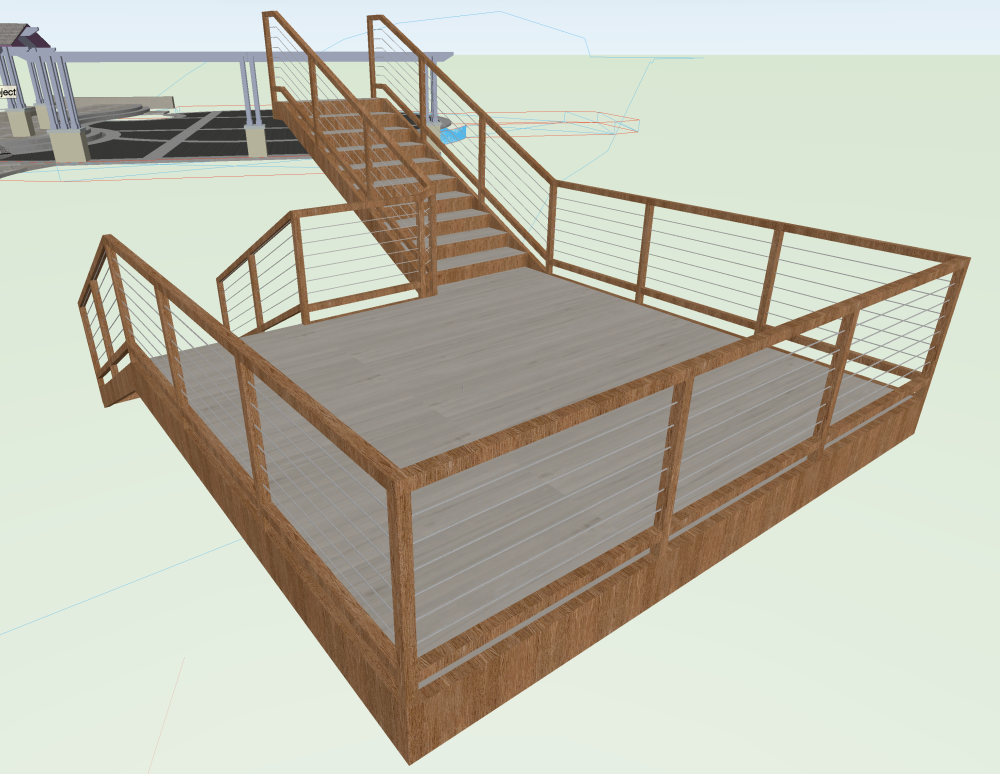
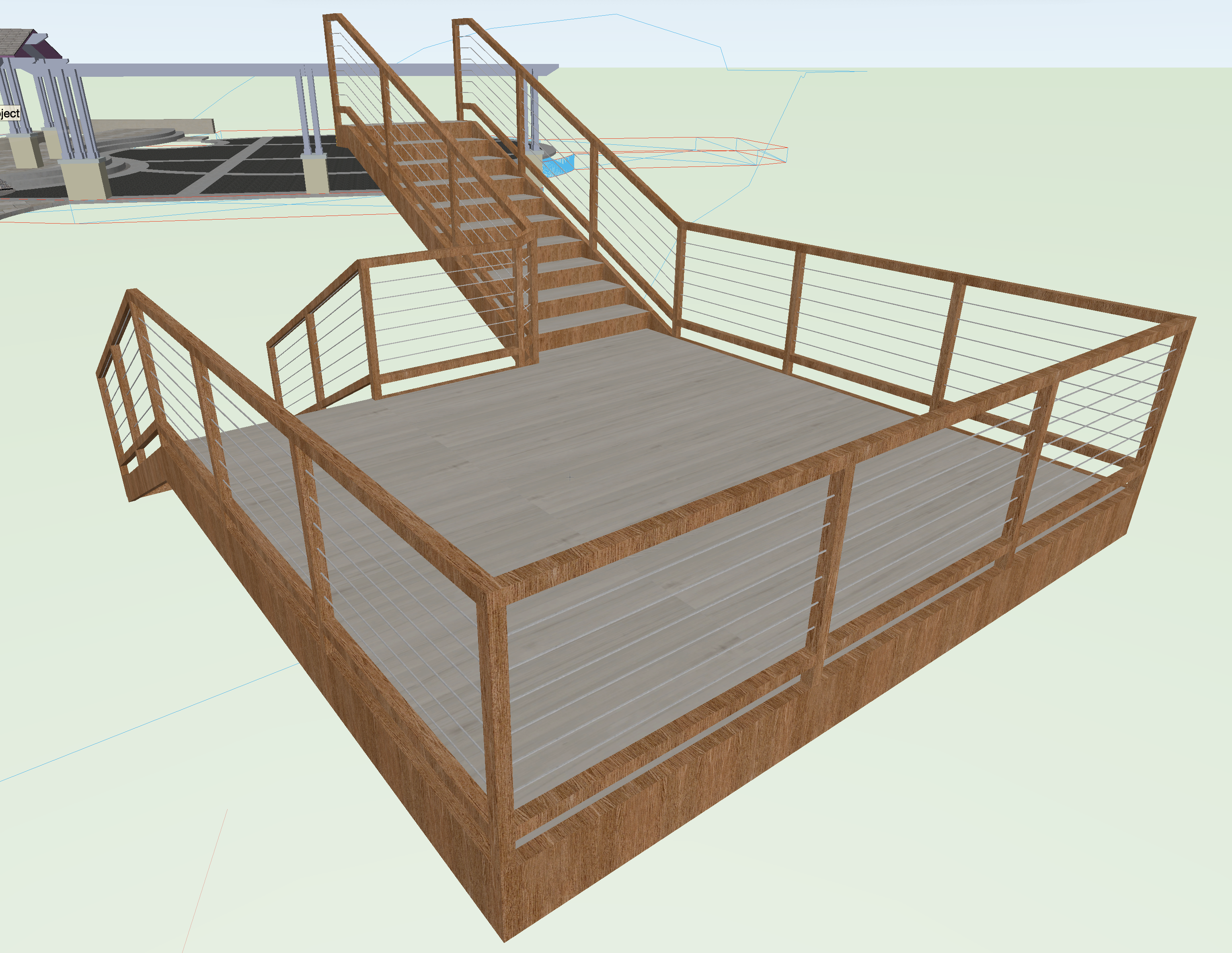
Here's a fairly simple hack....
If you are doing simple rectangular decks, the stair tool is actually a very quick way to generate the basic finishes and railings.
You would have to add columns and structure to it, but that's pretty easy using the Columns and Framing or just simple Extrudes.
-
2
-


'Proposed Contours' not working as expected in Site Model
in Troubleshooting
Posted
Well, I suppose if you mean all of your existing contours have the same elevation of -5800, then I suppose your are correct 🙂
See this video for an explanation of why your model is misbehaving...
You are missing grade limits in that image where your contours look like vertical sided pits.
Site modeling is only as good as the data you feed it.
It's easy to get lost in all of this, happens to the best of us.
Break it down into simple steps and check your work if things go wrong, usually the issue will be evident.