line-weight
-
Posts
3,755 -
Joined
-
Last visited
Content Type
Profiles
Forums
Events
Articles
Marionette
Store
Everything posted by line-weight
-
I fear you may be in for a long and tedious process... but just in case it helps at all, see the second post here - something I hadn't realised was possible
-

drape paving over a DTM ideas for Twinmotion output?
line-weight replied to jnr's topic in Site Design
it does for me..... ? -
Does VR have genuine advantages over just a 3d view, for the purposes of editing?
-
+1 more
-
drape paving over a DTM ideas for Twinmotion output?
line-weight replied to jnr's topic in Site Design
I've had some success using the 'spoil pile' site modifier to create kerb lines - you can draw as polygon in plan, and it'll offset the surface of the DTM by whatever height you specify. I've done it using it to offset pavement (ie sidewalk if you're in the US) areas upwards but you could potentially use it to offset roadway areas downwards instead. I've experienced some bugs using it in VW2018 but it's just about usable. -
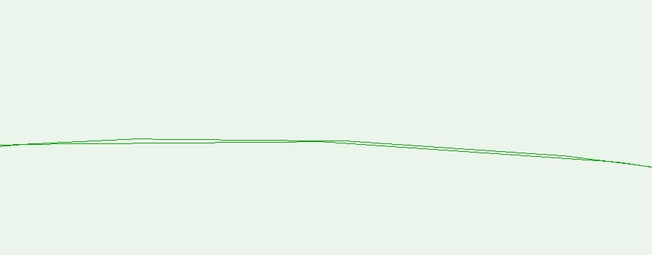
I just tried making this NURBS curve into a 3d extrude Then 'extract edge' to get the highlighted edge. It looks ok zoomed out but when you look closely it looks like this Two faceted curves that don't quite match each other.
-
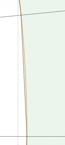
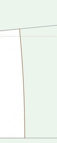
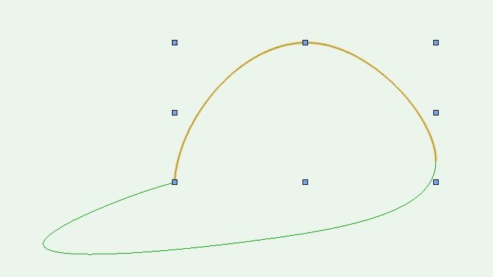
Going on a bit of a tangent here... but I've realised there's something that's very tricky to get right even if you aren't worrying about the faceting. The attached image is in wireframe view so there is no faceting going on. It's a top, orthogonal view. Say I have drawn the blue curve first - and it then becomes part of the geometry of an object, the edge of a table, let's say. Now I want to draw the orange curve - I want it to follow that blue edge exactly. As you can see, it's easy enough to get it nearly right ... but if you want to get it exactly right, then the only option is to take the original blue curve, and cut it back somehow. Is that correct? Which is something you can only do if you've kept that original curve somewhere. If the object is something that has gone through a process of some subtractions, extrusions and so on, the original curve might not be easily accessible. So if you are doing this stuff properly then presumably you have to be always thinking about keeping track of the original geometry somewhere. I imagine these issues would come up modelling something like that boat. Or is it somehow easier in Rhino?
-
Yes, that all makes sense to me. I'd sort of assumed that in principle, that's how it would work anyway (ie pre 2020) but sounds like it's not necessarily. So in pre 2020 versions, VW is calculating a load of facets even if a thousand of them are within a single pixel on screen?
-
Where's a marionette network supposed to "live"?
line-weight replied to line-weight's topic in Marionette
Thanks - all understood now, I think. -
Where's a marionette network supposed to "live"?
line-weight replied to line-weight's topic in Marionette
Hi @sbarrett and thanks for your reply. Following your instructions I've managed to remove a menu command, and also re-name it by re-saving it as a new menu command with the name I want. I note that it seems to be necessary to quit & reopen VW for these changes to take effect. Regarding using a network without making it a menu command... whether it's in the form of a symbol or not, the idea is that you place it into the drawing space of whatever you're wanting to use it to work on, and then delete it from there once it's no longer needed? Once it's in the drawing space, what does and doesn't it act on - does it act on anything in that file, or just on that design layer? -
yes, as noted further up the thread, increasing the number of control points on the curve has no effect. Regarding NURBS curves and 'degree' settings - this is a separate issue to what is being discussed in this thread, but contrary to what that PDF document implies, it is not at all clear what 'degree' means in VW and how it is controlled. I explain this in another thread:
-
Thanks for taking the time to look at it and it would be good to hear if and when there is any progress. It strikes me that the faceting can be controlled by the various render settings which range from 'low' to 'very high', it's just that 'very high' is not high enough. Therefore is it possible to add an extra tier that *is* high enough? I assume that there are then potentially problems with the rendering becoming unmanageable but other elements are rendered in way too much detail.
-
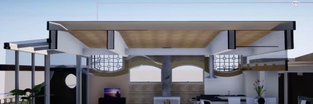
Looks like it also has some issues with sectioning elements that should be solid but turn out hollow - for example the roof, and roof beams here That's perhaps dependent on the geometry that it's given, so not Twinmotion's fault... but maybe means it can't solve this hollowness problem which is often encountered in VW?

-
What's the Muntin tool? (By the way it would be nice if region-specific versions of VW could use the correct terminology for building elements. In the UK we don't call these muntins; they are glazing bars. It adds an extra level of confusion to the options in tools if you also have to go and find out what unfamiliar terms mean. Not only are we disallowed the superior window/door tools that users in other regions have access to but we have to decode north american terminology used in the permitted, substandard ones.)
-
I often find it's easier just to model it from scratch instead of trying to fight the system, for this sort of thing.
-
Where's a marionette network supposed to "live"?
line-weight replied to line-weight's topic in Marionette
Thanks @Pat Stanford Since my initial post I worked out how to alter the inputs to the network so that it would act on a selected object when used as a command from the menu. Which does the job for now. Would still like to hear what the official advice is though. Also, now that it is in my menu, I'm not quite sure where that command actually 'lives', or how to get rid of a couple of test ones that are now in there too. -
Thank you. I've attached an example file. If you look at the sheet layer I've tried to make obvious the issues. facetingproblems.vwx
-
Pretty much complete marionette beginner here. I want to use a marionette network to carry out an operation on various objects in an already existing drawing. (It's the one linked to in @Marissa Farrell' s post here https://forum.vectorworks.net/index.php?/topic/45566-divide-polyline-into-segments/&do=findComment&comment=232266 As I understand it, I have to copy&paste the network into my drawing file. But where do I put it? For example does it have to be on the same design layer as the object I want it to act upon? It seems I can paste it into the screen plane in which case it is kind of floating there in front of the objects I want to alter. Then I can use it, and delete it, and then re-paste it next time I want to use it (potentially somewhere else in the same file). I'm guessing this is not how it is intended to work though? Watching the video below I see that I can convert it into a menu command. I've managed to do that. It doesn't appear where the video says it will (Tools menu) - it appears in the 'New' menu. But anyway - now it's a menu command, am I unable to edit it, or get into it to change the inputs? https://youtu.be/VCdxp2eRCmc
-
That is very poor that there was no follow-up from VW, after you put the effort in to do those tests and explain the results. I think the conclusion for now has to be that VW is simply not capable if you want to deal accurately with complex curved geometry. I'm going to have to rebuild most of my viaducts using segmented paths. Thanks for posting the Marionette link above, that will at least make it a bit less messy and tedious than it would be otherwise.
-
That's interesting - although, I think it is a parallel problem to the faceting problem - the geometry of the underlying curve could be 100% correct but the faceting problem still exist, I think? Did you ever get a response from VW on that? I have raised other questions to do with these kinds of curves, for example here specifically to do with NURBS curves: I also spent some time setting out the issue but there was no response from VW at all.
-
Was the object you imported a genuinely curved geometry or was it segmented?
-
Extrude Along Path - why's my wall leaning over?
line-weight replied to line-weight's question in Troubleshooting
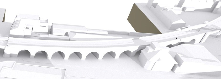
Guess what - it's Vectorworks so of course some other problem arose. I had some success building a number of viaducts which are curved in plan and rise/descend along their length. The problem is with the ones with more gradual curves, because VW seems unable to render these without introducing very large facets, making them look awful, and making it impossible to align/transition with other objects accurately. Discussed in another thread ( https://forum.vectorworks.net/index.php?/topic/55522-smoothing-nurbs-curves/ ) A potential solution to this is to change the NURBS path so that it is segmented with sharp corners, making the segments as small as necessary to give the appearance of a smooth curve. However it turns out that doing this causes the EAP to become hollow, meaning I can't subtract from it. I think that's a bug, if anyone cares.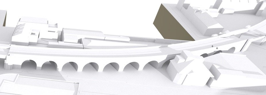
-
Thank you - I will have a look at that. I too have come to the conclusion that I am going to have to draw the path as a segmented line. This can be done by changing the degree of the NURBS path (to create more vertices) and/or converting each vertice to a corner type. Unfortunately this then results in the EAP object becoming hollow, which means I can't then subtract from it (for example to make the arches through the viaduct). So I'm now looking into using a loft instead of an EAP.
-
@Matt Panzer would it be fair to classify this as a bug? Effectively it would seem that there is certain geometry that is unusable/undrawable in Vectorworks. It's not something obscure that I want to draw - just something with a gradual curve. It looks like the only way I can do it is to manually draw it as a series of short, straight segments, that are shorter than the smallest faceting I can get VW to do.
-
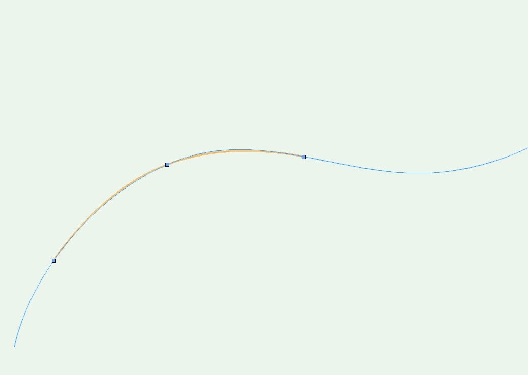
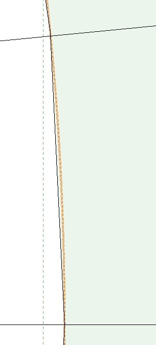
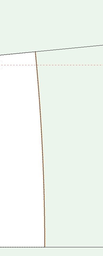
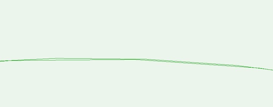
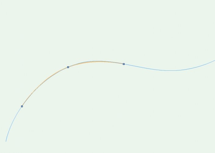
An observation: if I draw a circle and zoom in (in OpenGL) there is a facet approximately every 5.5 degrees (image on left, orange line is the 'true' curve) But if I chop that circle back, so it's an arc with a sweep of only 5.5 degrees, it's faceted into much smaller pieces (to the extent that you have to really zoom in to see it, image on right) So it seems to be related to length of curve as well as radius (at least, as far as a circle is concerned, not sure the same applies to a NURBS path)