line-weight
-
Posts
3,755 -
Joined
-
Last visited
Content Type
Profiles
Forums
Events
Articles
Marionette
Store
Everything posted by line-weight
-

2021 - Teaser Tuesday: Performance Enhancements
line-weight replied to JuanP's topic in News You Need
I'm guessing OpenGL maybe? -
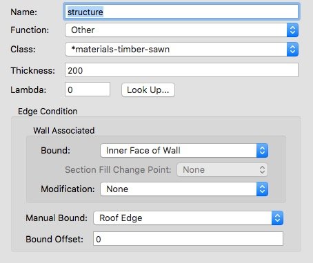
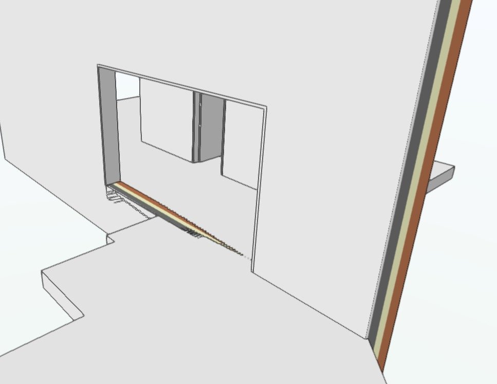
See attached file. Two roof face objects - each is associated with the two walls beneath it. They are the same except on one I've fitted the walls to the underside. The roof faces are set up so that their two lowest components are clipped by the walls, set to the inner face of the walls. But they are being clipped the wrong way around: they are present through the wall thickness and absent within the "room". Why is this (I have this working OK with other wall/roof combinations in the same model, from which I've extracted these elements)? wall_assoc.vwx

-
2021 - Teaser Tuesday: 3D Modeling Enhancements
line-weight replied to JuanP's topic in News You Need
You'd be better asking this question in the general part of the forum, I think. This thread is about an upcoming new feature that none of us have used yet! -
2021 - Teaser Tuesday: 3D Modeling Enhancements
line-weight replied to JuanP's topic in News You Need
Thanks. Having the edit history too would be a bonus. I actually already asked for it 4 years ago! -
2021 - Teaser Tuesday: Performance Enhancements
line-weight replied to JuanP's topic in News You Need
It's a little disappointing to hear that there will be no improvements to hidden line rendering. I find 3d performance not bad as it is. I can spin around my 3d models pretty smoothly most of the time. Most of my time spent waiting for VW to draw something, is spent waiting for it to draw hidden line viewports. -
2021 - Teaser Tuesday: 3D Modeling Enhancements
line-weight replied to JuanP's topic in News You Need
Looks promising - I use that subface mode of the push pull tool a lot so the time saving with what looks like a fewer-clicks method will be very welcome. One question though, a frustrating limitation of the push-pull tool is that when you use that sub-face mode, you can only "extrude" the sub-face, not "move" it, as per the "move face" mode. Will that remain the case? -
Best way to deal with structural wall/floor intersections
line-weight replied to line-weight's topic in General Discussion
Ah, I see. I don't generally use Auto Bounding, because I expect it to fail. But maybe I should try using it a bit more. -
Best way to deal with structural wall/floor intersections
line-weight replied to line-weight's topic in General Discussion
Do you mean by this, you just draw them so they intersect each other? -
Best way to deal with structural wall/floor intersections
line-weight replied to line-weight's topic in General Discussion
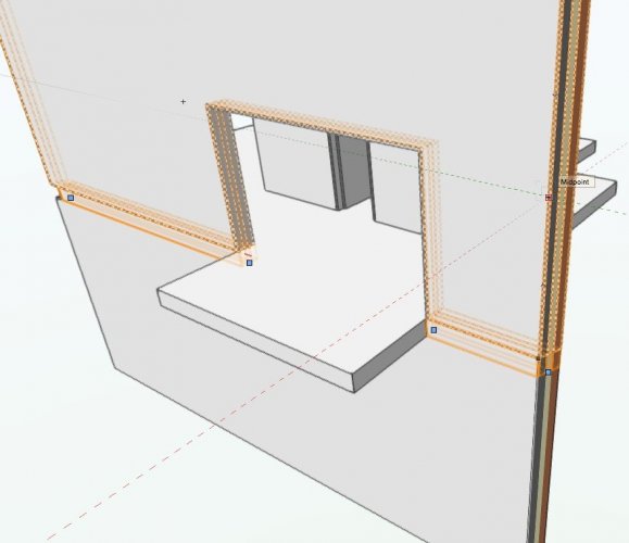
Thanks @zoomer I can see the logic of this approach. And the "invisible threshold" is a good way to make the door "opening" deeper than the door itself. The drawback is that it then seems inevitable that there will be lines visible at each threshold, in plan. At least at smaller scales, I like to be able to draw a floorplan that does not show any lines at door thresholds. I tried a version where the entire slab "flows" through the opening - so the invisible threshold is the same height as the entire floor slab. This is not really constructionally correct, as the floor needs either to be shaped around the jamb, or intersect with the jamb, but this workaround might be good enough for me in some circumstances. (My example is not intended to show a balcony, just a situation where a floor slab crosses over an internal structural wall, so an internal wall that is continuous vertically, and normally built before the floor slab is put in place)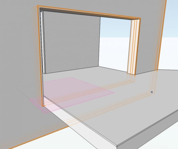
-
Best way to deal with structural wall/floor intersections
line-weight replied to line-weight's topic in General Discussion
No thoughts on this? -
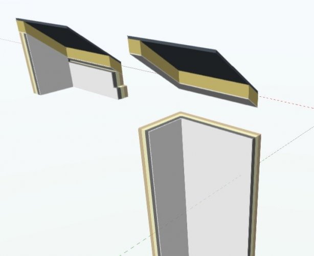
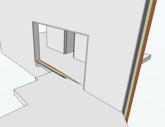
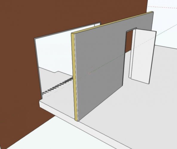
Here's something I come up against quite often. See attached example file and screenshots. When you have walls which span between floor slabs, as per the thinner wall in my example, VW knows how to deal with the threshold at a door opening. The floor is simply continuous. But it's different where structurally the wall is continuous through several stories - constructionally, the wall is continuous and the floors join to each side. You can draw it like that - different floorslab each side. That's fine until you want a door or opening through that wall, because when you introduce an opening, the threshold is then just a slice through the wall buildup. You can try and cheat and draw the floorslab continuous, like in my screenshots, but then you have that Z-fighting where the opening and floor surface are on the exact same plane. Sometimes I deal with this by making the door opening 1mm lower, which gets rid of that visual annoyance in OpenGL but that is messy, and it still isn't right in section. Shaping the floorslab around the opening profile makes the section correct where there's not an opening, but doesn't solve the other issues. Is there a "proper" way of doing this? The only way I can find is to build the wall in 3 stacked layers, one the thickness of the floorslab, (see my third screenshot) but that is very tedious and complicated. wallint.vwx
-
Yup as I discovered there's a bug with regular image backgrounds. One that's obviously not been fixed in the two years since I came across it.
-
There's no "best practice" or coherent workflow that VW is designed around, for architectural projects, I'm afraid. You kind of have to work out what works best (or least worst) for you and the type of projects you tend to do. One of the big issues is touched upon above: the "top-plan" concept sort-of works for certain kinds of buildings (large rectilinear ones with flat roofs) but falls apart for more geometrically complicated things. Then you can use the horizontal section approach - which has a separate bunch of problems associated with it. Vectorworks frankly is a big mess - but quite a flexible and adaptable one, which is why many of us stick with it.
-
Do you manage to work with multiple view panes?
line-weight replied to line-weight's topic in General Discussion
Yes, that's exactly what I get. This has been a problem for some time. I raised it in the thread linked to below (see the video there), but I'm pretty sure it has been mentioned by others earlier than that. Disappointing but unsurprising that 2 releases later VW have still not fixed this. -
Do you manage to work with multiple view panes?
line-weight replied to line-weight's topic in General Discussion
This is exactly what I've experienced and one of the reasons I've largely given up on multiple panes. Which version of VW are you on? -
Congratulations on annoying features :)
line-weight replied to Kaare Baekgaard's topic in General Discussion
VW is always trying to wind me up by sounding the "error" bell whenever this popup appears. It's like it is impatient for me to tick the "always do selected action" box because it's bored of asking me this question. Well, sometimes the answer is yes and sometimes it's no.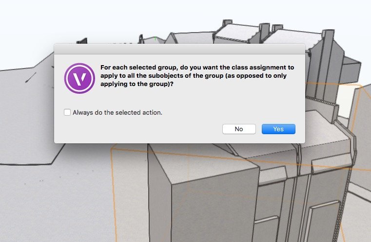
-
Do you manage to work with multiple view panes?
line-weight replied to line-weight's topic in General Discussion
That would make sense. Let's see. Where was this previewed though? -
Do you manage to work with multiple view panes?
line-weight replied to line-weight's topic in General Discussion
When the two panes are on the same screen like this, it's fairly easy to move between either of them, and the tool palettes. When a pane is on a second monitor, there's then a rather long journey for the cursor to make back and forth (plus my muscle memory keeps wanting to look for the tools in the normal position relative to the active drawing pane). How is this dealt with in other applications - do they repeat the tool palettes on the second monitor? I think that if VW did this, it might be easier to use in this way. -
Is VW drawing this roof face wrongly?
line-weight replied to line-weight's question in Troubleshooting
No comment from anyone at VW then? -
Do you manage to work with multiple view panes?
line-weight replied to line-weight's topic in General Discussion
It sounds like most people have come to the same conclusion as me - the floating pane configuration doesn't really work. That several people have said they do use something similar in other applications suggests that it's just a poor implementation in VW. Which is a shame because with a bit of effort it could surely be made to be more usable. -
I'm interested to know how many people use this in practice. Do you regularly work with multiple view panes and if so, do you have any of them arranged as "floating" panes and on another screen in a multiple monitor setup? I'd like to be able to work with two panes - one on my main monitor and one on a secondary monitor. Every time I try to do this though, I give up; it's just too awkward, I keep activating saved views in the wrong pane by accident and selecting tools is fiddly. On top of this there are various graphics errors that appear once you have more than one pane in operation, and it's my feeling that it causes various things to go wrong with the drawing too... floor slabs misbehaving, things like this. I'm still using 2018 so maybe some of these things have improved in subsequent versions. Or is it one of those Vectorworks features that is introduced as 95% functional and then never touched again, meaning hardly anyone actually uses it? Is it worth me persevering?
-
Is VW drawing this roof face wrongly?
line-weight replied to line-weight's question in Troubleshooting
Thanks, at least you are able to replicate it. It seems to be that the combine/connect tool applied to roof faces is unreliable/inconsistent, and/or there is something wrong with roof face objects themselves. -
Is VW drawing this roof face wrongly?
line-weight replied to line-weight's question in Troubleshooting
Any thoughts on this? -
Multiple Wall Types in single wall element
line-weight replied to jcaia's question in Wishlist - Feature and Content Requests
That was my thought too, as I think the door method would constrain you to symmetrical shapes. -
Multiple Wall Types in single wall element
line-weight replied to jcaia's question in Wishlist - Feature and Content Requests
VW simply isn't able to draw things like rooms in roofspaces properly in top/plan, especially when you want to show construction buildup even at a basic level of detail. For example in the drawing in the video there is an external finish and insulation shown in the dwarf walls that separate the eaves spaces from the room. Best in my view to draw them as horizontal sections, and just use solid modelling (or possibly stacked wall objects) for things like this. More flexible and probably no more cumbersome/time consuming to draw and edit.