


martinfdc
-
Posts
228 -
Joined
-
Last visited
Content Type
Profiles
Forums
Events
Articles
Marionette
Store
Posts posted by martinfdc
-
-
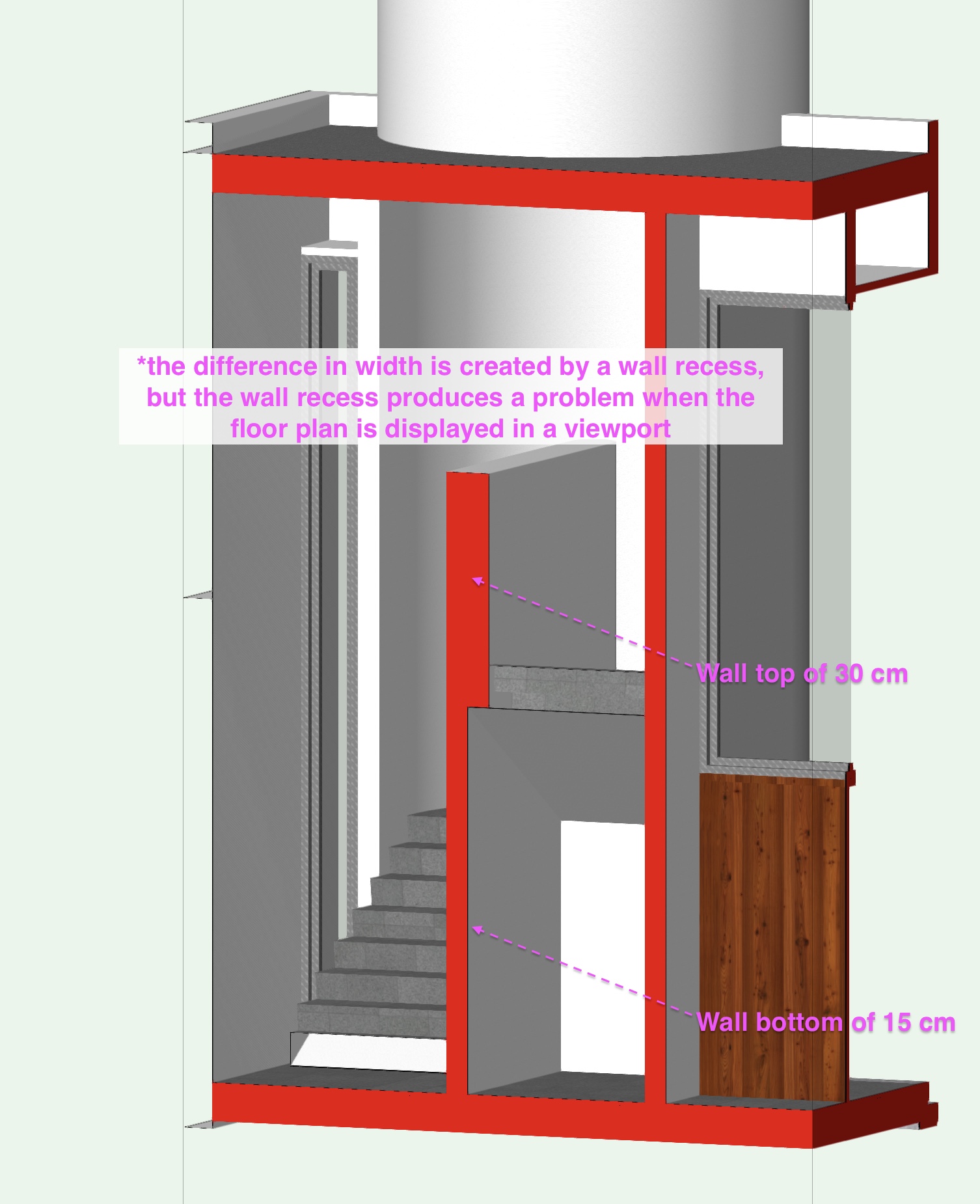
Thanks @zoomer, I ended up solving my problem another way though. I created the lower walls (15 cm) in the ground level layer and the 30 cm wall in the first floor layer and then I worked my way through with editing the bottom wall peaks of my walls in the first floor layer.
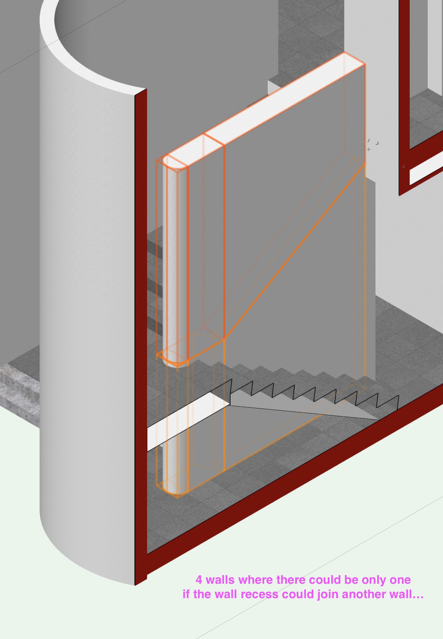
It's a pity that a wall recess can't join to another wall (at least in this case). The solution using a wall recess would be a much simpler one. Now I have 4 walls where there actually is only one wall that varies it width.
-
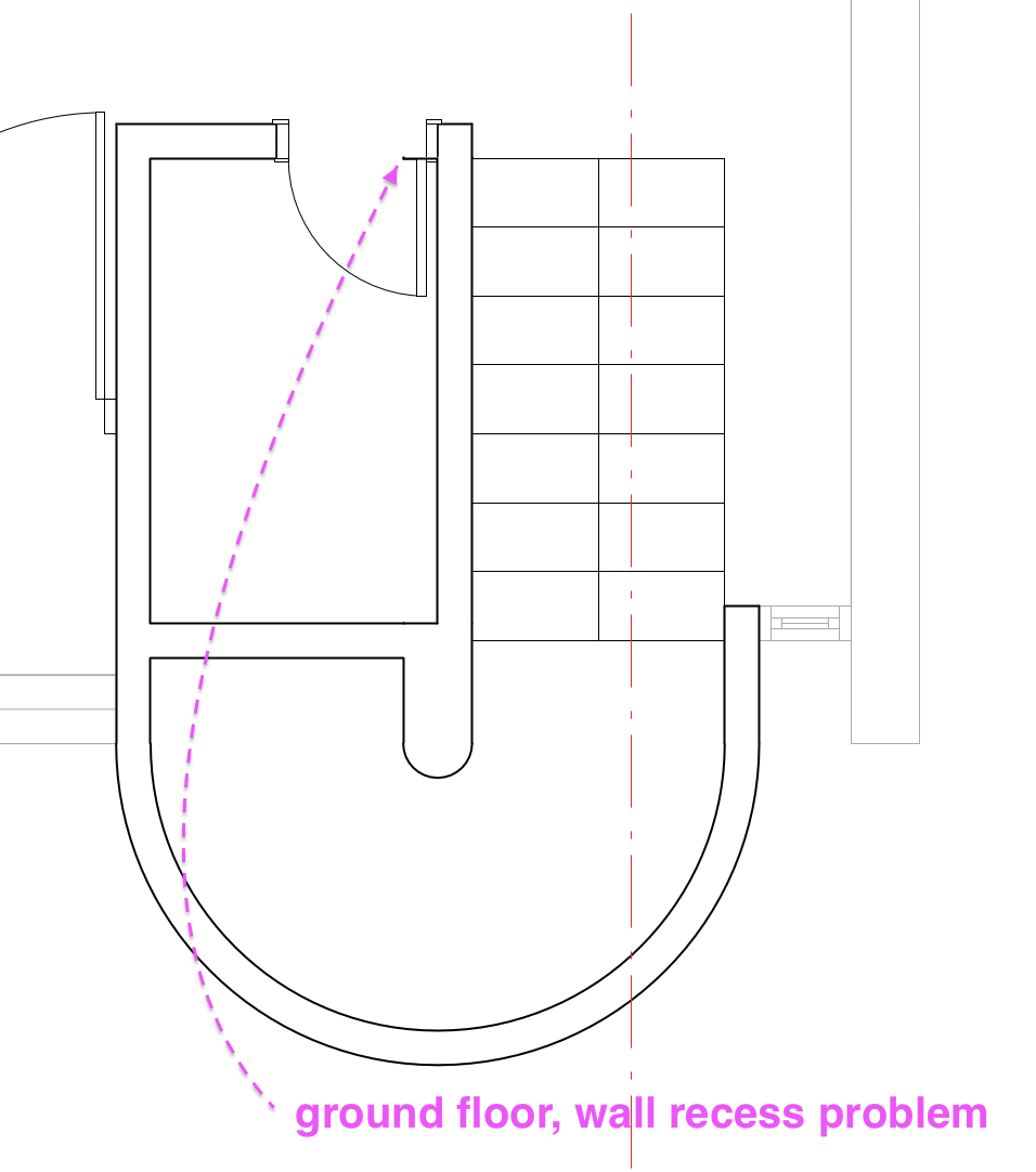
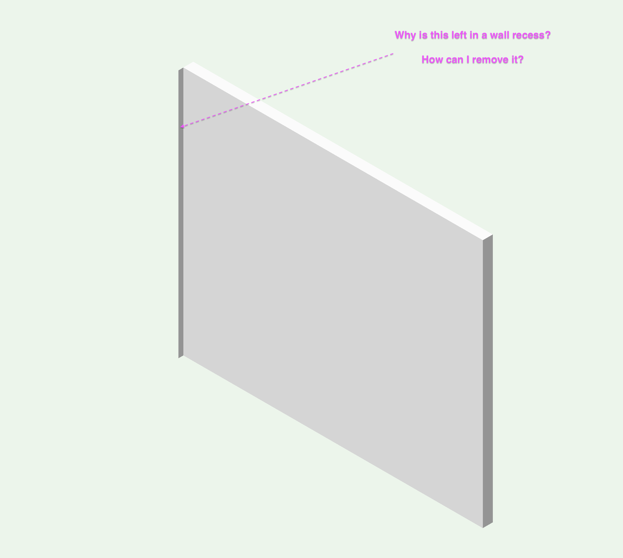
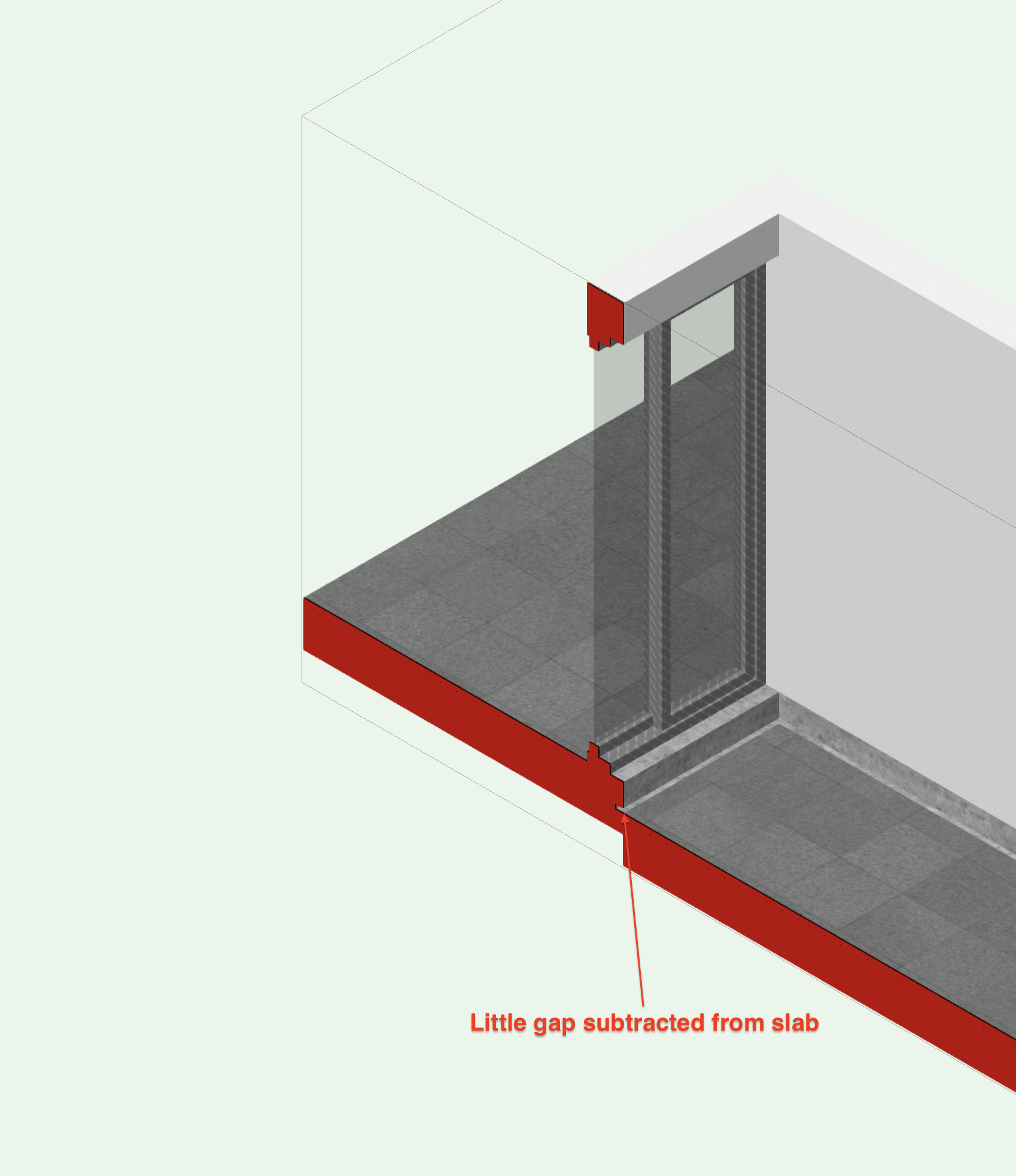
I'm actually asking the question above because I want to solve a problem I have with the way a Wall Recess is being displayed in my ground floor. I've tried everything to remove that tiny bit left of wall but I can't remove it. The wall won't join with it's adjoining wall (the one that contains the door...)
-
Hi,
Can someone please explain me why can't one make a Wall Recess that goes from the start to the end of a wall? Are there other ways to obtain a wall recess that goes from edge to edge? I don't want to use a subtract solid...
Or maybe it's possible but I'm just not finding the way to do it.
-
@Alan Woodwell, maybe the error that a line is shown between the two objects might be related to the bug in the thread below:
-
Maybe the error in this thread might be related to this bug too?
-
I'm using VW 2017. It's weird that you're getting like two intersecting textures. I get a clean break between my textures but I don't get what I want in my section or when seen from below. Probably this problem in general is related to the thread I mention in my next answer.
I attach two images and the result i get of setting the wall edge offset to the Center of wall core.

-
-
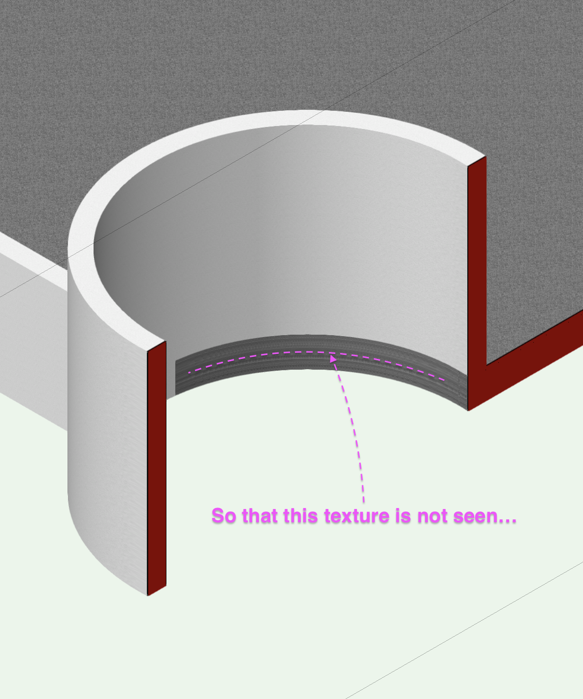
That works fine @Alan Woodwellbut don't you get a green part of your slab projecting in the inner side of your curved wall? Is there a way to not allow the green colour of your slab to be seen in the inner side of the curved wall? Without having to create a component for the curved wall...
-
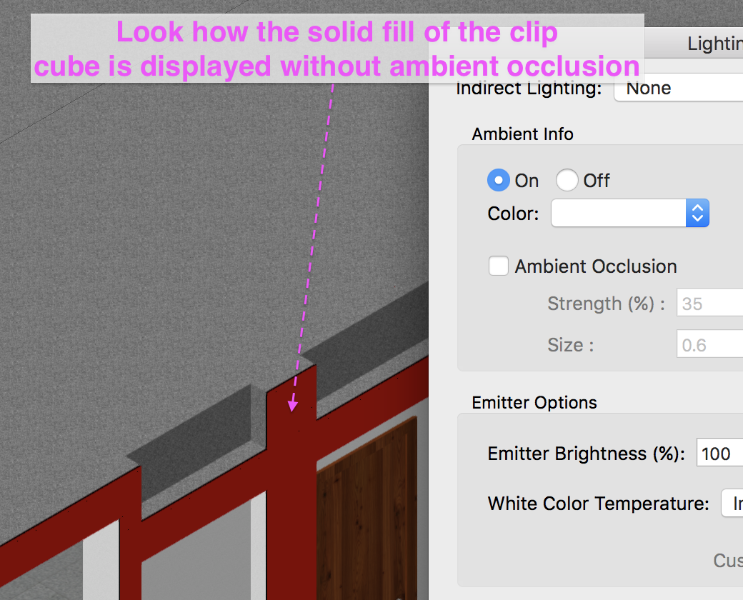
Hi,
I think this is a bug. It relates to how the Fill of the Clip Cube is visualized with and without ambient occlusion. Look at the two screenshots to understand the problem quickly.

-
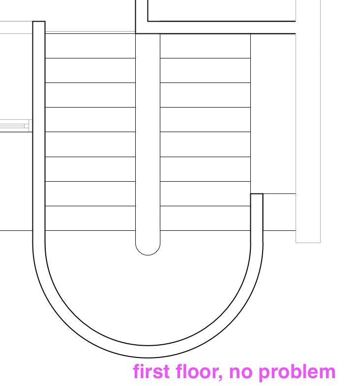
It would be nice that when one uses Fit Walls to Objects beneath a staircase the wall properly follows the bottom of the staircase. The only way to model this properly is to create a wall recess or wall projection.
You can see better what I mean in the screenshot. The wall "fits" with it's center but the top of the wall does not fit parallel to the bottom of the staircase.
.png.b326097b57a2c7a961bd971df627a62f.png)
-
 3
3
-
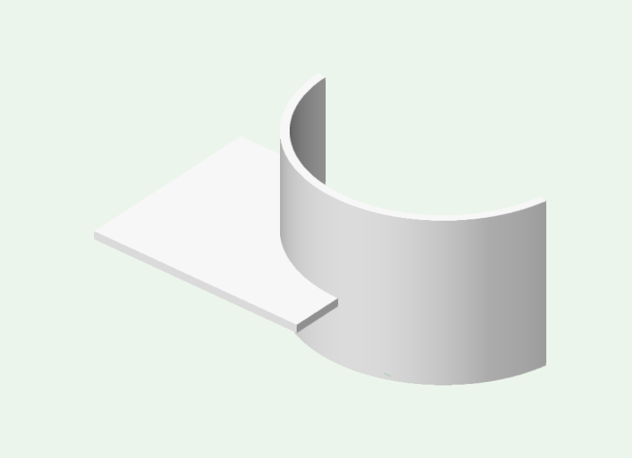
-
Managed to do it in the end... I used the Wall End Cap tool and added a circular polygon.
-
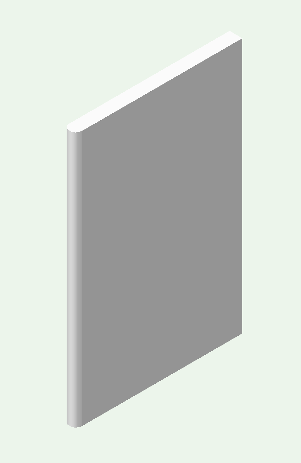
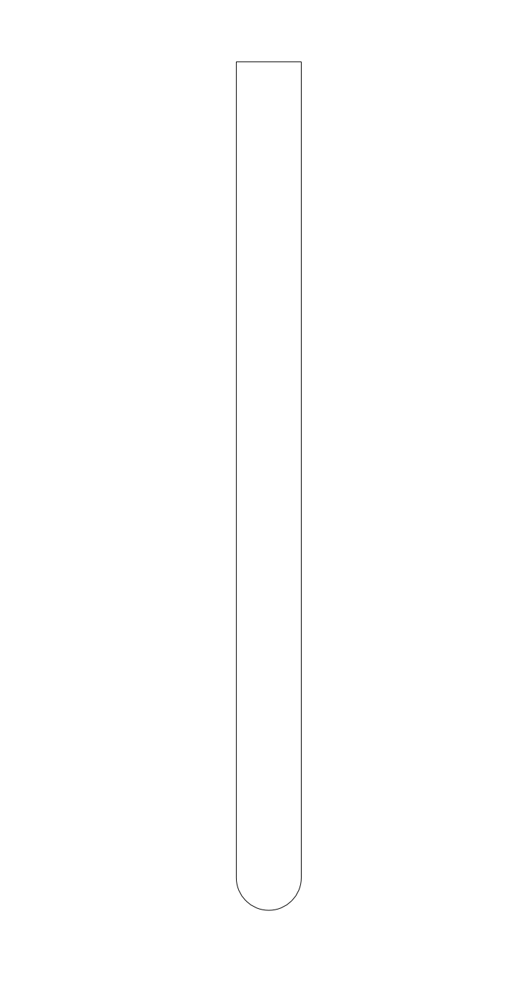
Hi,
can someone please explain me how can create a wall that has an ending which is round. I attach two images. One of the wall I would want to create in plan and in a 3D view (these have been created with an extrude, not with the wall tool).
I've fiddled with AEC > Create Wall Projection but I think you can only add stuff only to the sides of the walls and not the ends.
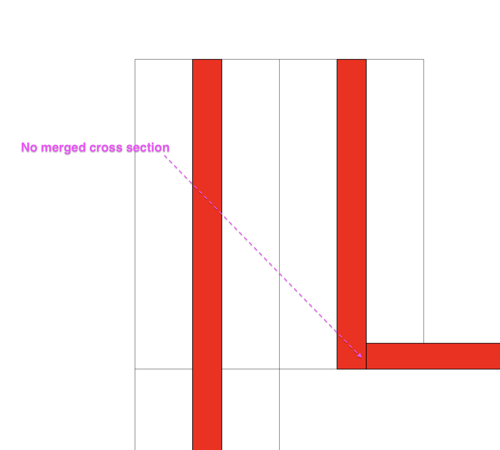
-
Many thanks @Alan Woodwell ! That fixed my problem. Now the only problem I still have (but I think it's just how the program works) is that even though I have Merged Cross Sections, the Curved wall and Curved Slab are divided by a line. As you can see in my screenshot.
-
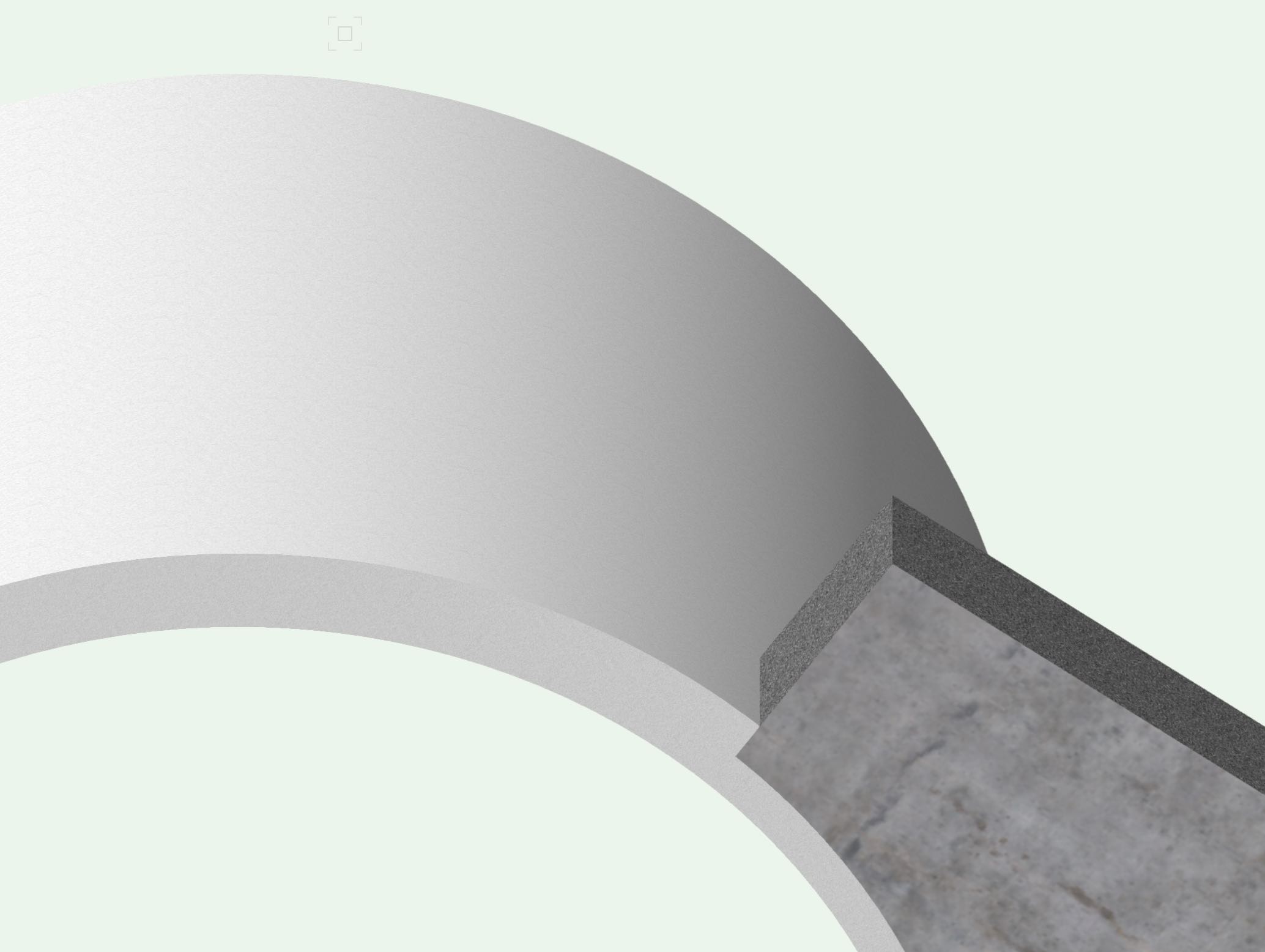
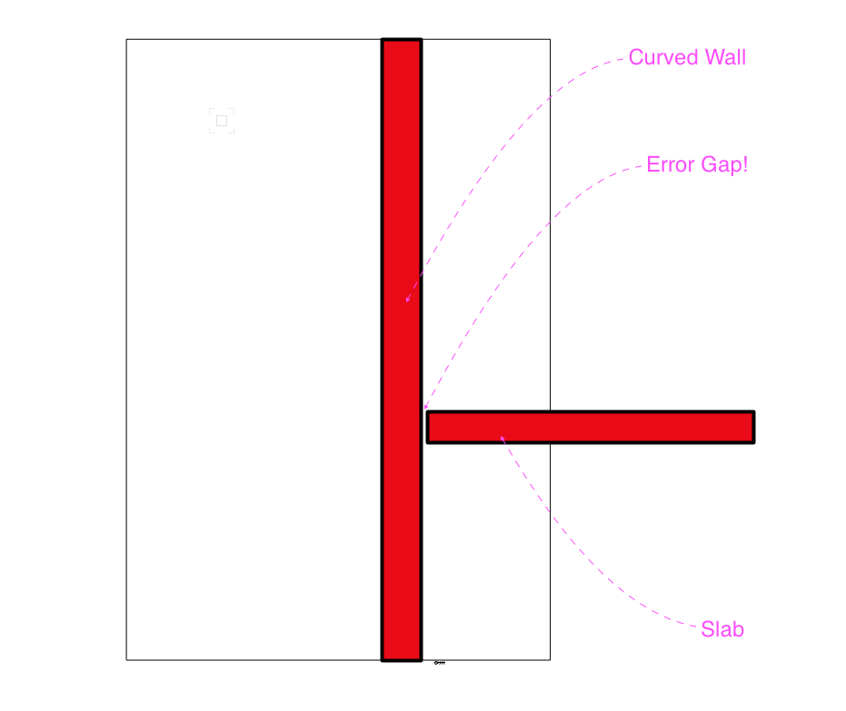
Hi, I think this is a bug.
A Section Viewport cutting through a Curved Wall and a Slab (with a curved part) does not display the section properly. There is a gap between the Slab and the Curved Wall.
I attach three images. One of the the model, the top/plan view, and another one of the Section Viewport.

-
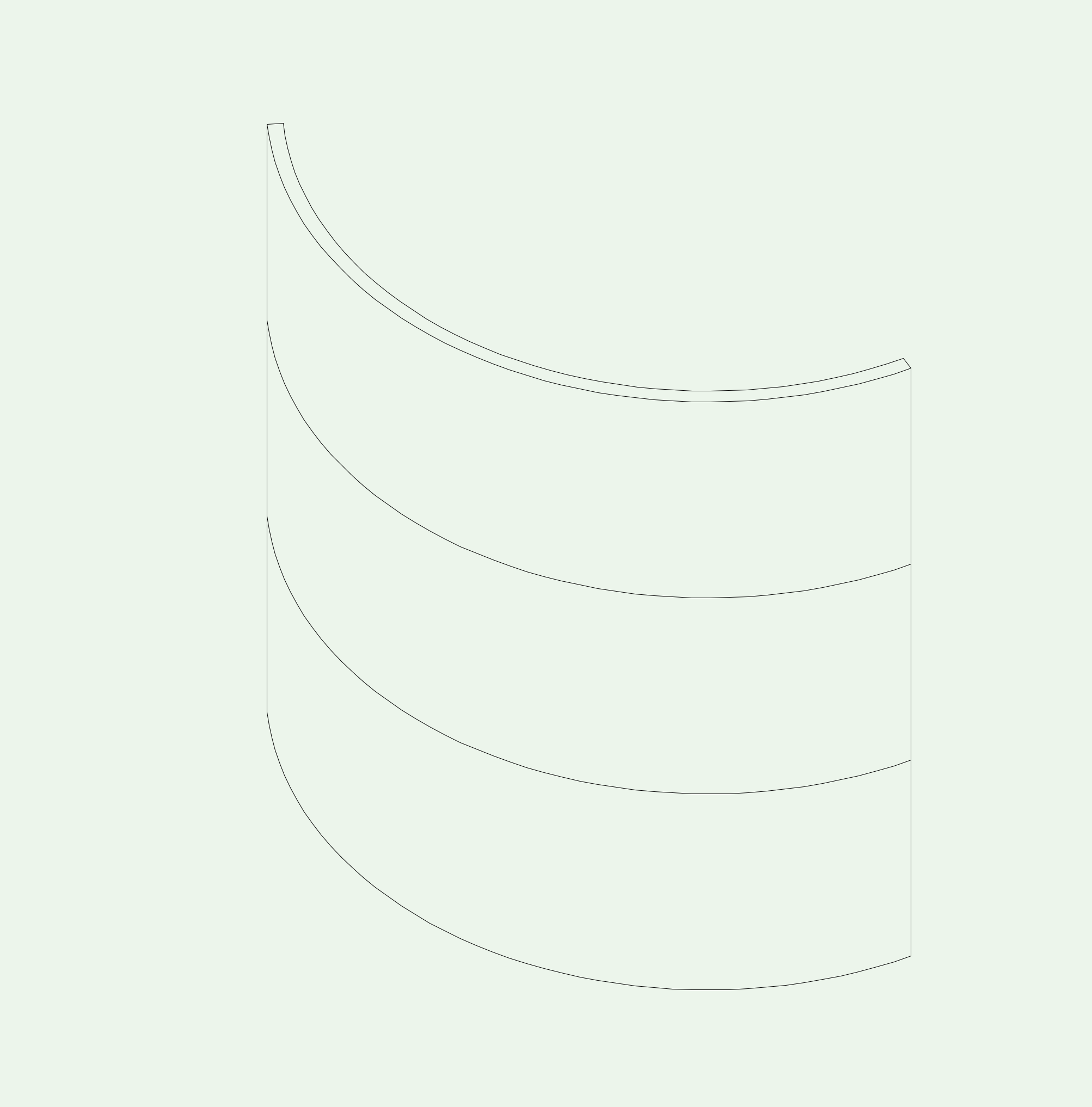
Hi,
I'd like to know if this is not possible or if I'm doing something wrong.
I've drawn three identical curved walls and placed them one on top of the other. Why do the horizontal lines show up? Shouldn't it be all like one big curved wall?
I hope I'm doing something wrong!
-
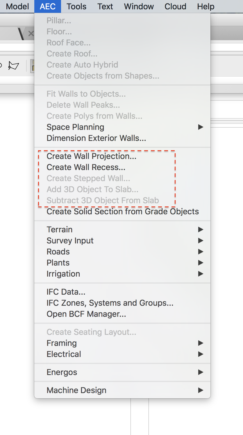
I solved my issue. I was actually doing a mistake. The appropriate way to subtract or add something from or to a slab or wall is using the different AEC commands:
- Create Wall Projection
- Create Wall Recess
- Add 3D Object from Slab
- Subtract 3D Object From Slab
When one does it this way then there is no problem with the Create Structural and Non Structural Groups options in a Section Viewport.
-
Hi,
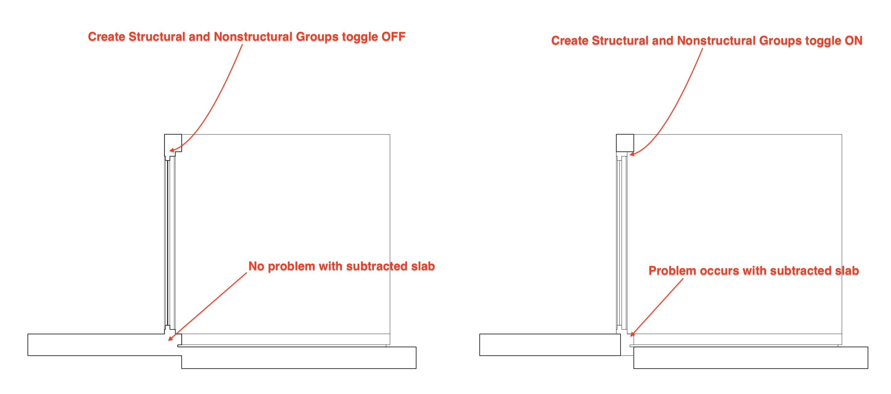
I think there is a bug when making a Section Viewport through a Slab with has been subtracted by an extrude and then viewing the section with Create Structural and Non Structural Groups toggled on.
Vectorworks doesn't recognize it's a subtracted slab and it separates it from the rest of the slabs surrounding it.
I attach a screenshot of the model and a screenshot of two section viewports.
-
Thanks a billion times@Alan Woodwell!!! I followed your steps and it worked.
-
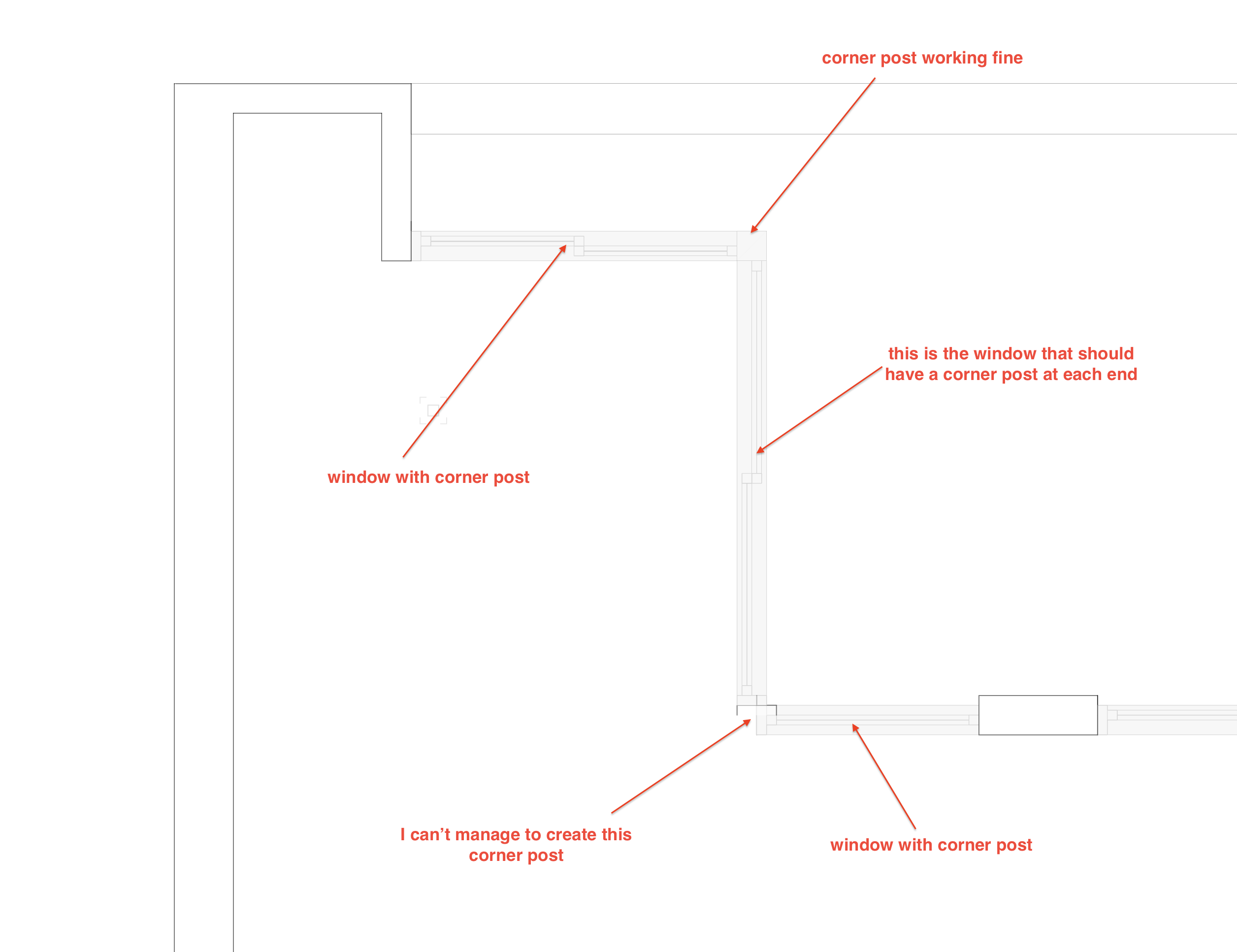
Hi,
I want to create a window that has two corner posts. In other words one corner post at both ends of the window. I don't know how to do this. Can someone please explain me.
I attach an image that explains better what I'm trying to do.
-
Thanks @Alan Woodwell but that's exactly what I did in the uppermost screenshot.
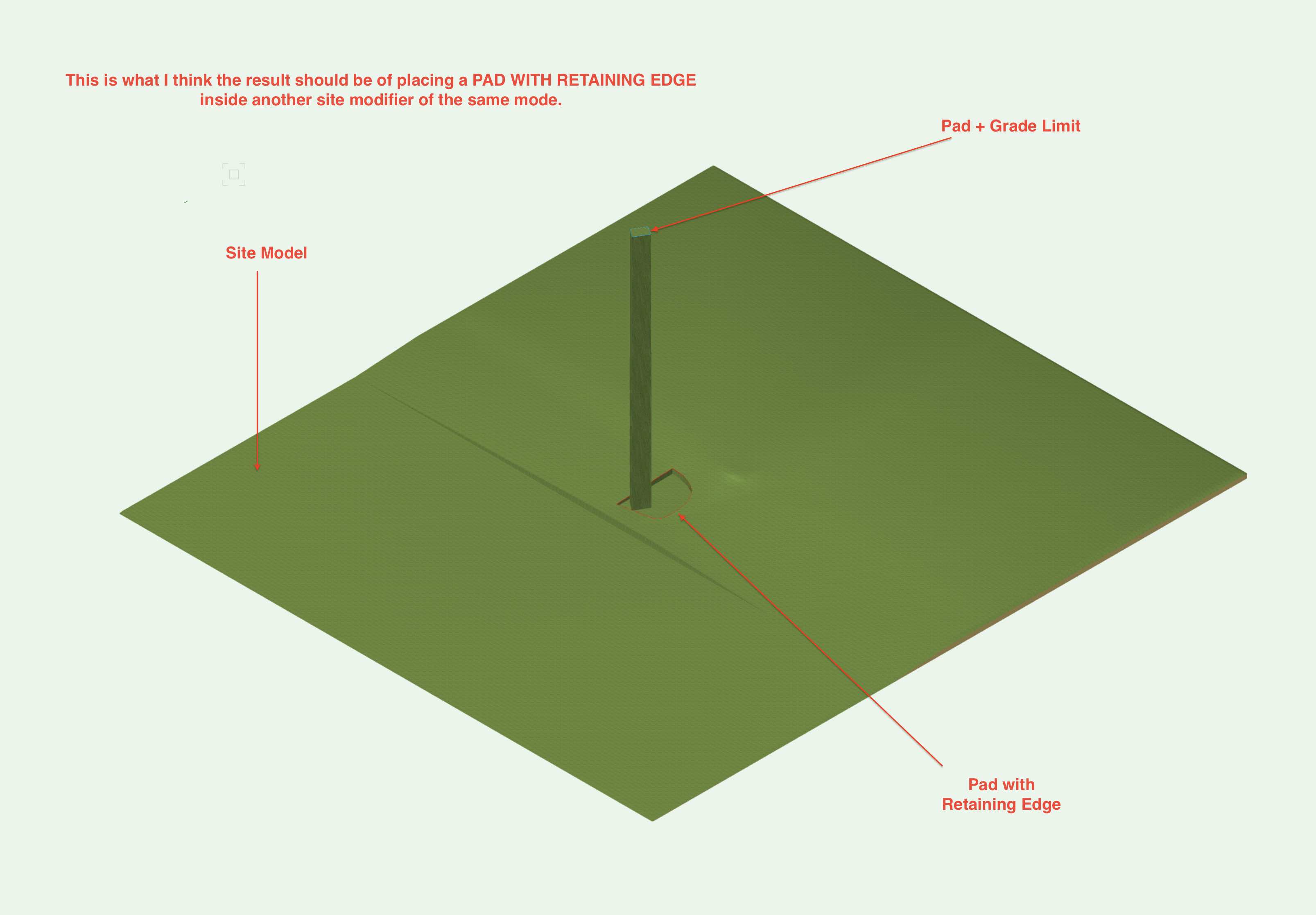
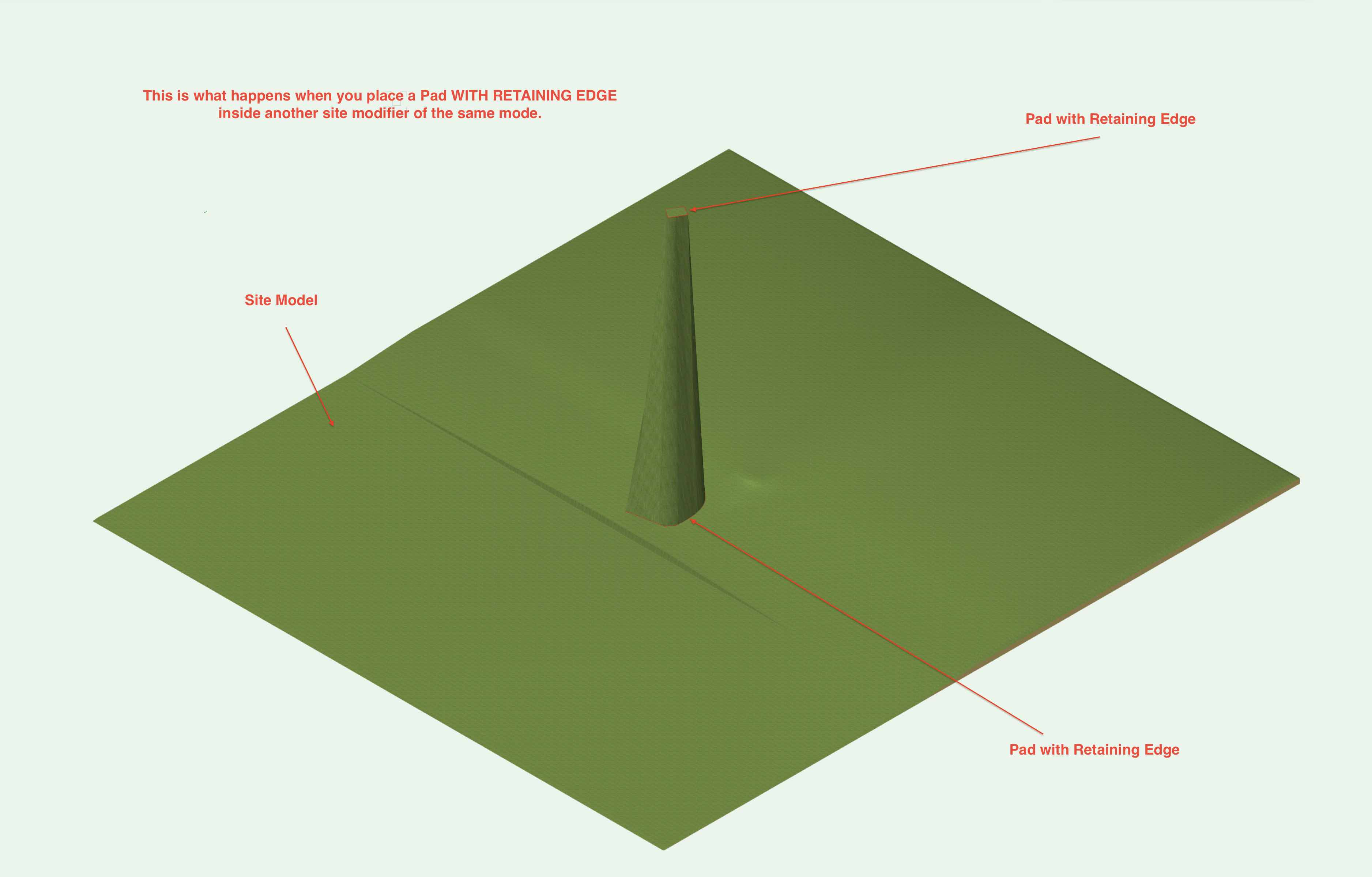
What I'm wondering is why doesn't a Pad with Retaining Edge inside another Pad with Retaining Edge have a straight edge. I suppose it would be logical that it would have a straight edge...
-
Hi,
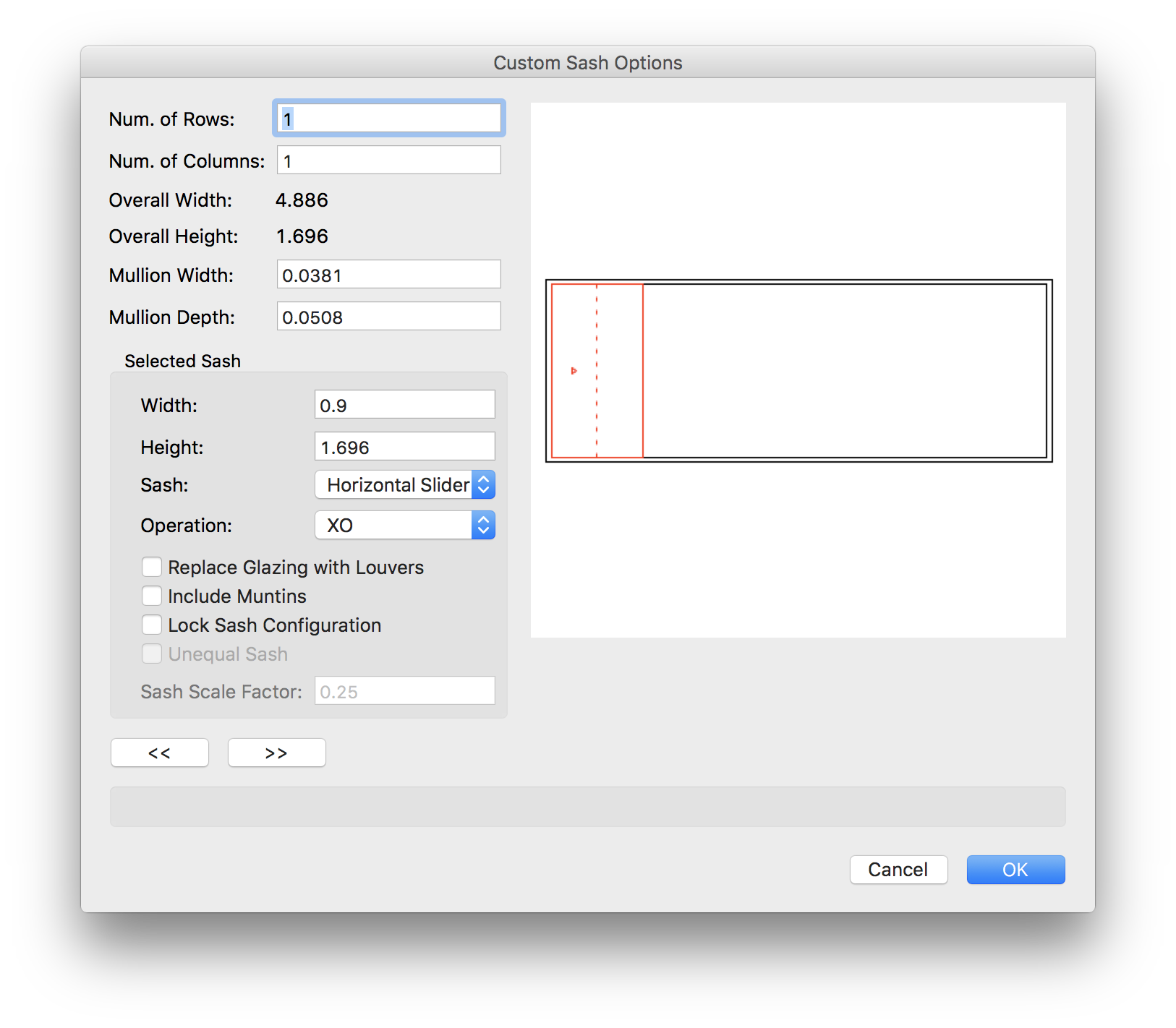
I think it would be amazing if Vectorworks would let us create a window that has a shorter sliding window over a larger window. This is a very common type of case... But currently there is now way of creating this parametrically.
I attach two images.
Number 1 is the closest we can get to using the window tool in Vectorworks.
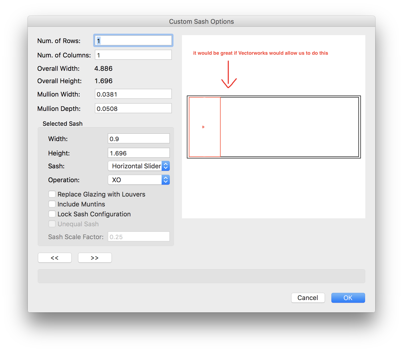
Image 2 is the type of window I wish Vectorworks could be capable of making parametrically (photoshopped image).
Hope it gets implemented soon!
p.s. If this could be implemented to the door tool that would be even better!
-
Hi,
I'm having trouble getting a Pad with Retaining Edge to Work inside another Pad with Retaining Edge. I attach two screenshots. One is of a Pad with Retaining Edge inside another Pad With Retaining Edge and the other one is the way I believe the combination of the last two mentioned should work (the second screenshot is made though by a Pad with Retaining Edge containing a Pad with a Grade Limits)
Am I doing something wrong by placing a Pad with Retaining Edge inside another site modifier of the same mode?
-
ok. Thanks. Will do.
-
The same thing happens. Actually, the quality slider is greyed out when I try to export to PNG or TIFF (but it's greyed out on high quality). It is greyed out through Export Image and Publish.
It is not greyed out when exporting to JPG.
Wall Recess Edge Issue
in Troubleshooting
Posted
Yes I would love that my stair would be cut as my slabs. But from what I see it seems stairs still don't cut as slabs.