


stayathomedad
-
Posts
59 -
Joined
-
Last visited
Content Type
Profiles
Forums
Events
Articles
Marionette
Store
Everything posted by stayathomedad
-
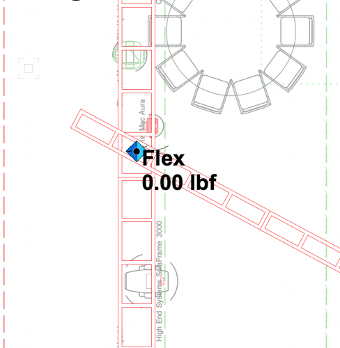
 Good day Braceworks Puzzle Solvers™ I have a file that has my rigging objects in it and I am referencing the audio, lighting, scenic and video objects through a design layer referenced viewport. The process works great and when I run a calculation it generates an error that shows the (6) lighting instruments upstage of the truss as not attached. This is as expected, since they are not in the footprint or at the height of the truss. I then add (6) lighting pipes and attach them to the truss on top. Now when I run the load calculations I get the following errors. There is a lot of this that confuses me: What causes the "Virtual FEM support gets load" error? Why do those (6) lighting fixtures that were shown as not being connected before the lighting pipes are now showing an error that they are assigned to two structural elements? And, craziest of all - Why do some lights that aren't even on that same truss system now show an error that they are also connected to two structural elements? (Seen on the left side of the screenshot) The only difference between these two drawings is the addition of the lighting pipes. Any input into what is happening would be awesome.

-
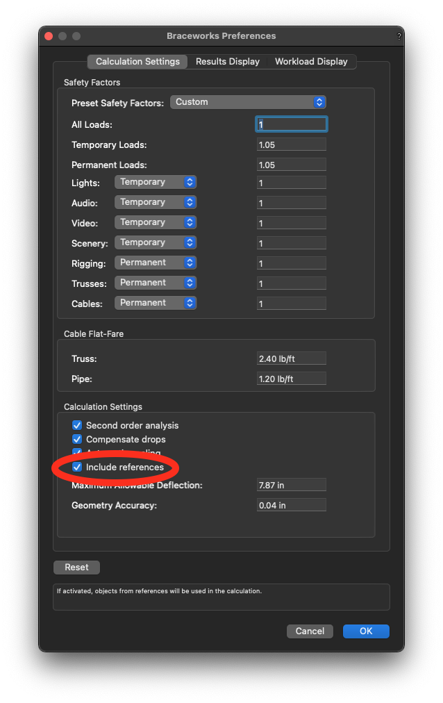
Interesting. I have been calculating referenced objects with Braceworks as I figure out my workflow to use Braceworks in combination with Project Sharing. This has allowed me to access loading data from other user's objects without having to check them out and take ownership. In the Braceworks preferences there is a checkbox to allow calculations from objects that are referenced in. This has been working perfectly fine with all objects so far. I have been able to "attach" lights, drape, screens, projectors and even custom built scenic objects with loads to my truss. The weights of all of these objects get picked up as part of the truss system based on being close to the same heights. I am trying to get my head wrapped around this a bit better so I can understand exactly when and why the referenced objects becomes associated with the truss but what I know now is that if they are close they get associated. This process breaks down with arrays. If I have two hoists and I get them close to the hanging position of the arrays they do not register the array load. But if I hang a stick of truss between two points and get that truss close to the hanging position of the array, the truss will include the array as part of the system. This can be seen when the system trim height is changed and you can see the red highlights around the referenced object. The obvious workaround is to simply not include the arrays in the load calcs and then add in point loads, but if someone has gone to all the work to have it function by attaching referenced loads to trusses that it wouldn't be to much to get it to work with objects that attach directly to the hoists.
-
UPDATE: It must have something to do with the zero values in one of the Records. Instead of zeros, I entered 0.01 or 1 and the Dead Hang symbols no longer lock up VW. Now I'm wondering which zero value is making this happen but I don't have enough time to sort that out.
-
Hello fellow Braceworks Puzzle Solvers™ Maybe I am doing something wrong, but it seems pretty straightforward to me. The attached file "Underhung Hoists" works with Braceworks perfectly fine. The other attached file "Underhung Dead Hangs" is exactly the same content except that rather than suspending the lower truss from three ¼ ton hoists I changed the symbol to one of the Dead Hangs. I will be suspending the lower truss 5ft below the top one with wire rope stingers and I thought that this is what a dead hang would model. When I run a calculation on this setup is locks up VW and I have to force it to quit. Any ideas what is going on? My work around is to take the ¼ hoist symbol and eliminate the weight and geometry of the hoist. I fully expect that to work - But isn't that really the only difference between Dead Hangs and Hoists? In the OIP the Dead Hang is listed as a Hoist object. Any input would be appreciated. Underhung Dead Hangs.vwx Underhung Hoists.vwx
-
Same issue for me. Two hoists works as expected. Even with a hanging angle of 0° on the bumper It is not working properly. I see this behavior if I open up a new file, not just an existing one. This is the first hurdle I need to cross. Once I get the array to connect properly to a single hoist, I then have to figure out how to get it to happen through a referenced viewport. Any tips on that process would also be appreciated. Harry
-
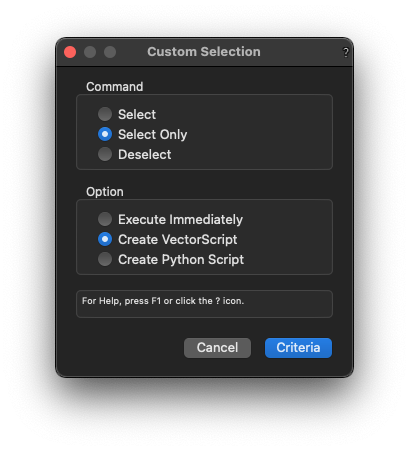
Try this: DSelectAll; SelectObj(INSYMBOL & INVIEWPORT & (PON='BrxCustomTrussCross')); SetClassN(FSActLayer, 'Truss Cross Turds', True); Use whatever name you want for the class, but I still like Truss Cross Turds. Symo, I too know very little about scripting, but started learning by using the custom selection tool to create a VectorScript. I then found and edited that newly created script inside the newly created script folder that was in the Resource Manager. My experience so far has been that once I committed to understanding scripting better, it was pretty easy to get answers from the VW Help portal and these forums. Mickey, I said those same things about Braceworks in the past but have been spending a good chunk of time getting it to work for what I do. I'm coming around to almost liking it. The bottom line is that it is a tool that will be used in our industry and whether a production rigger like myself uses it or not, there is a need to understand how it works. When a person runs into someone that is using BW but only half way understands it and is making decisions on bad data, it will be very valuable to understand how to use BW properly.
-
Edit Criteria for Multiple Worksheets
stayathomedad replied to stayathomedad's topic in General Discussion
Thanks for the tip! It will save some of the clicking for sure. -
So I built a worksheet and then made multiple copies of that worksheet. Looking back, I wish I would have added more criteria than I did. Is there a way to edit multiple worksheets criteria as a group? Similar to the way multiple class attribute settings can be edited by simply selecting multiple classes and the "edit". I really don't want to edit all 30 of them individually.
-
-
I was told a couple years ago that there isn't a way to turn them off, as it is part of the Braceworks module. I think that it is still true, but I haven't dug into it for a while. My solution is to create a class that is always hidden and every so often run my script to select them and then re-class them. The name of my hidden class is "Truss Cross Turds".
-
Looks like I am headed to the Hoist(Legacy) tool. I even tried to attach a custom record to the hoist symbols as jcogdell suggested, but when the hoist is inserted using the new Hoist tool, it seems to make the attached record fields inaccessible too edit.
-
Yes. It is called a Truss Cross in the OIP. It is classed into the active class. They are added automatically when two separate trusses cross each other's path.
-
I am referring to the automatically inserted Truss Crosses (see the attached screenshot). They are automatically generated and seem to get placed in the active class. For me, Braceworks is an add on that I have in case a client insists on using it. This happens for me maybe once or twice a year. I have my own load calculation process and I am leaning towards uninstalling Braceworks completely. There are too many limitations in the plug-in to work for me.
-
Is there some way for us to turn off Braceworks or at a minimum the component that auto adds the truss crosses? I use Braceworks only when I have a client that uses it also. 90% of the time I do not use it and I find myself constantly selecting truss crosses and deleting them.
-
FYI - I just checked SP2 and this does not seem to be fixed.
-
Yes, I have 2020 SP1 and that is where I am seeing this issue.
-
Thanks. Don't forget to mention that the whole process locks up as soon as you uncheck the 'Relative X,Y On Plot:' With that box unchecked the X & Y dimensions NEVER change.
-
Hoist Dimensions can NOT change units in VW 2020
stayathomedad replied to stayathomedad's question in Troubleshooting
This discussion has continued here: -
Also, if you add those 'Measure From:' X and Y distances to the Hoist Data Display and have the 'Relative X,Y on Plot' check box checked you would expect to see the values of those X & Y dimensions to be the same. It ends up that the X & Y dimensions added to the Hoist Data Display actually display the previous measurement when you move the hoist around.

-
Yes, I understand that. 1. Place a hoist anywhere in a drawing and have the 'Relative X,Y on Plot' check box checked and turned on. 2. Move the hoist and the 'Measure From:' X & Y dimensions behave as expected. 3. Uncheck the 'Relative X,Y on Plot' check box. 4. Move the hoist and the X & Y dimensions do NOT update. If you go through those simple steps you will see what I'm talking about.
-
It gets really weird if you add the "X" and "Y" Hoist Fields to the Hoist Data Display while having Relative X,Y turned on. Those numbers should be the same, but they aren't. There is definitely something off with this tool and these numbers.
-
Hoist Dimensions can NOT change units in VW 2020
stayathomedad replied to stayathomedad's question in Troubleshooting
This is interesting. I checked again to see if I can reproduce the error. It seems that one must keep the box "Relative X, Y On Plot:" checked in order for the Relative X,Y to be recalculated. If that box is not checked, the "Measure From:" numbers do not change. Since I don't use the Relative X,Y on Plot and all of my worksheets reference the Measure From value this still is causing me problems, but I now see the workaround. Thanks for answering my post. -
This is interesting. I checked again to see if I can reproduce the error. It seems that one must keep the box "Relative X, Y On Plot:" checked in order for the Relative X,Y to be recalculated. If that box is not checked, the "Measure From:" numbers do not change. Since I don't use the Relative X,Y on Plot and all of my worksheets reference the Measure From value this still is causing me problems, but I now see the workaround. Thanks for answering my post.
-
I noticed this also. Here is a thread I started in the Troubleshooting Section. If you are willing to, please like and flag my post so that we can get this issue addressed.
-
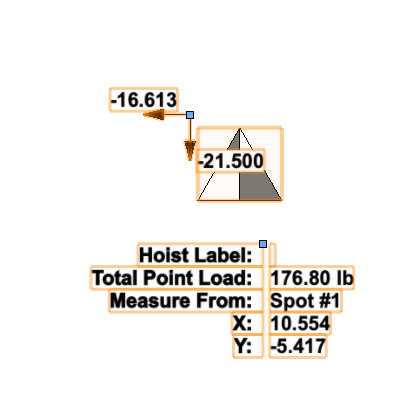
When a hoist is inserted into a document the "Measure From:" X & Y dimensions are locked into the units that were active when the hoist is placed in the drawing. If the units are changed for the document all of the other dimensions or settings in the Hoist OIP change as expected, but the X & Y in the "Measure From:" section stays unchanged. Refreshing the hoist does not solve the problem. I have played around with this enough to know that it is definitely a problem that needs VWs attention. I guess I will wait until the next service pack as this greatly affects my workflow. UPDATE: It seems that those dimensions aren't even updating when the hoist is moved from its insertion point. This seems to be a major issue within the hoist plug-in that may render the use of the Hoist Origin useless if you move or adjust anything.
- 3 replies
-
- 2
-

-
- hoist tools
- hoist
- (and 1 more)


until