


Boh
-
Posts
1,704 -
Joined
-
Last visited
Content Type
Profiles
Forums
Events
Articles
Marionette
Store
Posts posted by Boh
-
-
I second this! happens to me too.
-
 1
1
-
-
I haven’t done it for a while but pretty sure it works on vw2018. I haven’t come across the clipboard corruption chaos so far...
-
You could try grouping the viewport, copying & pasting into another file then using the eye dropper.
Edit. Ahh I see you already tried that.
-
4 hours ago, Kohli said:
Are you aware of any other script which allows me to rename multiple classes instead of ALL classes?
Sorry no. There is a class mapping feature which lets you map the classes of regularly imported classes. Though I have never used that feature.
-
Well, even though I have the Edit Class Names command, I still regularly use this script created by @Matt Panzer in 1997!
It simply adds a prefix to all classes in a file. Typical scenario is when I import dwg I do so into a blank file that has this script, run the script adding a "z-" prefix to all classes. Maybe clean out the dwg a bit more before importing it into my project file. All the random dwg classes will be nicely collapsed away at the bottom of my class list.
{ Written by: Matthew G. Panzer PanzerCAD Services, Inc. 1997 } PROCEDURE ChangeClassNames; VAR Count: INTEGER; ClassName: STRING; PrefixStr: STRING; BEGIN PrefixStr := StrDialog('Add prefix(to all classes):', 'DWG-'); IF (ClassNum>1) AND YNDialog('This will rename all of your classes! Are you sure you wish to continue?') THEN BEGIN FOR Count := 3 TO ClassNum DO BEGIN RenameClass( ClassList(Count), ConCat(PrefixStr, ClassList(Count)) ); END; END; END; RUN(ChangeClassNames); -
Can you add it to your workspace? If not it may be a local version plugin.
-
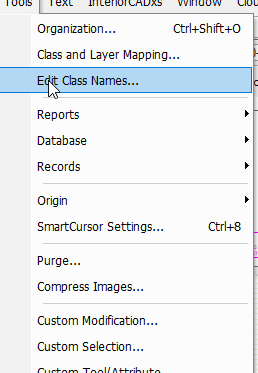
You can edit the names of mulitple classes at once via the "Edit Class Names..." command:
-
1
-
-
I suspect it may be part of the Australasian version of VW
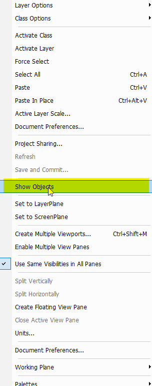
Try bringing in that “Custom Visibility...” command instead that @Pat Stanford mentioned. I played around with it but couldn’t figure out how to get a “show “ command that didn’t show objects on classes set to invisible.
-
Have you tried adding it to your workspace?
-
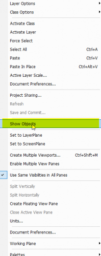
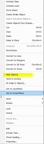
Hmmm Matt does the right click “Hide Objects” command as mentioned above not do what you want?
-
Hi @Phileas.
I was pretty much in the same place as you a couple of years back re working in an office where no one did anything consistently or in a standard way. This forum really helped sort it out. Particularly this thread with contributions from some real experts incl. @Jonathan Pickup One post by @Art V on October 15, 2017 was particularly helpful.
-
1
-
-
Wow I like that!
One thing though. I notice that creating a "Show all" script shows all objects but doesn't change their classes to visible. I.e. even objects on invisible classes are visible - which could get confusing.
I've noticed some right click menu items called "Hide Objects" & "Show All". "Hide objects" in the context menu hides all items which aren't selected, "Show Objects", available when nothing is selected shows everything except items that have their classes off.
-
There maybe as many classing systems as there are VW users but there are some standard systems that I think some people use.
We are small to medium sized architecture practice and have developed a custom system that we use in our office. We try to have as much as possible in our drawings defined “by class” so that changing a visibility, a hatch, texture or line weight etc can be done globally simply by changing or editing a class. This works really well though it does mean a lot of classes which, yes, do require some managing!
Our drawing set up typically is to 3D model the building on design layers and have as much 2d info as poss placed on VP annotations or directly on sheet layers.
Generally the only 2d info we put on design layers is stuff that needs to be seen in multiple viewports (e.g room labels) or stuff that needs to be seen in 2d under some objects and over others. E.g a polygon representing a carpet finish needs to sit on top of a slab but under furniture.
For almost all of the 3D stuff we have a range of classes with a “MODEL-“ prefix. This covers off 3D objects that form part of the model located on design layers. Most things will have their own classes based on what it is, where it is, and/or what it is made from. E.g.
MODEL-WALL-Framed_Exterior_New or
MODEL-WALL-Concrete_Block._Extg
For fittings we have something like
MODEL-FITTINGS-Fixed_ General,
MODEL-FITTINGS-Furniture_Loose
MODEL-FITTINGS-Sanitary Fixtures. Etc
Note the use of hyphens so the class hierarchy which can be collapsed or expanded in the class list, along with CAPS for emphasis of major categories. Also what I call “backwards” naming so that similar objects group alphabetically next to each other.
Note also we have avoided using numerical codes for classes as no single classification system really seemed to cover everything off in an intuitive way, (plus of course no need to remember numbers).
Plugin objects will have their own component classes. Where possible we have these in classes like: MODEL-COMPONENT-WALL_Framing or MODEL-COMPONENT-ROOF-Cladding_Metal etc.
We have a collection of wall, slab, and roof styles which use these component classes.
We have seperated site items into their own set of “SITE-“ classes so the site plans and site works items can be dealt with as a seperate thing.
Similarly we have a set of “DEMO-“ classes for existing items being removed. These don’t generally need 3D representatation hence they are not in a “MODEL-“ class.
Of course their is more involved. Other class categories include:
”TEXT-“, “DETAILS-“, ”ELEVATIONS-“ & “SECTIONS-“ for 2d objects and annotations.
“FINISHES-“ for 2d polys with hatches/coloured fills etc for floor and roof plans.
”SERVICES-“
”LIGHTS-“ for light sources used for 3D renders
etc etc etc
Inevitably there are some grey areas about how some things should be classed but I think our system covers off 95% of stuff in an intuitive sort of way.
We develope more classes as we go. Most jobs don’t need all the classes so our drawing templates just have a collection of commonly used ones for that type of project. We have a library file from which we can import classes if we need extra ones.
Another thing we have found is that naming viewports is really useful so that class visibilities can be globally edited in the organisation dialogue by viewport name.
VW 2019 has introduced class and layer filters which I think will be really useful. However we are still on vw2018.
i guess the system you use should complement the type of work you do and how you like to do it.
I hope that is helpful or at least interesting. Im keen to hear what systems others use.
cheers.
-
1
-
-
Do you have “full wall breaks” selected in the symbol options
-
In hidden line solid fills are white. If the objects have a render texture and the texture has a hatch associated with it then you can set the hidden line VP to show the hatches on those objects.
You coukd try opengl render which which will show objects with either a solid fills or a render texture.
-
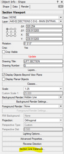
Note that these are two different objects:
One is a "Section - Elevation Marker" the other is a "Section Line". I'm not really using 2019 but in 2018 a Section Line is directly linked to a section viewport and is typically created via the "Section Lines..." option at the bottom of the OIP when a Section VP is selected.
I haven't tried it in 2019 but when I ungroup a Section Line in 2018 it changes to a Section-Elevation Marker which you can then link to a viewport.
i just posted a response to a related question here:
-
2
-
-
Not sure I follow...
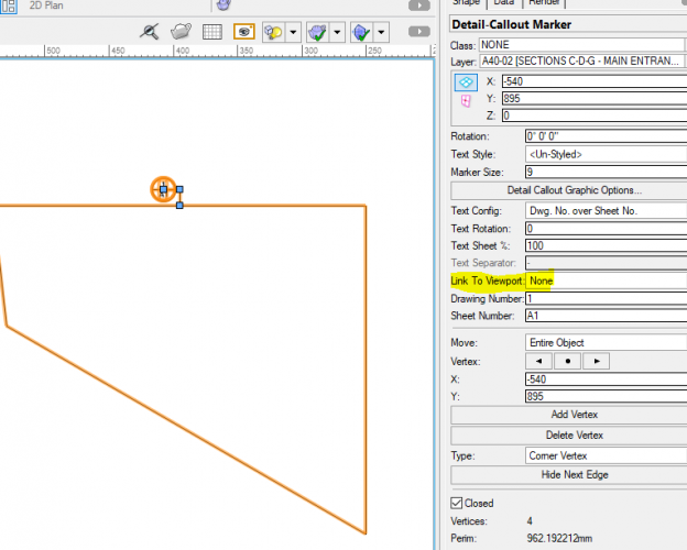
Detail & Section viewports can be linked straight to detail callouts/section lines. (Select a Section or Detail VP and at the bottom of the OIP there is a "Section Line" or "Detail Callout" instances button).
Other types of viewports can be linked using the Section-Elevation Marker tool, or the Detail-Callout Marker tool. In this case you place a section marker and in the OIP decide which viewport to link it to.
-
2
-
-
7 minutes ago, cberg said:
That said, you can also extract the detail from the annotation viewport and put them into a 2d design layer of some sort so that they can be reused from project to project
If you want to be able to reuse details in other/future projects then the details in the annotation VP can simply be turned into a symbol definition and placed in your library. From there they can be imported into other project files..
Note the detail VP itself can't be made into a symbol but the annotation info in it can. As mentioned before you can copy & paste VP's from one file to another - you just need to group them first.
-
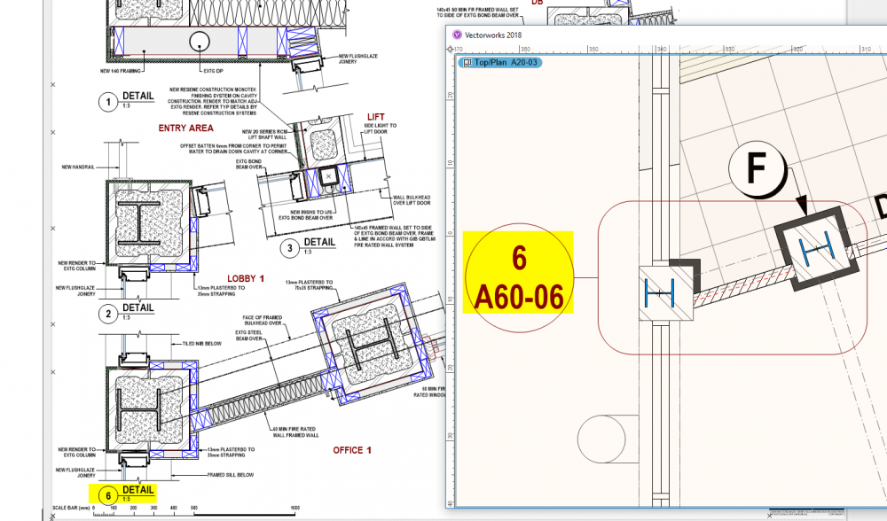
That's an interesting way to go which I think can work very well. I've have been experimenting with a slightly different way:
Since we generally create a 3d model all our elevations and sections are live section viewports. From these we create detail viewports on our sheet layers. The design layer info in the VP's is just used as a template over which, in the annotation space of the VP, we overdraw our 2d details (or possibly place a detail symbol) . Once the detail is completed the design layer's visibilities can usually just be turned completely off. So we end up with detail VP's with only annotation info in them.
The advantage of this is:
- No additional design layers are required for 2d details.
- Design layer scale is irrelevant - all text/page based info is scaled to the sheet layer (informed by the detail VP scale).
- Sheet formatting is simple, as all info is in the annotation space there is no tedious cropping of viewports and/or moving design layer info around to fit into a VP crop.
- Each detail has it's own viewport which can be moved around like a group to suit your sheet.
- Each detail viewports automatically update their number/sheet directly to the detail markers on the plans/sections.
Note that:
Details are typically only used in one viewport so why not put it into an annotation space? If repetitive detail info is required then this could be via a symbol definition.
Detail info is not generally required to export to dwg - so far we haven't had any issues there.
So far so good - the only downside I've come across so far is that live details still need updating before publish even when there is no DL info in them. Usually this is pretty quick though.
-
1
-
You won't be able to easily set up detail symbols with details drawn in a design layer but annotated in VP annotations. All the info really needs to be either on a single design layer or in the VP annotations - not a combination.
If they are all on a design layer you can then create symbols of each detail and file them in your library for later re-use.
You are correct that text formatting/page based info will need reformatting when the scale is changed. I have found however that 'generic' details are best set up for one scale and simply pasted into your drawing. They are at a certain scale because that best suits the info it represents. For example a window sill detail which shows all the weatherproofing info like seals and flashings etc needs to be at a small scale certainly no bigger than 1:5. So a suggestion may be for your office to standardize the scaling of your details so symbols can efficiently be inserted with no reformatting required.
There was a recent thread on this however where I came up with a workflow to use page based symbols for detail symbols so that text formatting can be retained and different scales. Hasn't been road tested yet tho...:
Re transferring viewports: You can't copy & paste a VP from one file to another but a neat trick to transfer those details to a different file is if you group the VP first you can then copy & paste it to another file.
-
2
-
-
2 hours ago, MTRobin said:
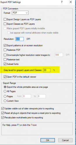
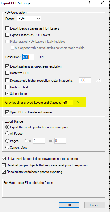
I have found that the grey option works in wireframe, but when you publish it to PDF it still prints as black.
Have you tried adjusting the setting to adjust the level of "grayness" when you publish?:
-
Ok. Thanks Matt, I appreciate your time looking at this. I'm glad this little issue is sorted on 2019. We are holding off using 2019 for now as it looks like it has too many other bugs and will effect our productivity.
Perhaps when the next service pack is issued we may start using it.
-
I notice the "snap to working plane" mode is activated as well as the object snap being deactivated. So it definitely seems to be a 3d issue.
Have you tried it in different plane options?
Is it file specific?
I though it might be this:
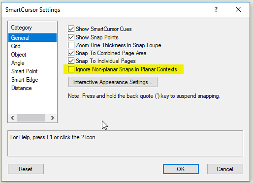
But I can't seem to reporduce your issue.
Sorry I can't offer any more suggestions...
-
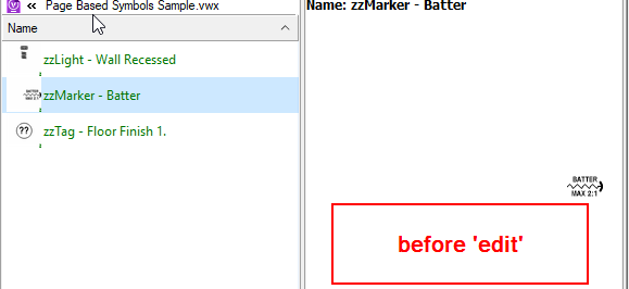
Hi Matt.
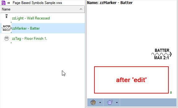
Here is a sample file with a couple of page based symbols. I've checked and the bounding box is no larger than the visible objects. It seems to happens on most of my page based symbols on both vw2018 & vw 2019. The odd ones whose thumbnails do look ok, if I 'edit' them the thumbnail will then change size, even though I haven't actually changed them -. just gone straight in and out of edit mode.
In the screen shot example below the thumbnail got bigger after 'editing'. Doesn't work for most of them unfortunately.
It will be interesting to see if any of this behavior happens on your machine or on a new file into which you have imported the symbols.
Thanks again for your help.


need help with Wall in a symbol
in Troubleshooting
Posted
I have had similar problems using walls in symbols. It seems the wall height reference gets lost in the symbol definition. I think this is because the definition has it's own z height reference.
I haven't found a consistent workaround using walls in symbols yet. I'd be interested to hear if someone knows a good way.
Could you try making design layer viewports of the garage instead?