LarryO
-
Posts
428 -
Joined
-
Last visited
Content Type
Profiles
Forums
Events
Articles
Marionette
Store
Everything posted by LarryO
-
VWX 2013 - slow graphics and crashing - memory leak
LarryO replied to rozeman architects's question in Troubleshooting
It is not generally the quantity of viewports but the complexity of what they are attempting to render. Then the quantity will multiply the memory use. -
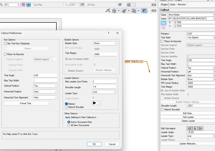
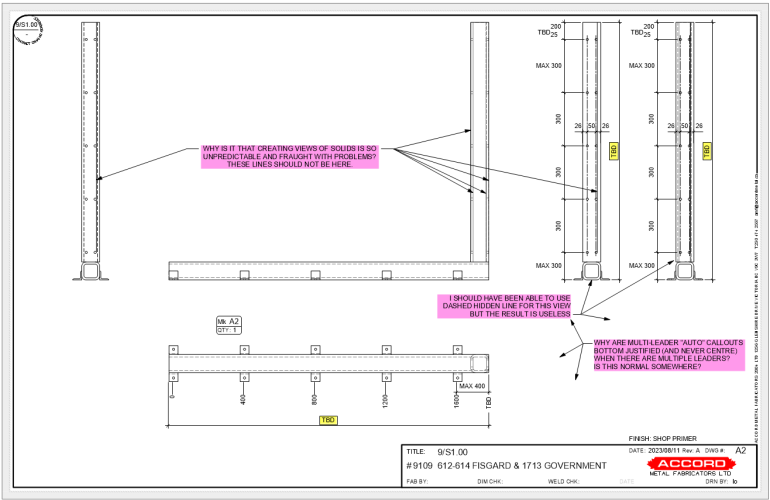
I am finding that when creating a new callout where the leader extends off to the right that the tool creates an instance where the Horizontal Position gets set to "Left" even though the preference was set to create them as "Auto". While this is not immediately an inconvenience, when one is flipping notes for symmetrical reuse it becomes a frustrating !surprise! This only seems to occur in 3 point mode, VW2023 & VW2024. Is this a bug or something I am missing?
-
VWX 2013 - slow graphics and crashing - memory leak
LarryO replied to rozeman architects's question in Troubleshooting
If you have a memory intensive object, or a few of them, (such as an imported pdf object rendered in a viewport, etc.) as you edit them the number of undo steps you are saving can increase memory usage quickly. But this should plateau as you get to the max step saved and only the system swapping memory blocks to disk should slow it after that. Saving and reverting to saved may help but you do lose the undo steps in the process. If that doesn't produce a reduction then is not this specific memory hog. Without context the issue(s) you are experiencing cannot really be diagnosed. -
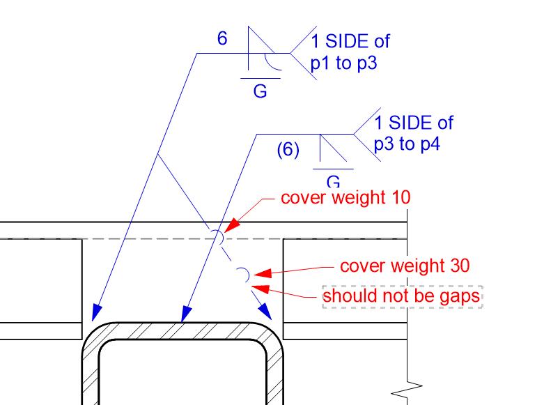
A mask seems to cover the original line but it extends both before and after the bridge segment and a cover weight of 1 doesn't mask the original line. The original line should be connecting to the bridge segment on each end of the bridge should it not?
-
When editing callouts, specifically addition and deletion of leaders, the functionality missing is the use of ALT to select another callout instance to continue editing. There is a behaviour continuity issue here when compared to other editing operations. One must stop the operation by pressing X before selection of another callout can occur and then reinitiate the operation (additions or deletions). An almost daily frustration.
-
I'm assuming the objects imported are contained within a symbol definition with an instance present on the layer that was create by the import. Here is a scenario to test to see if you are looking at the symbol's plane or the layer's plane when editing. Set the origin of an instance of the symbol to zero,zero,zero (x,y,z) in the IO palette. Set the view of the layer to top or top/plan. Choose to edit the symbol in place and if the symbol was defined on a plane other than the layer plane there will be arrows indicating the direction of the axis. And if you press zero on the keypad twice the view will rotate away from the layer's plan as it switches to the top/plan view of the symbol's defined plane. At which point you can press 2 to get the front view relative to the symbol's x-y plane. Now whether Move 3D Selection responds to the layer's plane or the symbol's plane will depend upon if one selects Cartesian or Working plane in "Move 3D Selection" dialog. At least that is how it generally responds when I use it.
-
Snapping stops working when editing deeply nested objects.
LarryO replied to Bruce Kieffer's question in Troubleshooting
The only reprieve I have had from this issue and it doesn't always work is to change to wire frame. It is like forcing an update in a viewport when trying to dimension in hidden mode and the snaps stop appearing. -
I noticed some unexpected behaviour today while flipping objects within a 3d symbol. VW2023 If I flipped 3d object(s), not grouped, they flipped about their collective middle/centre. If I flipped 2d rectangle(s) on a 3d plane they flipped about the symbol origin when flipped horizontally. The were placed on the x-y plane at z=0 and not grouped, but I don't think it mattered other than that they were not screen aligned. Finally if I flipped those same 3d objects and any one of the 2d rectangles, all of them flipped about the symbol's origin and not their collective middle/centre. Larry
-
Depending upon how you approached the rotation the objects may have already been on the z-axis of the x-y plane of the symbol and it was the symbol that had been rotated 90° in the drawing environment along either the x or y-axis which would have aligned the z-axis of the symbol's x-y plane onto either the y or x-axis respectively of the layer.
-
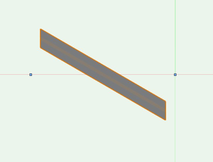
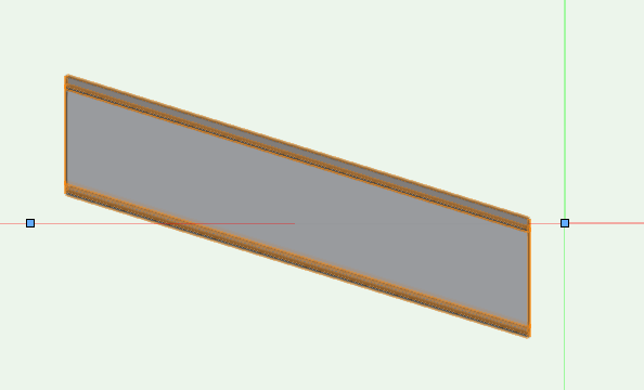
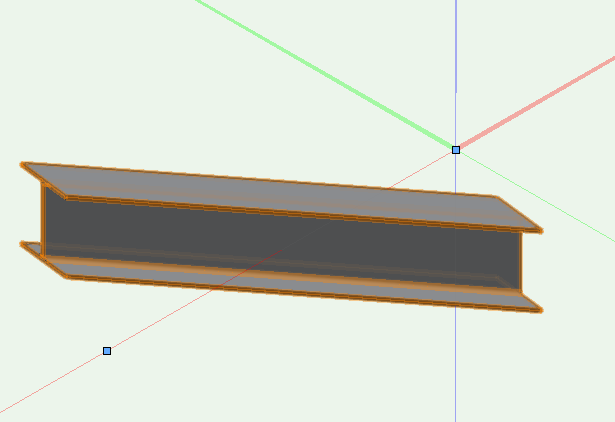
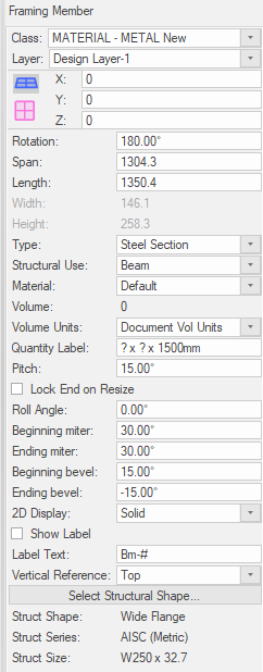
I have tried a couple of times to use this object/tool because it seems to have a lot of the capabilities one would want for creating and documenting a 3d framing system, but there always seems to be glitches that have yet to be addressed. Like this one in the image. I drew the beam from right to left in plan view before adding the pitch, bevels and miters. I then attempted to rotate it into position but one must first change the view to top/plan because it is recognized as a hybrid symbol and will not rotate in any other view. Then enter the rotation value in the dialog but the rendered view shows doesn't change so I rotate it back to the original orientation along the x-axis. The result is this image. One step behind my action; very frustrating. There doesn't seem to be a setting to keep the end points aligned to the visual object, particularly when there is an elevation change. For the x/y/z-values only the start point data can be reviewed in the object info. VW2024 Views are plan, front and iso in that order.
-
I wonder if this is a result of a change to an event handling or event generating routine, possibly at the system level. I noticed that while using VW2023 there are unpredictable crashes to desktop when clicking the layers button (not the pull-down but the primary layers submenu window). Also bringing up the symbol window when replacing a symbol the button within the dialog hesitates its response until you attempt to move the mouse away from the button, leaving you with an unstable feeling that the program is having a mini-stroke. There are two others I have noticed as well that cause the program to crash to desk top more frequently than past versions, and some of that might be a result of me investing more time into utilizing 3d objects so I wasn't exposed to glitches that could be a result of memory problems from 3d sub-routines. I've actually had those annoying improper call or missing (resource?) something or rather dialog pop up a few times this week. The one that repeats itself 10 times or so before either stopping or crashing.
-
This is VW2024 update 2 (just installed) first launch. Full screen. the shadow line occasionally is shows correctly (as seen in 2nd image), but as soon as VW is the active app it reverts to the image above. Intel(R) Xeon(R) W-2123 CPU @ 3.60GHz 3.60 GHz RAM: 16.0 GB (15.7 GB usable) Product ID: 00391-70000-00000-AA565 64-bit operating system, x64-based processor No pen or touch input is available for this display Windows 11 Pro for Workstations Version: 22H2 Date: 2023-04-14 Build: 22621.2715 Windows Feature Experience Pack 1000.22677.1000.0 <EDIT: why is this version, VW2024 using about 7x the RAM as VW2023 without there being an open file?>

-
Snap to 3d locus for dragging Viewport into position??
LarryO replied to LarryO's question in Troubleshooting
hmmm, this works sometimes but not all the time. Today VW got its cuppa caffeine; yesterday it was not very snappy. -
Should I be able to snap to a 3d locus when attempting to drag a viewport to a new location? What about a symbol's insertion point? Referring to objects in the VP's design layer not it's annotation environment. I know mid, end and a few others are normal grab points, but they are defined by an object like a line or extrusion and not objects in themselves.
-
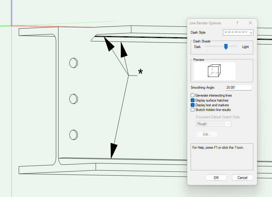
Why has it been so difficult to stop these lines from occurring? Over the years of VW development no repeatable technique nor application fix has emerged to ensure a predictable outcome for this problem. Aside from tedious masking techniques which require repeatedly scanning viewports after adjustments to 3d objects. This is a simple Wide Flange beam with subtract solids performed to create the round holes shown and remove a portion (cope) of the top flange. Doesn't matter if the subtraction extrudes have three circles or one or if all the subtractions are separate operations or conducted as a single one in this instance.
-
I'd attached the VW2023 file to the forum but it is 9.5MB. edit: Never mind, I sourced the problem. Two layers were showing and the historical layer didn't have the visibility class assigned to the two groupings but it was behind the current layer so I couldn't select the groups in question. Duh!
-
Hi Pat, It is actually the opposite that is the problem. My objects within the group are a mix of types (and potentially classes); symbols, extrudes, etc, but all 3d. So rather than create a symbol that had no other purpose than grouping them to assign a visibility class I grouped them. One group for the open gate and the other for the closed gate. But in a viewport rendered as shaded I cannot get either of the groups to be invisible when I make the class invisible. And interestingly when I go into edit layer mode from said viewport both groups are not selectable but are visible at approx 75% which is, surprise, then attribute of the class assigned to most of the objects within the group. When I make the parent group's class visible and select the object the attributes that appear are not the ones assigned to the class of the group but reflect those of the majority of the 3d objects within said group. Actually I think all of the objects in this current grouping are assign ed the same class, one i created to represent steel objects.
-
Thanks, fixed!
-
I created a steel framework for a floor pit with two hinged gate panels. Wanting to show one of the gates open in one view and closed in another. Are groups not an option for making objects invisible when rendering 3d objects in shaded mode? I'm referring to using classes and assigning the group an invisible class to make all the objects within disappear. One class being open gate and the other closed gate. I think I can answer how to achieve the end goal. Use a symbol instead of a group because the rendering engine recognizes when they have an invisible class assigned. Task: try this tomorrow.
-
It has been so long since I have needed to enter my password I've forgotten it. An upgrade to the OS and Chrome at home has effectively logged me out of the forum on my home computer. So at work where I am still logged into the forum I was going to put in a new password so I could log in again at home, BUT one needs to enter the old password to do so. Now I am stuck. Anyone know what my options are for getting logged in again at home when I cannot recall my password anymore?
-
Non-existent lines appearing on sheet layer viewports
LarryO replied to oliver.williams's question in Troubleshooting
jmcewen is on the right track for attempting workarounds. 1: Substitute a clipped polygon extrusion for an extrusion that has subtracted objects that are perpendicular to the work plane and visa versa sometimes works. 2. Sometimes not adding two solids that are touching or intersecting will produce the correct look without corruption. 3. Adjusting the length of a cutting solid in a manner that is not changing the desired recess or hole will sometimes remove the corruption. 4. Recreating and then replacing the original cutting object. With multi-object extrusions it is occasionally only one of the outlines that needs to be replaced, but in the file I uploaded in the other thread there are three circles in the extrusion out of five that if present cause my extraneous line to appear. -
Smoothing angle is at 5° but it doesn't matter if I set it at 20° or even 90° when viewing solids that are clipped in any fashion these unpredictable lines can appear. VW2023 9109 612-614 Fisgard.vwx
-
You write a Procedure which seeks out all instances of the plugin and assign it to a button in the OIP. The tricky part I suspect might be whether or not the values you just changed in the plugin instance have been transferred to the attached resource so that you can capture them to copy to all the other instances. The script compiler usually doesn't update the resources until the script finishes. Would pressing this "update" button cause the plugin instance's script to run a second time if a reset object was issued in the script? Sorry I don't think I have any relevant examples. <edit: I suppose you could use the Procedure in a tool and simply click on the plugin instance that you wish to transfer the values from to its other brethren. Just place script in the right mouse button menu if it is a frequent use item. >
-
While I don't know the cause, you did mention that you can copy the affected viewport to a clean sheet and it performs as expected. That is a reasonable approach if it is a corrupted sheet. But before trying to remove corruption from a file ensure you work with a copy of the file until you are satisfied with the result, then the original can be overwritten. Copy the problematic viewports first; confirm that they display correctly. Now copy in the reference viewports if they were on the same page. Create a new reference tag in the copied VPs using the button in the OIP. You will need to know the new reference VP name when doing so. If everything resolves itself you should be good at that point to delete the original VPs and the sheet. Rename the new sheet and good to go?? Sorry I cannot speak to moving title blocks as we use our own and not the VWs generated product. I hope that though process is of some minor help.
-
Invisible 3d object(s) appearing in VP sections. Glitch vw2023sp5?
LarryO posted a question in Troubleshooting
During the initial creation of a section VP solid 3d objects in a symbol will appear if sectioned even though they are in an invisible group inside the symbol definition. Symbol instance has visible class applied, objects within have visible class attributes (to define object appearance when visible; being sol) but some are in a group which is invisible by class definition (because they are not present a certain stages). Now I found that when I subsequently change the class of the sectioned object and the group containing it the section VP fixed itself and doesn't seem to revert to the incorrect display of the object if the class is reset to its original configuration. Changing the visibility of the class settings for the section VP had no effect in the initially created VP section to make the sectioned object(s) invisible. <edit: Ok, this seems to be a result of whether the symbol has a visible class or invisible class attached to it, regardless of whether it was an initial instance of the section VP. Solid objects within will appear when sectioned regardless of their class' visibility setting but if in elevation class visibility responds as expected.>