


Mark Aceto
-
Posts
3,812 -
Joined
Content Type
Profiles
Forums
Events
Articles
Marionette
Store
Posts posted by Mark Aceto
-
-
47 minutes ago, ArchiPam said:
I have to do it in the design layer.
100% my preference for all data tags whenever possible.
47 minutes ago, ArchiPam said:Can't do it in viewport annotations because the wall doesn't highlight and it gives me an error message.
That should not be the case. Are you using a data tag made for walls? Share a screenshot of the data tag layout field definitions?
47 minutes ago, ArchiPam said:The next problem is that I would like to grey the plan and click through each of the data tags (wall, window, door etc) so that I can cut out all the noise and just focus on that one tag, especially for revisions. But I can't do that in the design layer because the data tag and the wall are connected, so I can't grey out the plan and keep the data tag opaque.
Not sure I follow... You're trying to tag objects on the active DL, right? And the other DL's are greyed-out (with objects you're not trying to tag)? Or you're trying to tag the same type of objects on DL's that are both active and greyed-out? Maybe another screenshot would help here... This seems solvable.
-
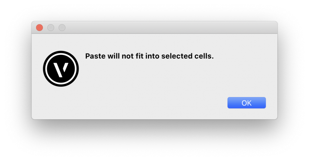
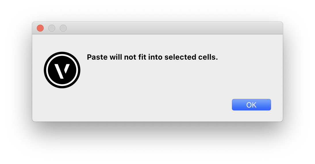
@Jesse Cogswell correct. I even created a shuttle file (pasted the cells in a new tab) before copy / pasting into VW. The key factor for me is that I can copy / paste each row, one at a time, but I get the error message if I try to paste 2 or more rows at a time.
-
@Jesse Cogswell I already did that. The interesting / frustrating thing is that I can paste 1 row at a time without issue. And none of the rows cause an issue (process of elimination). So the issue seems to be with pasting more than 1 row at a time. I'll file a bug report when I find the time...
-
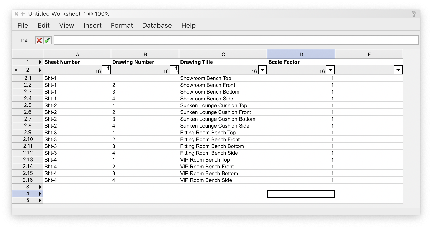
Is there a way to select any / all columns and auto fit column width (as in veritably any other spreadsheet / database app)?
-
Any chance this has been fixed in the past decade?
Experiencing the same copy / paste issue from Google Sheets into a VW worksheet:

-
23 hours ago, Andy Broomell said:
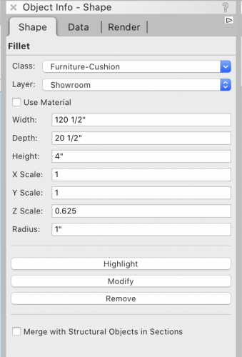
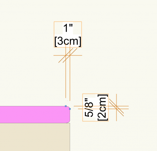
I think you'd have to start by making the pink part "taller" and with equal radius fillets, then using the Z scaling factor that solids have in the OIP to squish it. It'd just take some calculations ahead of time to figure out the correct pre-squished dimensions.
Another option would be to use an Extrude Along Path of the negative shape, then subtract that from a regular extrude.
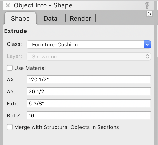
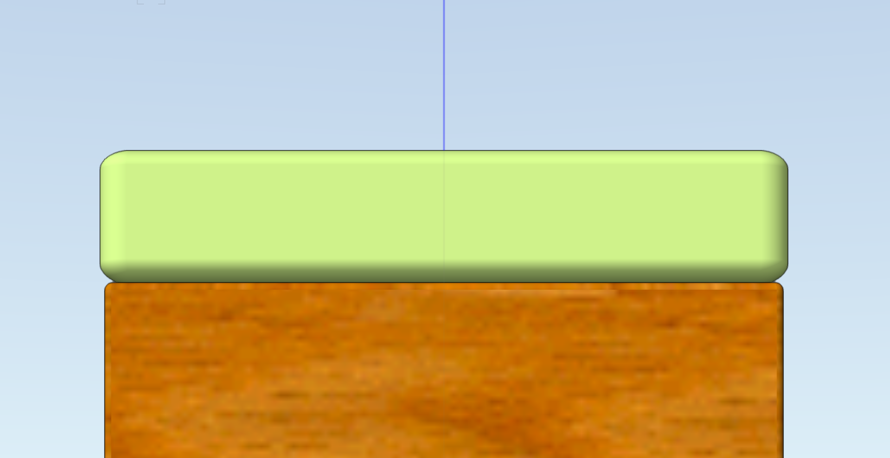
Worked like a charm--thanks!
Increased the extrude (solid) from 4" to 6 3/8"
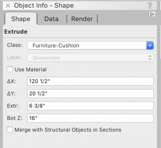
Then scaled the fillet Z by 0.625 (5/8") which brought the height back down to a squished 4"
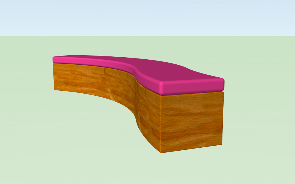
I'm sure this design will develop but it feels great to deliver a 3D model precisely as spec'd by the client.
That said, echoing @Kevin McAllister that I was expecting, and am still hoping for fillet controls similar to the Round Rectangle tool...

-
 1
1
-
-
@Andy Broomell it worked--thank you thank you thank you!
-
2
-
-
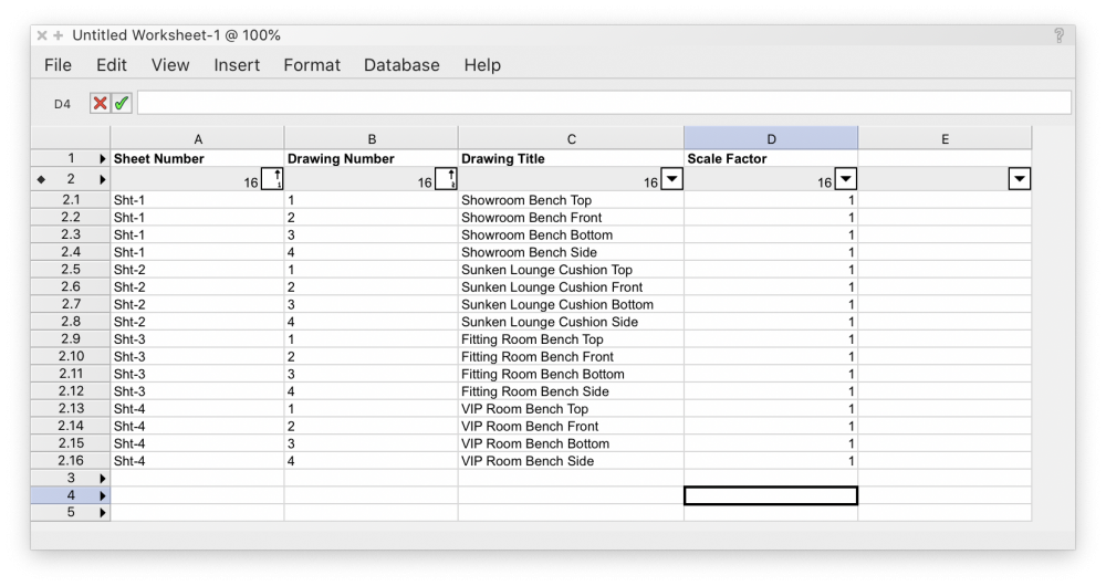
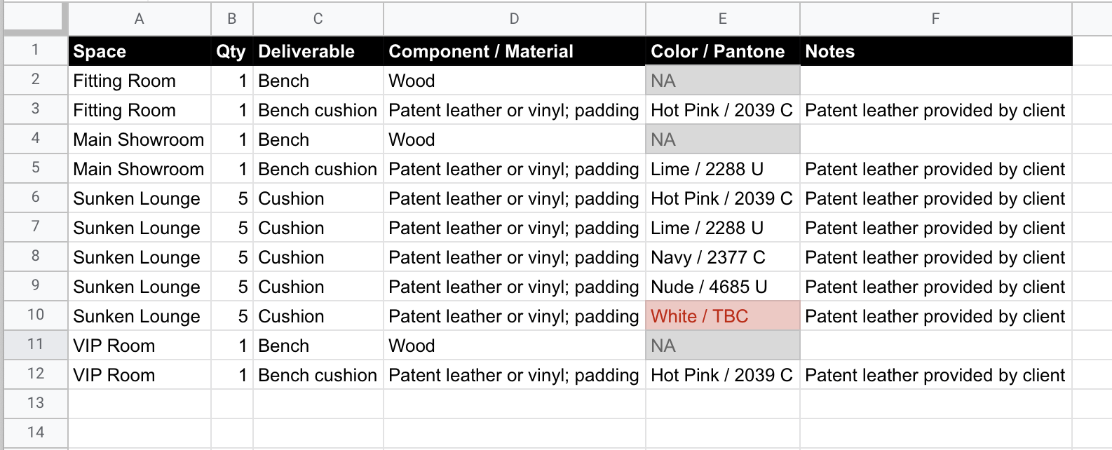
Hoping to accomplish 2 things:
- At a basic level, simply change the Dim Standard of all dims in all VP's (or selected VP's if that makes more sense)
- At a more complex level, a worksheet (not a script) that would allow me manage all dim's in the same way that I can manage all drawing labels (screenshot attached). I still feel like this is already achievable but I'm just overlooking something obvious...
For the record (pardon the pun), I really do have to dimension these objects on the SLVP's because it's the same object with 6 different view / VP's: top, front, bottom, left, right, iso
-
@drelARCH ugh, so close... but still trapped above the annotation layer to apply the attributes.
I'm honestly at the point where if I can't edit annotations via a worksheet, it doesn't belong in the annotation layer. There's just so much time and energy wasted entering and exiting annotation layers for the most tedious of edits. If I have to edit 1 thing x every VP, that's enough to ruin my day. And that would be on a good day.
-
@Tom W. not that I'm aware of. I need to change them all from Custom to Arch.
Is there a database somewhere like Callout Notes?
-
Is there a way to change all the Dimension Standards within VP's without having to. Enter. The. Annotation. Layer. Of. Every. Single. Viewport...
I tried created a Worksheet but didn't get very far...
This is why I prefer to dimension as much as possible on DL's...
-
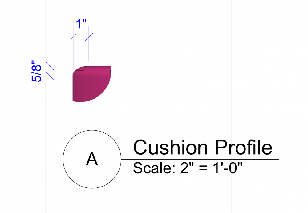
Is there a way to create this filleted edge in 3D?
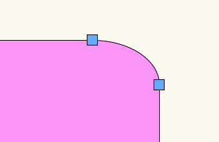
Client provided the 2D elevation. I'm trying to match that in 3D. I'm sure I could accomplish it with subdivision modeling but I'm trying to keep it simple for parametric editing as the design develops...
The screenshot below is a 1" radius:
-
On 7/15/2020 at 8:34 AM, MHBrown said:
Hi, Jeremy,
The 3D fillet tool fails all the time on all sorts of curved shapes, so it is not specific to this shape. I've tried applying smaller and smaller fillets until one works, but that is not a solution since it is not the fillet I want. It seems to be a problem with how the tool is coded.
Thanks,
Mike
I just discovered that trying a smaller fillet (1/4" in this case) works to back into a successful operation, and then I can increase the size of the fillet in the OIP to get what I want (1" in this case).
-
@_James I think it was just a misunderstanding on my part. The interior elevation marker in VW seems to be standard (across all drafting conventions). It gets really confusing when you only use 1 cardinal direction because it's just 1 "arrow" pointing in the opposite direction that the elevation is facing. For that, a traditional section might make more sense.
I'm not coming from an architectural background, so I'm still learning the nuances and best practices of properly documenting sections and elevations in a drawing set. For now, I'm more intentionally placing sections instead of just dropping an interior elevation in every available space. It's kind of a paper / rock / scissors thing for me. As @Tom W. pointed out, the interior elevation tool comes with some caveats, so it's one of those "what's the best tool for the job" choices.
-
@Tom W. that's genius! I was fighting with Shell Solid for hours but it kept failing.
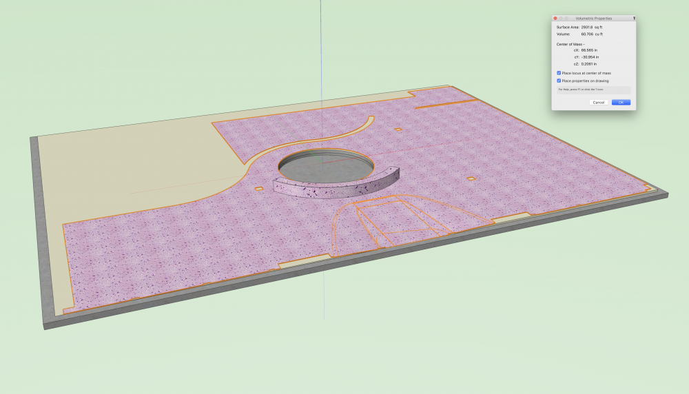
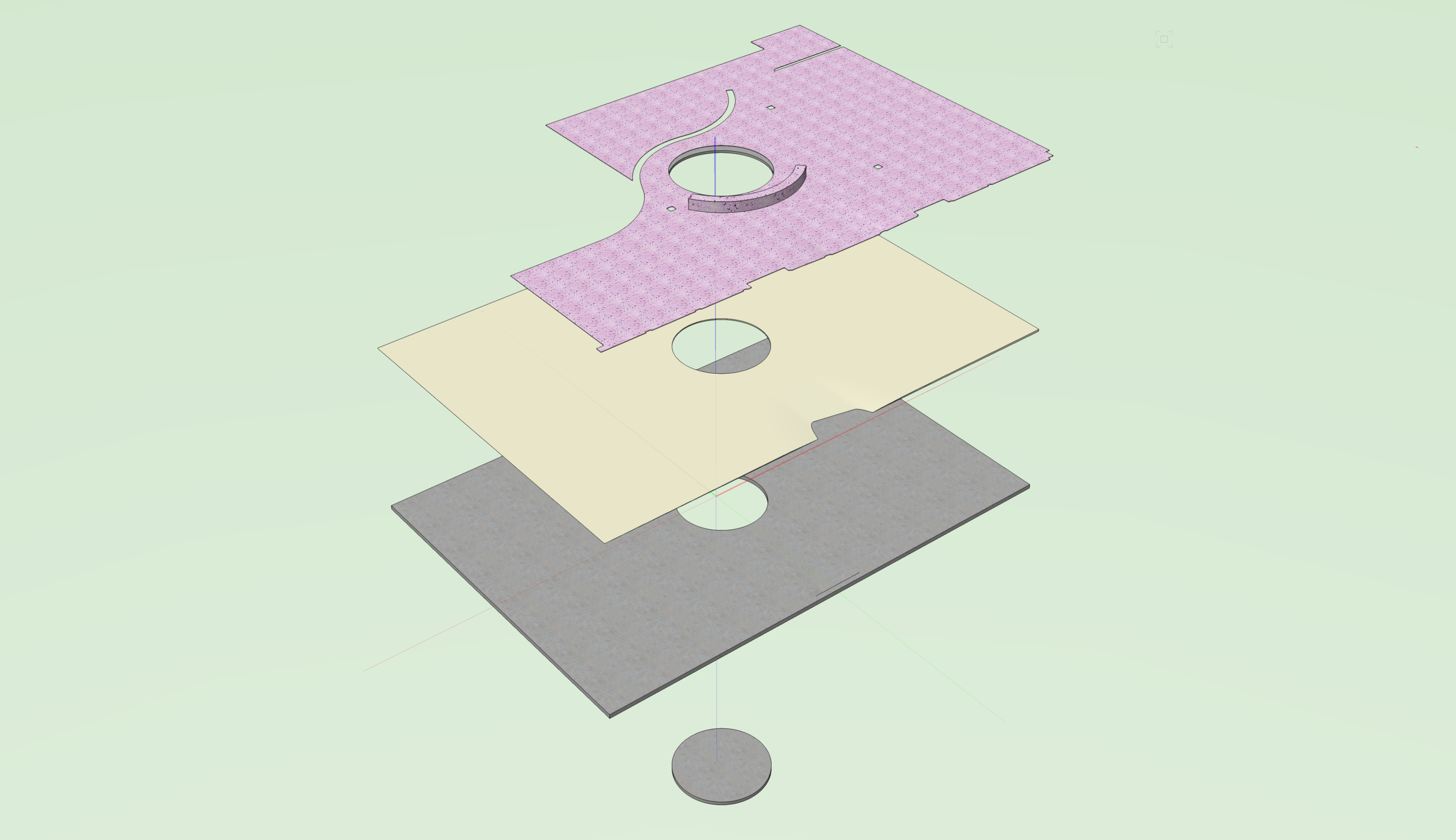
I had to fake the terrazzo "slab" by not selecting a few interior walls (that would have closed off the 2 spaces around the perimeter). I think the terrazzo layer may become extruded polys (paint bucket mode) instead of a slab object.
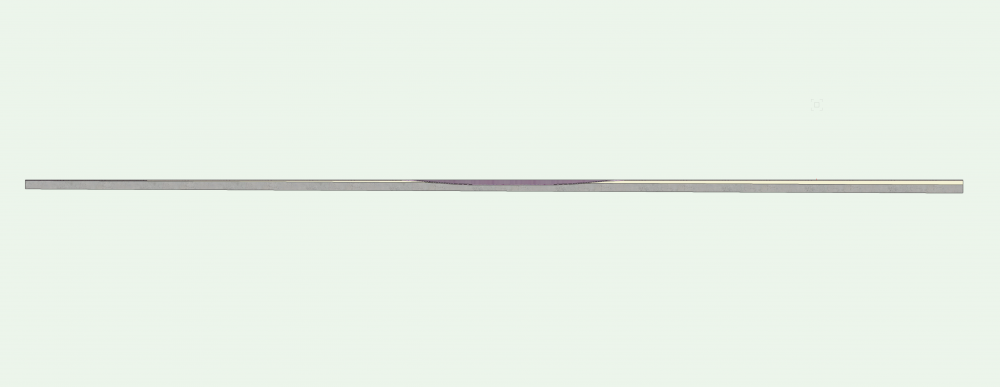
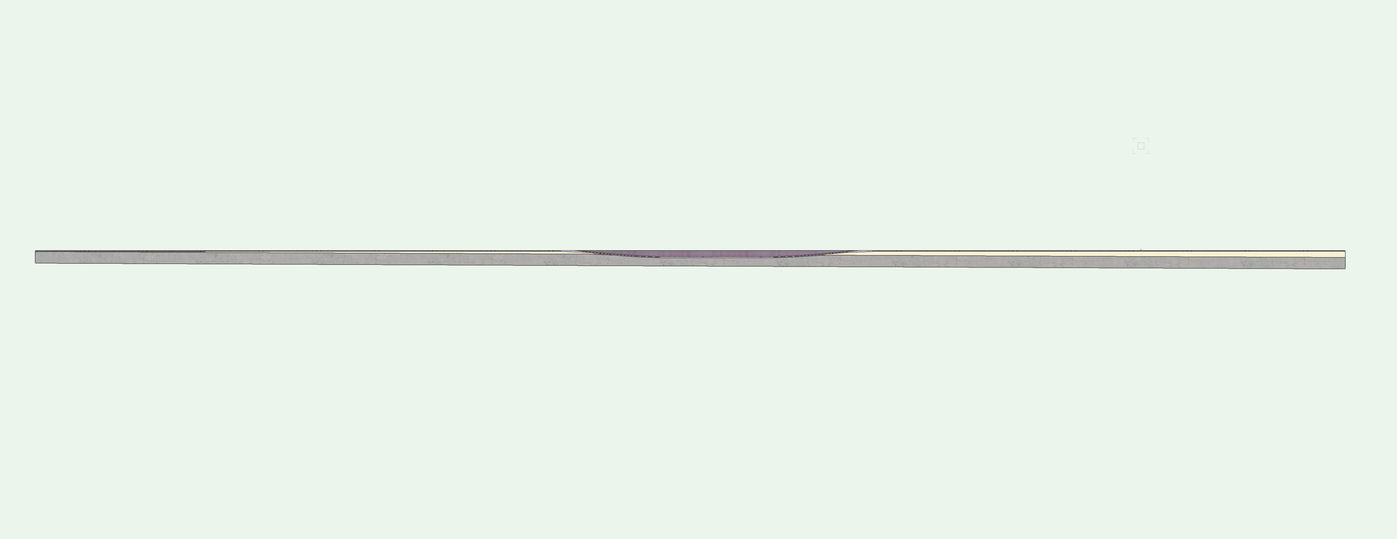
Here's where I'm at with the current method (lost or obscured the terrazzo face of the recessed slab somewhere along the way):
-
1
-
-
@Tom W. thanks--looks great! I'm curious what 3D object you're adding to the slab. Are you extracting the ramp faces, and then extruding to give it thickness?
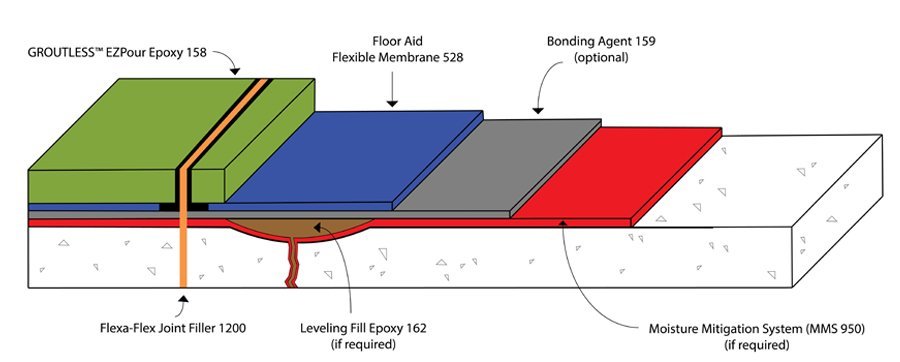
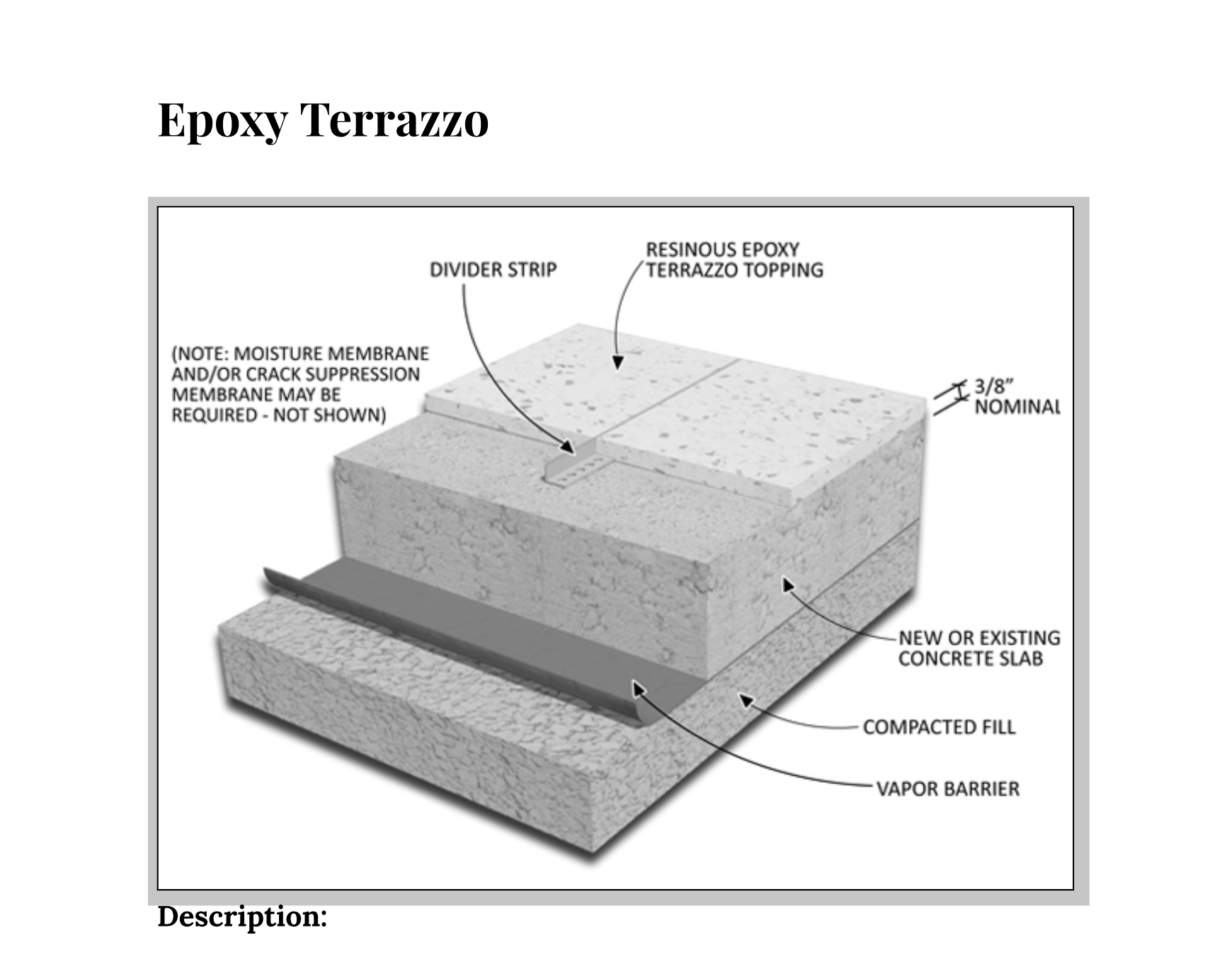
BTW met with terrazzo contractor yesterday. Cut sheets attached for reference. Revising now...

-
43 minutes ago, Tom W. said:
Thanks for sharing. Wow. Ok so I'm assuming this is an existing concrete floor which is sloping + you're laying a self-leveller on top so that the terrazzo finish is level? The underside of the concrete slopes as well like you've shown?
But if the concrete was existing presumably you wouldn't seek to cut the ramp into it as shown??
I'm intrigued!
Existing concrete slab slopes as drawn. We’re planning to self-level the floor from the highest point with epoxy sand fill, and then add a 1/2” layer of epoxy terrazzo on top of that.I’m doing a study to see how much elevation we’re adding. We’ll have to grind the existing slab for the ramp... I’m in the early rounds of working through all of this with architect, contractor, regulatory... so I just want to have a starting point to that conversation as the design develops. I’m certainly not looking forward to revisions the way it’s currently modeled.... vs my parametric hopes and dreams of simply editing a slab style.
-
v2020 attached:
-
-
The other thing I need to sort out is binding the slab component to the inner face of the walls, so I guess I just need to remove the fillet from each slab, set the boundaries, and then fillet again.
-
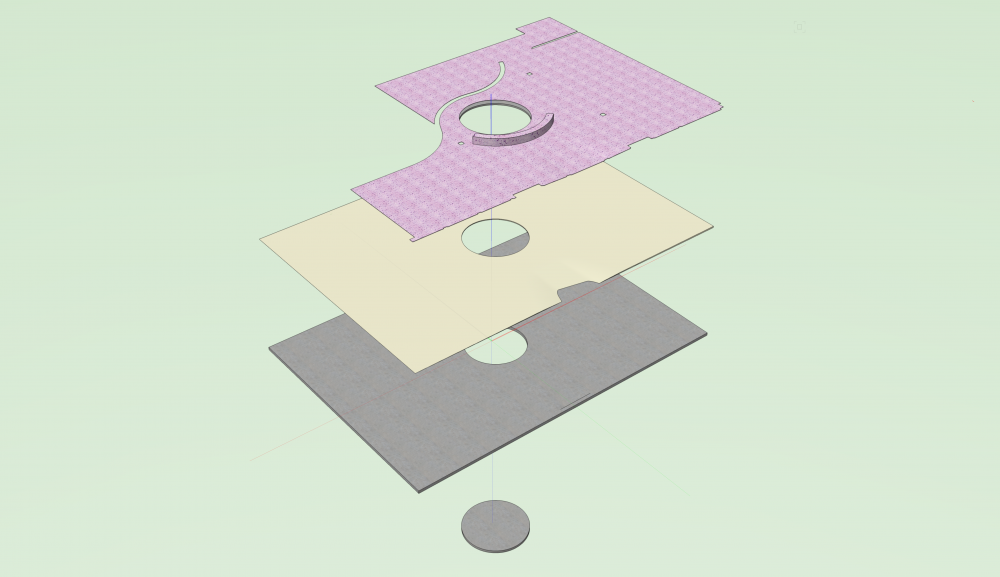
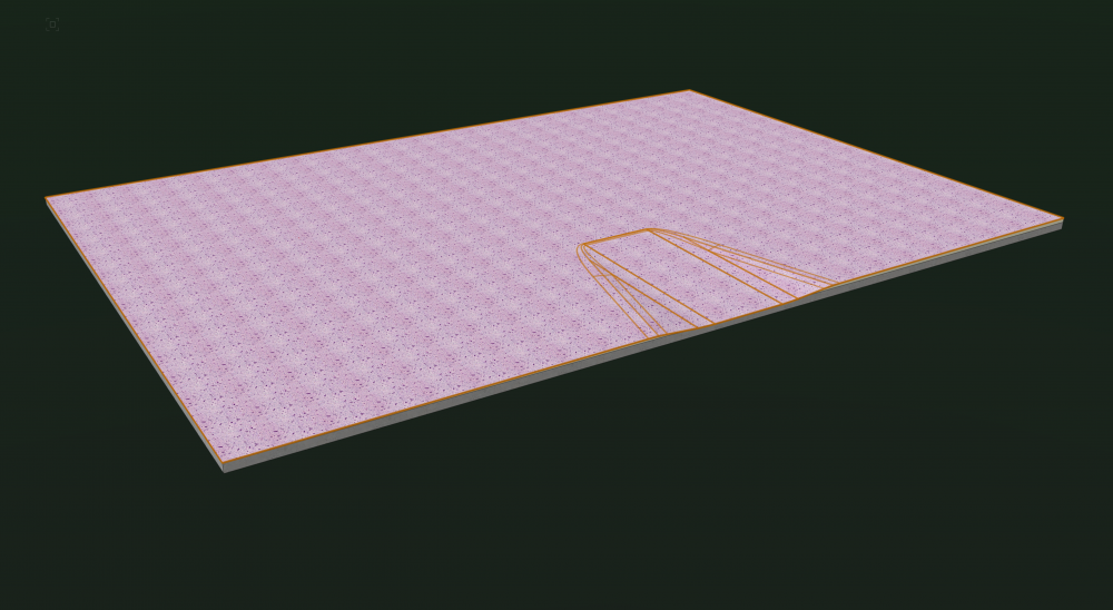
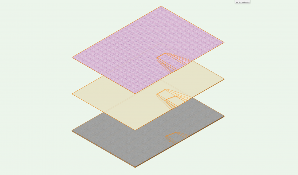
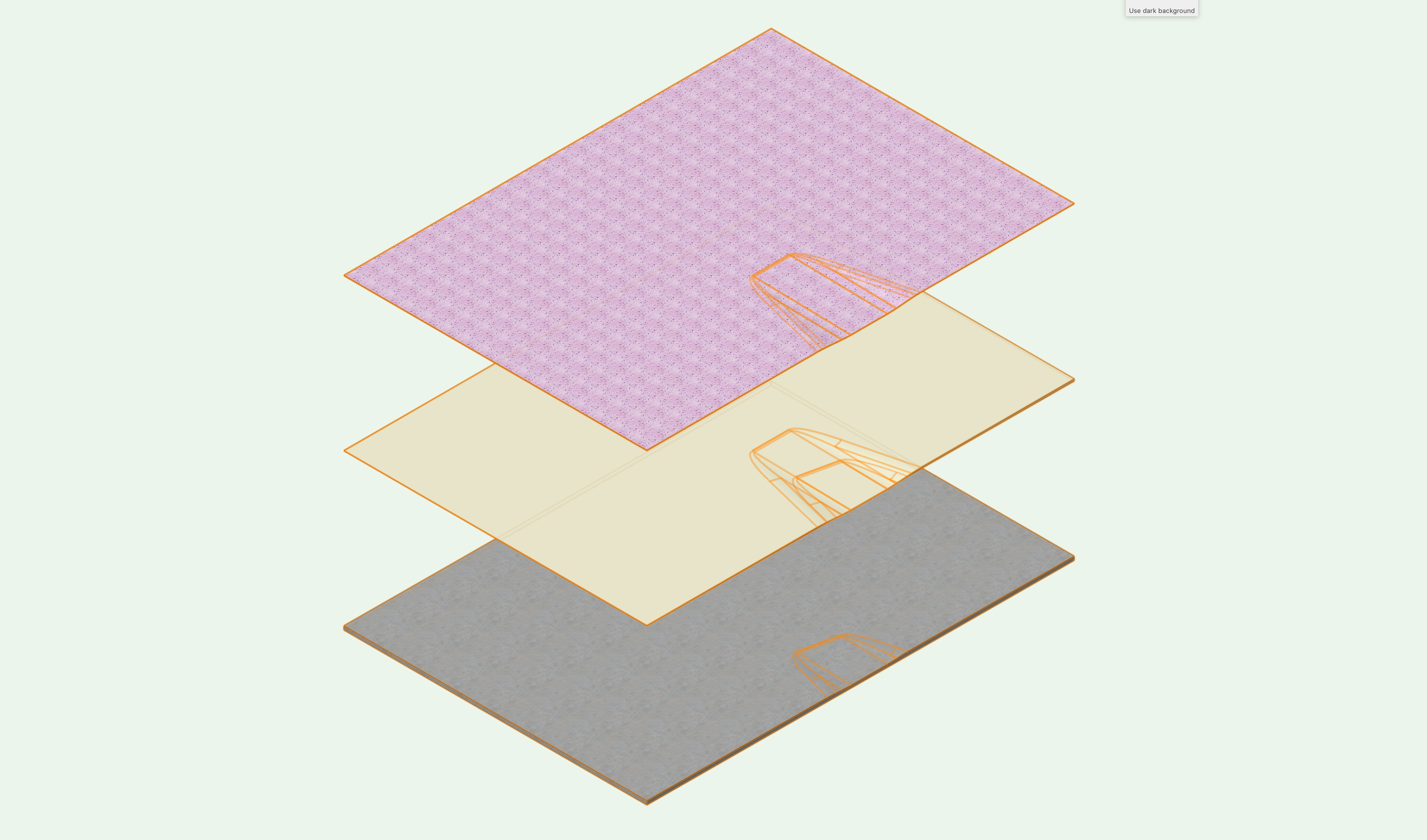
Here's what I came up with surgically subtracting the same (half filleted) 3D object (the ramp) from 3 slabs:
-
1
-
-
2 minutes ago, Tom W. said:
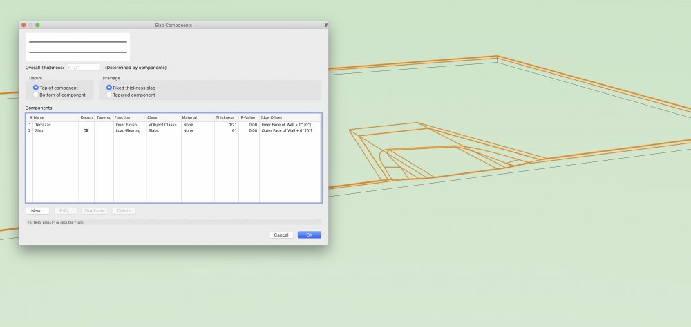
You should be able to include all the components that make up the floor construction in a single slab I would have thought
The issue I'm running into is that subtract 3D objects cuts through everything. Even if I add a component after the subtraction, it gets hacked. But what you're suggesting is exactly what I'm hoping for: a single slab with all 3 components properly layered in and leveled (still showing the slab attributes labels). Surely I'm not the first person to attempt this operation... ?
-
2 minutes ago, Tom W. said:
Not 100% sure of the specifics of what you're trying to do but I would try + apply any chamfer or fillet using the Subtract 3D Object from Slab command I.e. create an Extrude Along Path + subtract that. Then the floor will remain a Slab
I can do that for half the inner / bottom edges but not the outer / crown edges, right?
-
Actually, looks like I'm gonna have to create that 3rd slab after all (for the same reason):


Choose Plant Data Source - Plant Catalog vs VW Plant Database
in Site Design
Posted · Edited by Mark Aceto
What's the difference between these 2 options? Is there a recommendation / preference?