cberg
-
Posts
835 -
Joined
-
Last visited
Content Type
Profiles
Forums
Events
Articles
Marionette
Store
Everything posted by cberg
-
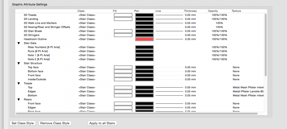
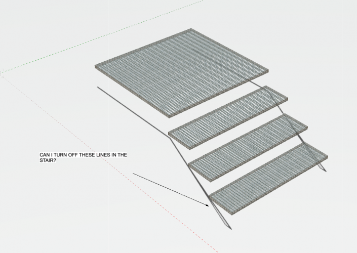
I figured it out. Under stair structure, truning off the stair structure lineweights produces the desired result.
-
This is probably an easy question, but I would like to make invisible all the stray lines associated with a stair and only have treads (so the object can be parametric). Is there any way through the control of class visibilities to hide all the random construction geometry. I tried, but couldn't figure it out. stair v2018.vwx
-
I pretty much agree with everything else on this long list. Sadly, I wish we could turn off the construction tab entirely for the stairs. That way I could use the tool for general building layout purposes only tread thickness and floor to floor. As currently implemented, the handrails and construction settings are so inflexible and architecturally incorrect as to be completely not useful. On my wishlist: Stringers that can use architectural and structural metal shapes/profiles or at least a custom profiles, as it was in the legacy custom stair tool. Why did the channel stringer option go away in the "improved" stair tool? Pickets, balusters, and handrails should have an option to link to metal profiles as well. Steel tube sizes. Aluminum extrusion profiles. Make sure to include aluminum profiles with have square edges. Not to mention decorative extrusions. Or custom turned wood profiles. Tread material customization. The other day I was searching for grating or checker plate treads, to no avail in the texture library. Many times treads are made out of a different material such as wood, or precast. Each with their own attachment requirements. Ability to customize the risers with angles, mesh, infill materials. Newell posts. Panels that incorporate mesh. Sure this could be a texture. But meshes require exterior supporting structure. Railings that can be made out of cable or rod rigging. Custom nosing profiles, again this was in the custom stair tool and it was never put back into the revised stair tool. Or if we can't build this any of this into the program, we need to attach 2d view options to each of the 3d elevation and section components so that it can be accurately represented in 2d.
-
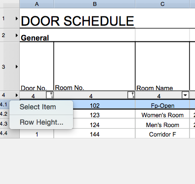
If you double click on the worksheet and edit it, you should be able to right click on the row and select the item. This should take you to the door in question. I do this in one of the design layers and make sure all the layers are on.

-
I need a texture for polycarbonate sheets.
cberg replied to Sofia Ames's topic in Resource Share - Textures
Thank you Jim. I appreciate the resuscitation. -
Thank you. Somehow I thought the unconstrained mode defined the shape of the section cut. ( Like it would create developed sections or elevations) However, it doesn't seem to do this. I need to read up on this tool! That said, you are correct the second (unconstrained) mode allows you to manually link the marker to a viewport as it used to. Thank you!
-
In VW 2018 the section elevation marker tool would allow you to manually link a viewport that you wanted to associate. This was somewhat useful when developing 2d details/elevations that related to a model or plan of something. I always told folks in my office that this was an annotation function, and that modeling section cuts happened through View menu bar, by creating a section viewport. The 2019 version of this tool introduces an ability to create live sections from the section elevation marker tool. However the ability to manually link the viewport to say a 2d viewport seems to have gone away. Is this a bug, or the new normal for this tool?
-
I need a texture for polycarbonate sheets.
cberg replied to Sofia Ames's topic in Resource Share - Textures
Is there a file or link associated with this post? -
Thanks, gentlemen. Do we know whether this has formally been submitted as a bug?
-
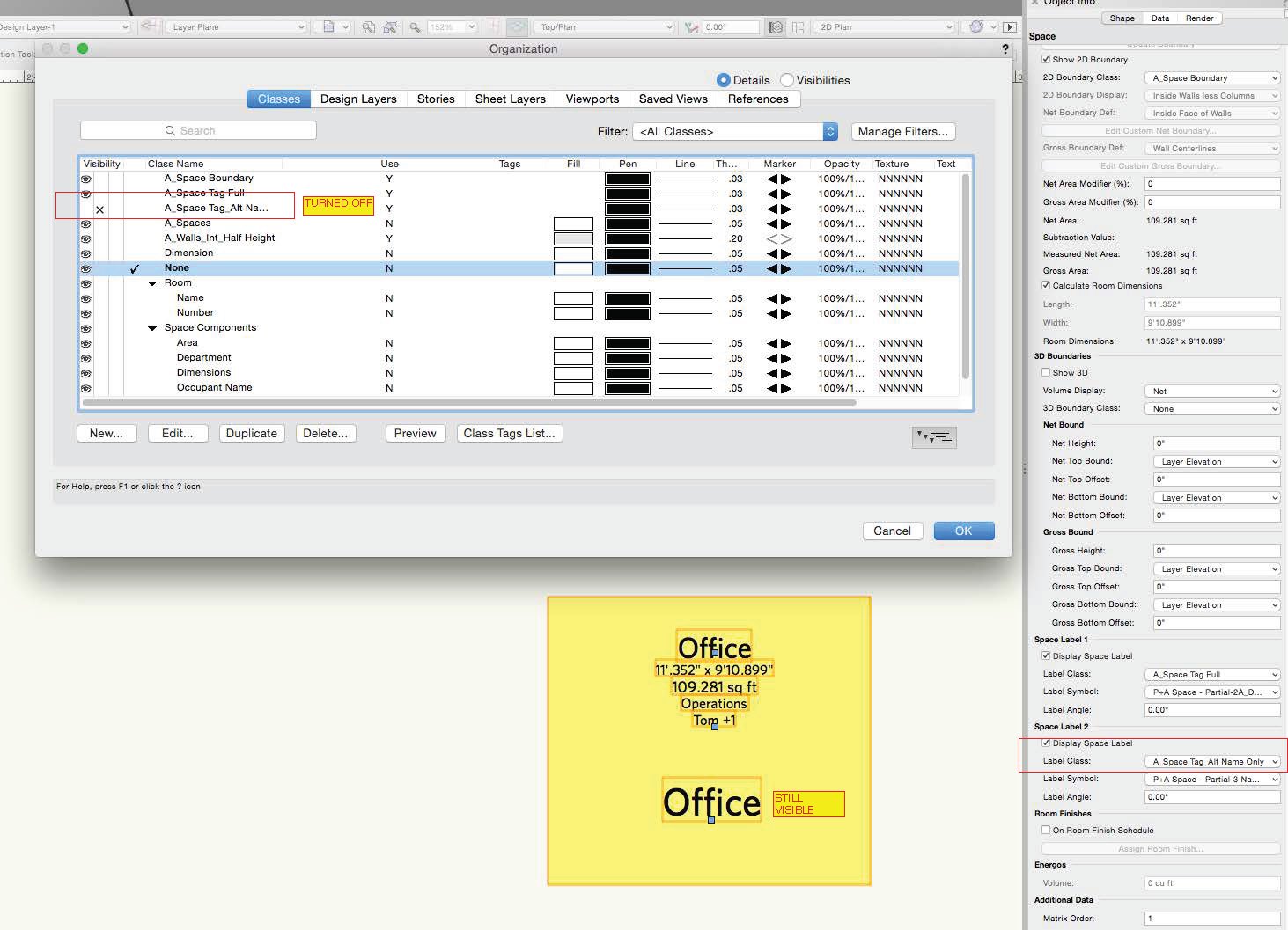
It's unfortunate that multiple space labels cannot be turned on and off via classes. 2019 SP-1 does not appear to have fixed this issue.

-
While it sounds simple, in the example listed above, it requires constant math when working with multiple sets of layers. It is very easy to make mistakes when there is not a global Z coordinate system.
-
Okay. This may not be intended. However, if you group the objects with the layer you want to move everything to activated, and then ungroup them, the objects are reassigned to the desired layer without being adjusted in 3d.
-
Is there a good way to move objects between layers with different Layer Elevations (Default Z Values) without having to manually adjust the objects in the z axis? For example, if my layer 1 elevation is 10' and layer 2 elevation is 20' reassigning an object from Layer 1 to Layer 2 requires me to go through the added step of moving it back down by the difference of the two layer elevations. This is confusing to most users and a potential source for modeling errors. Ideally, there would be a script or command to Paste in place to the absolute z value of the object, irrespective of the layer elevation. Does anybody know of any tricks or tips?
-
Merge with structural group unchecks when modifying a generic solid
cberg replied to cberg's topic in General Discussion
VW 2019 seems to have fixed this! -
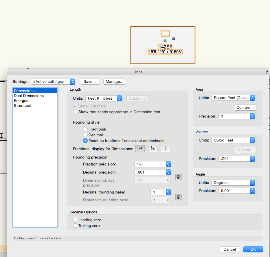
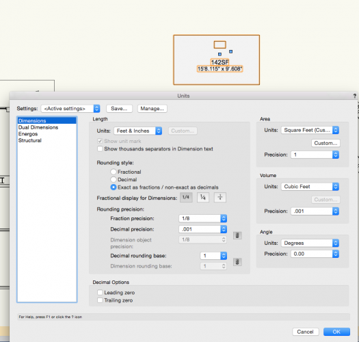
Under document settings _ Units _ Area Units. Select Custom. Then you can change the suffix to whatever you want.
-
A few weeks ago I was thinking about purchasing them for our office. But now I guess we are out of luck. One can only dream that VW may have purchased the entire collection and plans to add it to VW2019.
-
Just noticed that the VBVisual Website is not operational. Does anyone at VW know anything about this? http://vbvisual.rendermall.com/shop_content.php?language=en&coID=13
-
Let me think about that as well. In the past, we've had issues with models set at the height above sea level. Maybe this was with older models that were started before 2018. But the unified view options acted super funny. Zooming to the model extents became problematic. Or maybe there was user error.
-
Let me experiment a bit with this idea that to see how everything works.
-
What makes you think it will change again in 2019? Just curious?
-
Is there a way to set a datum elevation of a terrain model? For the past year or two, I've been making terrain models by using 3d loci that have actual 3d elevations (above sea level). This means that that site models are hundreds of feet above the Z=0 Plane. Architecturally one typically sets first-floor elevation at 0'-0". And typically architectural model layers are set up much closer to the ground (so to speak). To bring a building and a terrain model together, I typically establish an arbitrary datum elevation and move a copy of all the site model elements (including modifiers) down to meet the building. However, once doing so, none of the topo labels are accurate and making any changes to the site or its modifiers is tricky (requiring math). How do others handle this? Is there a way to recalibrate the terrain model labels so that actual topo labels read correctly? Or are there other techniques for bringing these two design elements together? I have found referencing a terrain model present problems with section viewports, so I don't do that. Maybe there are functions in the program that I don't fully understand. How do others bring site and building together?
-
Has this changed for VW 2018? I am having difficulties with the Database Headers. Since they have changed.
-
Do you need to be on Facebook to see the live stream?
-
That's what I was thinking...
-
This is awesome! Might there be other benefits associated with the switch of the sheet layers to the Vectorworks VGM? 😏 Specifically, would this enable viewports to be updated in a multithread fashion, or perhaps continuously?