Search the Community
Showing results for tags 'walls'.
-

Opt Click in place to set Wall Endcaps
bcd posted a question in Wishlist - Feature and Content Requests
I'd like to opt-click to set a wall endcap in place - rather than determining which is the start/end of the wall and then finding the appropriate dropdown to click in the OIP, mouse down to and select.-
- 1
-

-
- architecture
- walls
- (and 2 more)
-
 The parametric wall tool that is default to VW is nice but I want to know if its possible to take it a step further. I am trying to find a way of distributing objects or extruding custom profiles horizontally and vertically across the surface of a wall efficiently to create things such as flashings or cladding. Ideally being able to click and drag a wall like you would with the wall tool but automatically generate and space specified extrusions or recesses across its surface. On one of my current projects I am using the curtain wall tool to create a second wall on the outside of my exterior walls that represents the 4x8 reveal panels and it works quite well. See attached screenshot. Theoretically the curtain wall tool performs most of the functions I want to do, but it is restrictive. I need to create two windows at each opening to cut the curtain wall as I cannot find any way to combine or link multiple walls so one window cuts through both (Is this possible?). The curtain wall tools frame and panel options are limited and do not allow for the use of custom profiles (custom profiles are a big deal when I need to model something after a specific product). So what I am wondering is wether there already exists or if its possible to create a function or tool (Maybe with marionette?) that functions similar to the curtain wall tool but is more customizable and less restrictive. Another Issue I have yet to find a good solution to is the inability to fillet or chamfer the edges of plug-in objects like doors and windows (or say the edges of the frames and panels of the curtain walls above) without losing their parametric abilities. I do a lot of rendering and having soft edges is important for realistic lighting. I have a feeling all this and more could be possible with the marionette tool, but I have yet to set aside the time to start learning it.
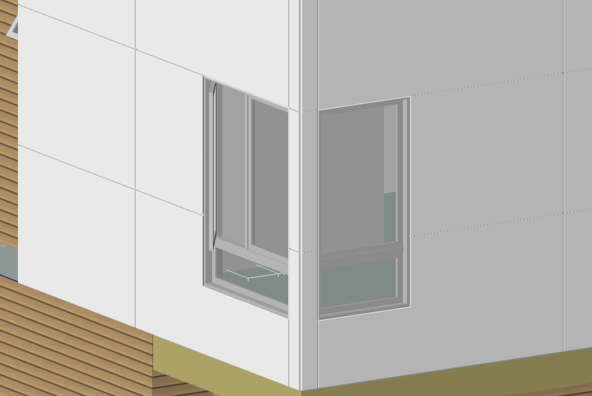
- 4 replies
-
- 1
-
-
- walls
- marionette
- (and 4 more)
-
I know it's possible to create a slab from walls, but is it possible to do the opposite, create walls from a slab or 2d polygon?
-
 I regularly create landscape retaining walls in my drawings using the wall tool. The landscape wall tool has never really worked for me as it seem to be for very large landscape applications and far more involved to use, at least that has been my experience. I would like to see the ability to add a top cap to a regular wall via the OIP, perhaps providing a cap option of height and width. I have, in the past, used an extruded these but it's a real pain when the wall top is sloped vs level.
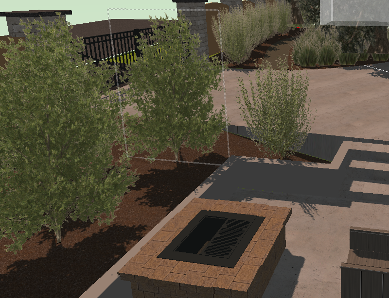
-
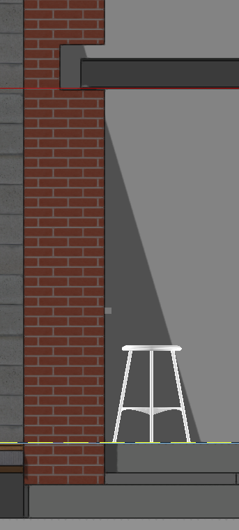
The following is a problem that has plagued my files for awhile and im afraid will be a quite a noob problem. All the walls in my projects are classed Walls External or Walls Internal. Each class has a render setting to the right and left of wall. In the attached image I have selected weatherboards as the left render style. Looks fine apart from at some junctions the textures don't line up. Im guessing this is because somehow the texture is linked to the boundaries of the object as opposed to more of a world based setting (similar to ho hatches work). In the Render settings I have chosen auto-align plane for both walls however the two textures still don't line up. I know I can manually adjust the vertical offset but hoping to find away to have all walls set up when drawing so that regardless of texture chosen they will all line up unless specified otherwise. Can anyone point out where I am going wrong? Thanks in advance.

-
Are there any tricks for trimming walls to roofs, where there are more than one object on the roof layer. For example I have a roof that I want wanting to extend my walls to. However there are also old roof objects which are classed as removed. There are also beams etc that get in the way. I had hoped that by turning these other classes off that the walls would trim to the visible roof. I know I can create new layers and then move the roof there, trim and then move back. Seems like a roundabout way to achieve something simple.
-
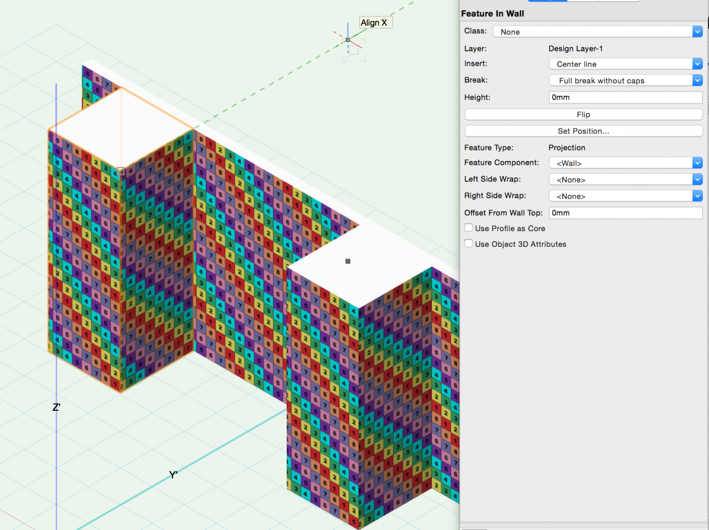
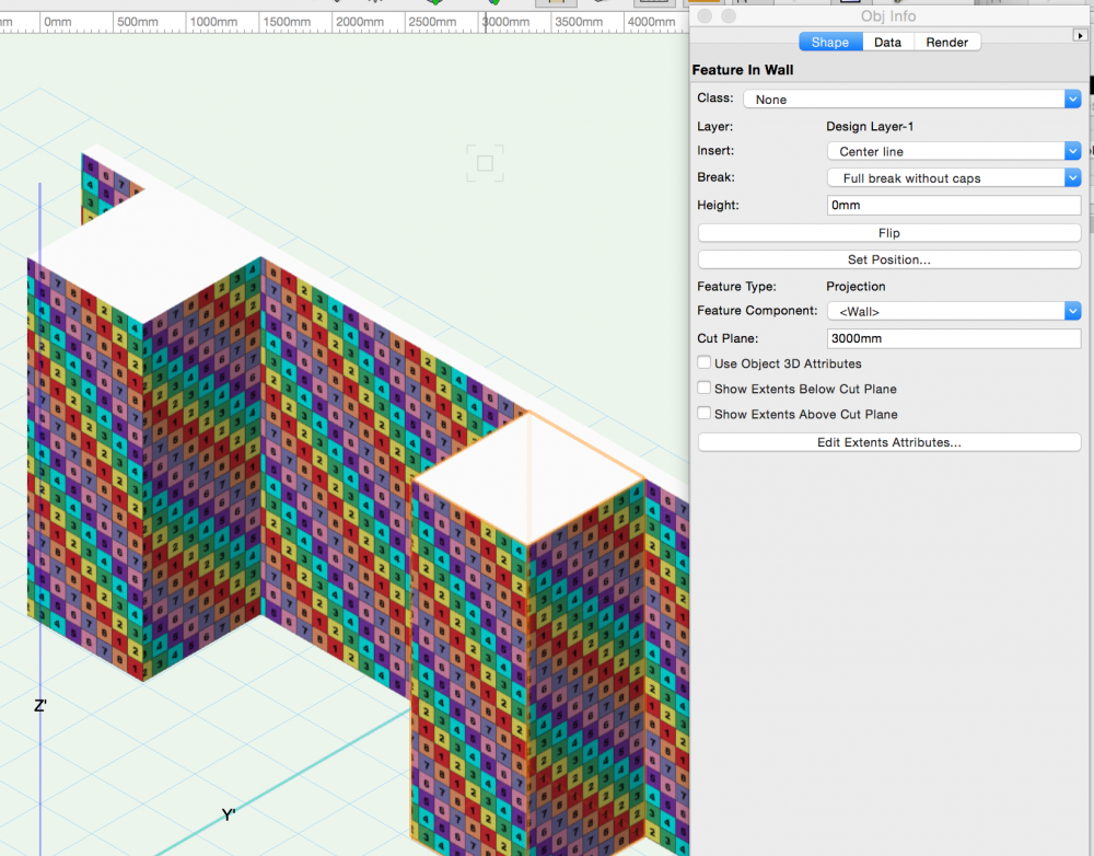
I need a bit of help here as I am confused about the Feature in Wall object. I got to this via trying to texture a feature in a wall which ended up being a total mess. In this post I am looking at wall projections only and not wall recesses I can create a feature in 1 of 2 ways: 1. A 2D shape touching the wall then select wall and shape and right-click and add surface. There are other ways but this is easier. 2. A 3D extruded shape touching the wall then select wall and object and AEC > Create Wall Projection. in both cases the features are Walls and not objects (objects btw are totally broken since 2012 at least). In both cases I end up with a Feature in Wall object but with very different parametrics (see attached). I tried in the help but mine is broken as it won't list the topic (need to look at this further) So after all that if I create from a 2D shape I get the options 'left side wrap and right side wrap'. Both have none as the dropdown so does anyone know what these do? thank you
-
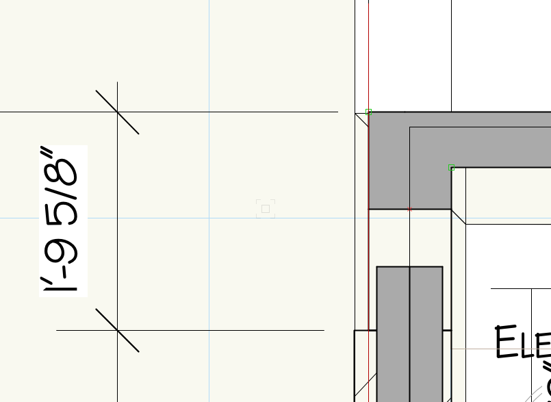
Here is an elevation of a beam pocket drawn with a window opening in the wall. As you can see the floor plan shows the opening and the beam, how can I avoid that. I suspect I am not doing that the right way. Could anyone help me out on how to do that the proper way. Note that I tried to do that with a wall recess but I end up with an exterior wall flange on the right side of the opening. Is there a way to limit the height of the section for the floor plan? Any help is much appreciated, Thank you all

-

Wall With Interchangable Assemblies
Tom Klaber posted a question in Wishlist - Feature and Content Requests
This is a little complex, as it requires a subtle conceptual shift in the way walls and wall styles work - but I think it would be worth it. The wall styles are great, but when you get deeper into DD - you realize you need way too many to cover all the situations you need. If I need three stud sizes (1,2,3), and three finish assemblies (A,B,C) I need 18 wall styles! - A1A, A1B, A1C, A2A, A2B, A2C, A3A, A3B, A3C, B1B, B1C, B2B, B2C, B3B, B3C, C1C, C2C, C3C. I think the equation is (nF(nF+1)/2)*(nC). Where nF is the number if finish assemblies, and nC is the number of core assemblies - (Now known as Tom's Equation. Math people please correct if I am wrong). This can get out of hand quickly. Obviously, you do not necessarily need every combination - so your true total will less than Tom Equation - but the issue remains. We realized this when doing our wall type pages and started to develop a new wall type system that I think holds the answer. Rather than every wall being a fixed style that has to account for every combination of finishes, walls should be broken down. Walls would be composed of mixed and matched assemblies consisting of 1 core or structural assembly and 2 finish assemblies. This could be handled in a similar way to how the Rendering tab thinks of walls: core, left, and right. Right now - the only way to handle wall styles is to dumb it way down. We try to lump all finish assemblies into GWB / Stone. Even with that - we usually have at least 5 different core assemblies, then several rated versions - not counting exterior wall constructions. We can quickly balloon to 20 - 30 wall styles, which is pretty cumbersome and even with that do not achieve the degree of precision we would like. If the finish schedule and wall styles are tied together and controlled via the OIP for the wall - rather than the space object, you can get robust control that easily scales as a project progresses. The project could start with 1 finish assembly, then move generic categories, then when in CDs, the full finish schedule could be applied to walls. The idealized future benefit of this would be the ability to paint bucket finish assemblies onto the core assemblies without having to change the wall style. As an added benefit to the increased precision, this would then let VW 'know' precisely what finish is being called for and then schedule that information, create keyed finish plans, and display the wall with dimensional accuracy.