Search the Community
Showing results for tags 'location'.
-
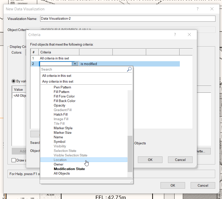
Not sure if its being documented anywhere, and can't seem to find in help articles, but does the Data Visualization Object Criteria settings disable 'Location' by design? or is this a bug?
- 10 replies
-
- 1
-

-
- data visulization
- location
-
(and 1 more)
Tagged with:
-
Hi all, I'm starting with some basic marionette stuff to get a better understanding and I'm running into a little bit of a problem that I can't seem to figure out. I've created a small script which creates a rectangle and uses control geometry to determine the size of the created rectangle. Once I wrap the script and convert it to an object node with control geometry the object, the control geometry and the generated rectangle become misaligned. Furthermore, when i adjust the size of the control geometry the origin of the generated rectangle seems to shift. Does anyone know why this might be happening? I've attached a screen shot of the issue below. Thank you, Derek
- 4 replies
-
- marionette
- control geometry
-
(and 1 more)
Tagged with:
-
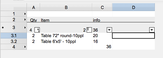
I have a number of rooms on my drawing, and each room has a closed polygon around it that I've named that given rooms name, so when I want to summarize all the items in each room all I have to do is create a worksheet with criteria that's pretty basic. All the items on layer 'Room items' that fall within the location of 'Room1'. This works great, but what I'm struggling with is how to call out the location name 'Room1' in the resulting search criteria cells (if that makes sense). i.e. in the attached file, I'd like cell D3.1 and D3.2 to have the name of the location the items were found in. Any thoughts?
-
Hi there, I have put together a drawing and want the worksheet to count nested symbols in a specific area of the drawing. I have named a rectangle area in the drawing "000-OrderArea", and they Symbol "ProjectSeat" appears in this area both on its own, as well as being nested within two other symbols. Here is the formula in the Worksheet cell: =COUNT((INSYMBOL & (S='ProjectSeat') & (LOC='000-OrderArea'))) The Worksheet is only counting the 'loose' symbols in the area, not any of the nested ones. Any clues as to how I can get it to count ALL of the symbols in the area? Cheers, Nick
-
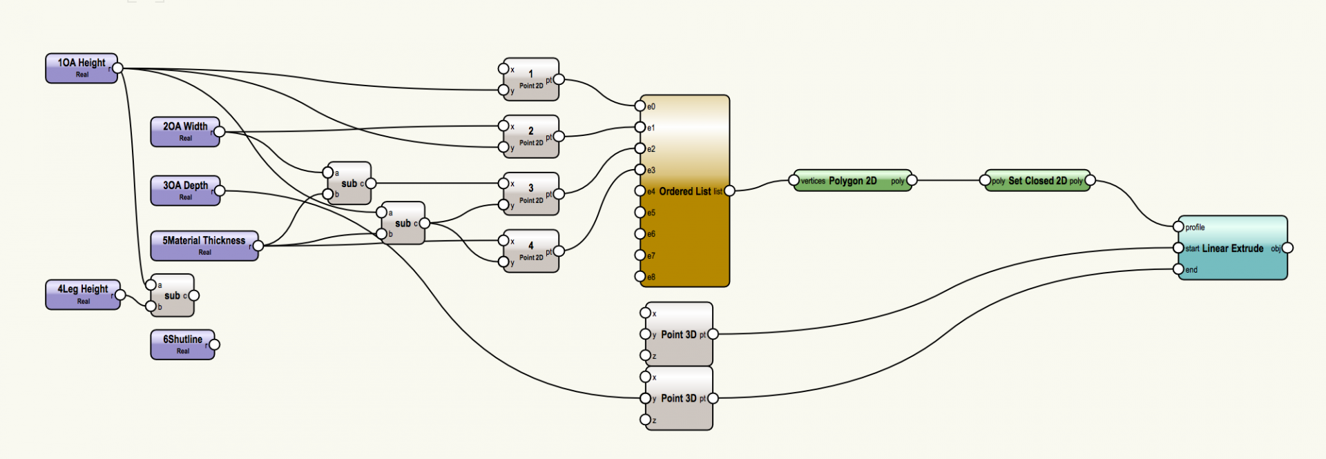
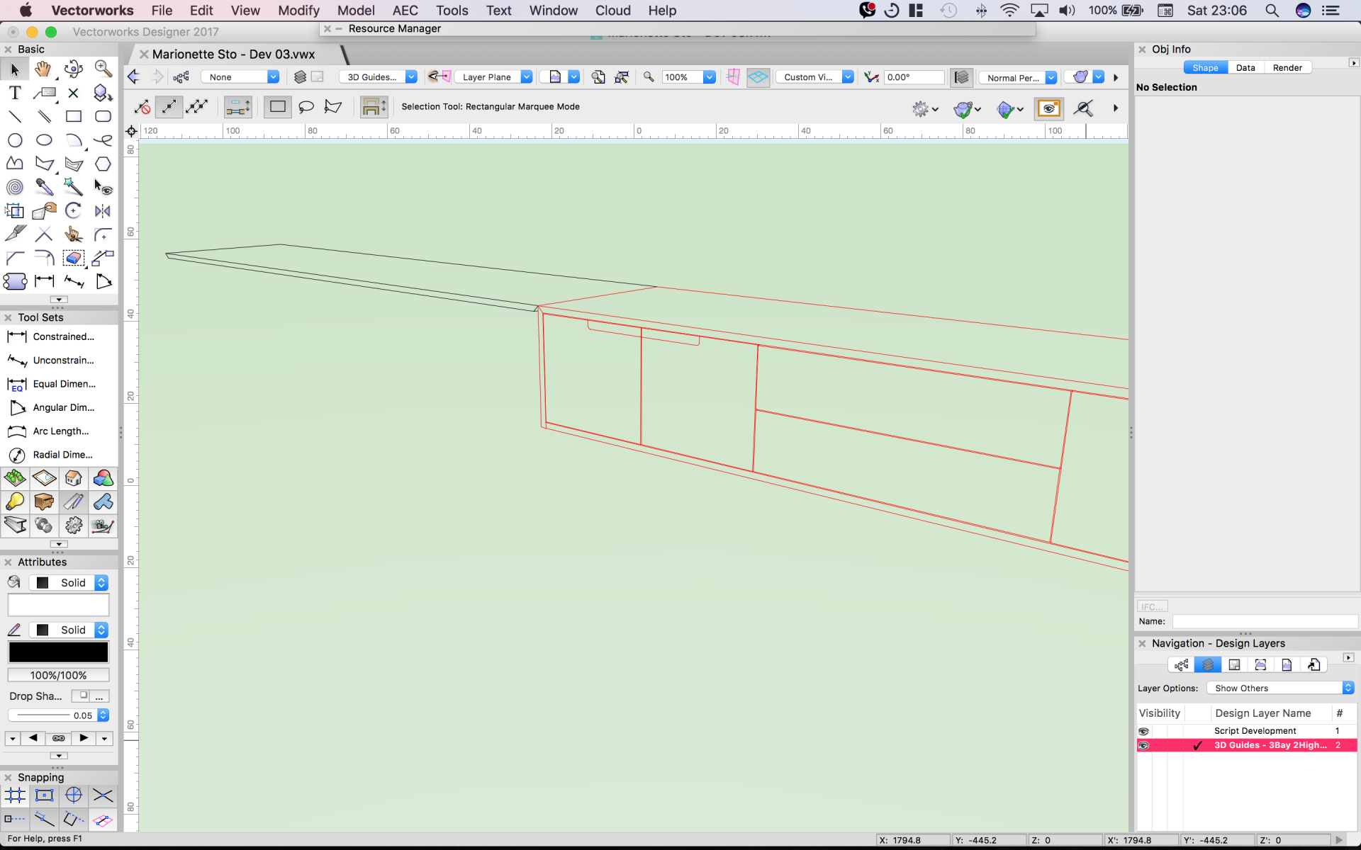
I'm exploring the viability of using Marionette to create bespoke cabinets. They will vary in H, W, D, number of bays and bay components. I intend to use the script to generate several outputs; a simplified 3D model suitable for Hidden Line rendering used to illustrate the configuration; a detailed 3D model with panel gaps, filleted edges and individually orientate-able woodgrain textures suited to presentation Final Quality renderings; and (eventually) cut-lists derived solely from the input parameters. - But I'll start with just the simplified 3D cabinet first. I'm at the early stages of still figuring out what Marionette is capable of and how to achieve things that seem possible that will enable the above. As a result of seeing the impressive post by @DomCthe "parametric metal framework cabinet" I decided learning Python would be necessary, but it's slow going so I've returned to experimenting with Marionette nodes as-they-are, especially because of subsequent enhancements to Marionette's repertoire. Currently I'm stuck trying to make Extruded 2D polygons spawn at the desired location. I'm testing using the top panel of a long TV cabinet. I created the top panel's profile and prescribed it's location by using four point locations. The network achieves this up until the 2D polygon gets created, but when the Extrude node goes to work, it gets put on the opposite side of the Y axis. How do I control this? Or is there a better way of crafting and positioning these panels? (Note that many panels will have at least one mitred end so I can't use rectangles and standard extrude nodes). I'm now thinking about lofting between two profiles for each panel, but this is getting rather busy... Does this interest either you @Marissa Farrellor @DomC? Any help or guidance on offer would be great. Thanks! Marionette Sto - Dev 03.vwx
- 5 replies
-
- marionette
- cabinetry
-
(and 2 more)
Tagged with:
-
I vote for advanced Project Info in File. All Project Info Data needed which can be and managed at one place. Like Geographic Location and Elevation of the Site, Authors and Office Adresses, Project description, .... So that these things can be used as the default settings when creating Heliodons, for IFC Exports, for Energos, for Sheet Borders, .....


