
MattG
-
Posts
655 -
Joined
-
Last visited
Content Type
Profiles
Forums
Events
Articles
Marionette
Store
Everything posted by MattG
-
I have a drawing I am working on with a bunch of symbols made up of other symbols. I am making a report to show me all the info on the symbols. Is there any function or way of showing a field that shows what symbol a symbol is in? For example I have 5 of symbol A and 8 of symbol B put together to make a thing. I make that thing a symbol and call it symbol Z. I have a report that now shows all the symbols and their record format which is what I am really trying to get out of this. However they are just all in one big list. Is it possible to put in a field/column that shows the parent symbol and then summarize by that field/column? Not sure that totally makes sense. Matt
-
Yeah I am not sure what the best option is. I hate to dig too deep because it should be a rare occurrence. However the first option of a self script would probably work.
-
That was what I saw just looking through this forum, looks like ODBC would be the way to go, but right now I'm not sure I have the want or need to tackle that. I was hoping there was maybe some sort of a great script or something that could basically replace all instances of an existing symbol with their self. That would solve my issue. Matt
-
This is kind of the jist, basically I have this x100's. So say I change the value for any of it but specifically the cost value. It will change in the resource manager and be good for putting into new document. However in my actual file I made a few sheets that show all the symbols laid out for reference. None of the ones in that file are updated unless I either manually insert again 1 by 1 or replace and replace 1 by 1. Super frustrating.
-
That's not exactly what I'm trying to do. That worksheet works for objects inserted in the document. I am using this file as a resource file. i.e. the symbols I'm wanting to update are in the resource manager, not the symbol instance that is on the document. This file is just a referenced file in my resource manager after I hit save. So one of the things is that I want to be able to open the file, edit the symbol in the resource manager and have the instances that are in the drawing reflect the updates. Main thing is we are doing some custom build stuff right now but using known pieces. The known pieces, nuts, bolts, etc all have known costs. A good example is I am entering the costs today. However in a week the costs may be different. I want to be able to open a new document and have all the symbols I grab from that referenced file have the right cost. However if I were to open the file and click on an inserted symbol its cost would not actually be updated. Does that make sense? I can make a video if that is helpful. Matt
-
I am hoping someone has a better way of doing what I am looking to do. I have a bunch of symbols. I made them semi quick for a project. I attached a basic record to them with about 4 fields and made a quick worksheet. I made a resource file from them just showing them all in space with labels next to them for easy reference. I have since added 4/5 fields to my record to get a bit more detailed. I updated the symbols in the resource manager. Here is my question. Is there some better way to get existing instances of a symbol already in a drawing to "update" with updated record format information? Right now my process is to select a symbol (any with the name) and replace with something, then replace back to what they were. But in my resource file I have just one of every one laid out on my workspace and I just wish there was a easier/better way for this. Anyone have any thoughts? Thanks, Matt
-
@Wes Gardner Thanks for that. I'm using a non story wall style and it works for what I am doing. While believe me I get the idea of having things structured a certain way to help with automation etc. It was just frustrating not getting it for a bit there. Either way I think I am okay for now. Matt
-
Thats what I would have thought, but see this video. What am I doing wrong?
-
I consider myself very competent in VW and use it all the time for spotlight work. Now I bow down to get a hand using the Architect tool set and wall tool. I started a drawing with the Architect.sta file. I am literally just drawing a bathroom for a friend to do a remodel on and trying to draw in notes for the contractor. For some reason the way the wall heights are determined seems to baffle me a bit between layers and story height etc. I guess a few questions here. 1) Does someone have some good guidance, video, pdf, direction, on how wall heights are controlled? It seems tricky for someone not familiar to fully understand. 2) is there some way to use walls without having the heights determined by layers, story, style, etc. In my current example I am using the wall style "Int Wall-2x4-Gyp Bd 5/8in" Looks correct. The heights seem to be correct but they are based on the story/layer set up. What prompted me on this is I have two areas we are wanting to draw in a half wall. One is one of those walk in showers where the bottom half is tile/stone with a sheet of glass above the other is just more generic. I tried changing the top and bottom bound setting and changing the height but it still stays at the same height as the other walls. What is the best way to do this? In the mean time I am just drawing extrudes etc, but I have to think this is not the right way of doing this. Thanks, Matt
-
Wow, I clicked on this and didn't realize what it would evolve too.......this is interesting. Only going to throw out a couple of small nuggets on my opinion. 1) On the actual idea of PD's etc in VW. I have along with others have made a file of most of our PD's. Main purpose is for 2D/3D geometry, not for any sort of smart functionality, but they do have records attached with notes like power service fed from size, and a few other more basic things. However speaking from our industry, I know that essentially all of our distros are specific to us and not industry standard (one big thing is we wire them differently) either way which means they probably aren't terribly useful for any other users. In moving to a 3rd part or built-in plugin that opens the door for super levels of variables in equipment between manufacturers, vendors, end-users etc. Personally I don't really see a huge need and we work on some of the largest touring productions out there. I think being able to show a 2D/3D representation of a dimmer beach area with racks is useful for overall footprint thought. 2) On the third party plug inside. I love that some of these guys have made stuff. Honestly, if anything seems even remotely useful I try to buy it even if I don't actully use it to encourage these different tools. For a long time for me, I struggled with the hoist in VW (before there was a hoisting tool in VW). The only thing maybe more specific to the side of the industry I'm in is 3rd party plugins can bite you if you work up a drawing that goes out and someone at some point wants to adjust something and doesn't have the plugin. Often times those people aren't super VW savvy and it becomes a tech support call with me or something. That's my only hesitancy with 3rd party stuff. What is cool is how VW has begun to incorporate things that were non-native plugins into VW.
-
http://gph.is/1ku62Dc
-
I used to listen to that! Bring back Podcad!
-
Curious what others do here. I have something that is a semi-complex 3d Model, just odd angled polygons and things. All are on a stage pointing at different angles and things. They want to map lay in some LED product on top of it, but it is tricky getting it to all layout. We use 3Ds max for the visual side of things for a lot of this, but from a purely dimensional standpoint is there any sort of unwrap option thing that can work in VW to let us layout a piece as a single flat piece and throw some dimensions on there? Matt
-
Thanks for all the info over the years. I found you very helpful with your hardware knowledge and how it interacts in VW. I also think you have been one of the more User-friendly Vectorworks Employee voices over the years. Hopefully whatever is next is good for you! Enjoy! Matt
-
Yes, that is what I would do and semi-regularly do. I put PDF"s, DWG's things like that on separate layers, in my head I call them all reference layers even though they are not all actually "referenced". A lot of theaters that might only have PDF's might have a top, front, and side. I put them on one layer. Put the front way in the back put the side way off to the side and align them all to the plan view with DSC being 0,0 or my origin. Generally works well. Matt
-
I had a surface pro 3. I briefly installed vw on it. I quickly found that it was silly for a number of reasons. Touch was unusable and the overall performance was so lacking I found little use of it. I just use it now on-site visits to make notes on and I don't do that in VW.
-
Can you just use the PDF as the view and skip the tracing? You can import the pdf, rotate it, scale it, and line up its origin. You can crop a pdf to only show what you want. You can do all your stuff in 3d. Do a cross section line wherever, but just have it look at the pdf direction and it should come out okay. Just a thought. I have cheated with that sometimes in the past. Matt
-
We use all our own truss symbols we make our self from manufacturer drawings. All ours we do the insertion point as the circle center with guidelines from the ladder bars to the insertion point.
-
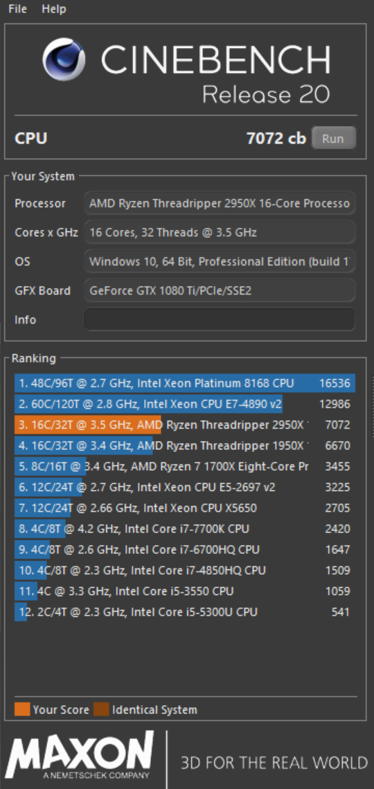
PC life 4 life..... Ryzen 2950x

-
I do not have any right click options for "hid" objects as you do.
-

WISH - Isolate Selected Objects in
MattG posted a question in Wishlist - Feature and Content Requests
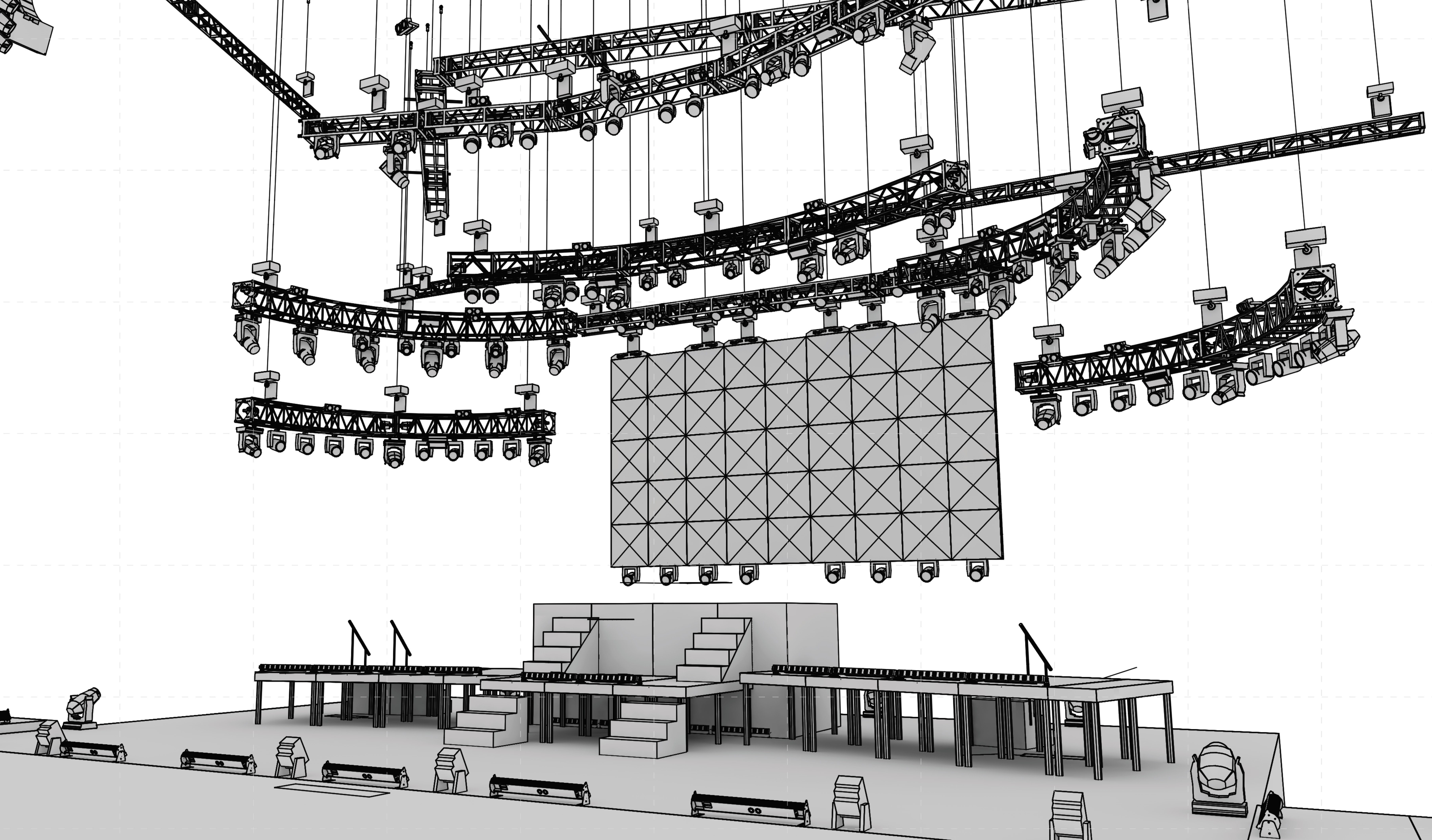
I have had this come up semi-often over the years and always have had little workarounds for it, but I guess I really should have requested this be an option. What I am wanting is a toggle button in the view menu bar that will allow for only seeing selected items. My specific example at the moment is working in the entertainment industry I am working on a lighting system. The system has a number of classes and layers already build. I have a couple of curves that are in tricky places to click and I want to adjust the position of some fixtures in there. I am finding I am selecting non-relevant objects. I am hoping there would be a way I can just select the 10-15 items, click a toggle button, and have only those selected items visible. This is somewhat similar to the clip cube, but in this example, I don't want to try to spend time isolating in on the specific area I am working in I want to focus only on the items I select. I cannot group as items are on different layers and I would lose that, but basically, I want the view like that in the edit mode of a group. Screenshot of current situation attached. Thanks, Matt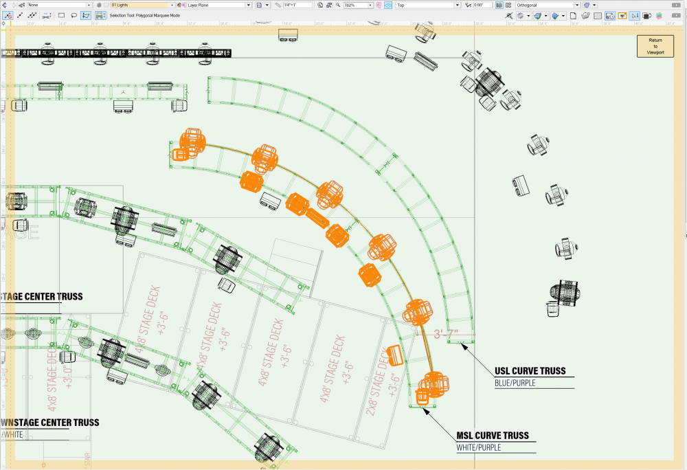
-
This is funny this came up and is active as I am actively trying to figure out a way to do this. I am very much in need of an isolate selection mode at the moment. I think I am personally going to submit a wishlist item for this. Unfortunately things in the drawing are already classed and layered. The item is a curve and the clip cube does not give me the desired results. If I group I give up some of the layering already in place. There really should be a quick toggle to isolate items like in an edit mode, not sure how this is just coming to me now.
-
Section Viewport with turns / interior unwrapped elevation?
MattG replied to MattG's topic in General Discussion
just sent you a message -
Section Viewport with turns / interior unwrapped elevation?
MattG replied to MattG's topic in General Discussion
Yeah they can jog, but not turn if that makes sense so you can have the section line actually go from 8' to say 16' out but not really change direction which is what I am attempting. I wish it was that easy. What I described is a similar example, what I am actually trying to do is significantly more complicated. -
I fear I made a mistake in acting quickly to look at something. I have a file we are working on with project sharing in a shared Dropbox folder. The project file and the working files are in the same directory. I have been just working from my files working file and saving/committing to the project file as needed. I wanted to look at something quickly with a coworker and accidentally opened the project file and didn't catch it. I wasn't actually "working" on stuff in that file we were just chatting about things and moving around in there. However, I did drop in a rectangle just to show something. My issues is I now have the rectangle in my file when I go back to my working file and I am unable to delete it because it is tied to a working file that essentially does not exist. It is the "same" working file I am in. I cannot seem to forcibly check out or do anything to it. I am also the admin of the file. Any thoughts on what I should/could do to get rid of my rouge rectangle?