


jmcewen
-
Posts
112 -
Joined
-
Last visited
Content Type
Profiles
Forums
Events
Articles
Marionette
Store
Everything posted by jmcewen
-
Are they in the same plane?
-
@VIRTUALENVIRONSOf course. attached, but it blew up to 160mb again when I backsaved it. screen shots of the process below as well. It might help enough that you don't need the file. For simplicity sake i assumed symmetry across the miters, but the process should still be sound if it is not symmetrical across the miters. it will just take effort and planning when aligning the nurb path objects for each side so that they meet neatly on the miter line. As another alternative, if this is purely conceptual or visual and not for building printing or cutting, you could array some simple rectangular extrudes instead of the contour step, and then intersect solids with the birail sweep this will be far faster in getting something you can show someone and get the concept approved, but still leave you with geometry you can extract to do the steps above to complete the process for building printing or cutting. see below. The array of rectangle extrusions is actually a singel extrude, so it is not labor intensive at all. Quick and easy. ribbed frame v2022.vwx
-
However, if this is what you are looking for, Chain Extrude is exactly what you need.
-
I forgot to mention, this little file was 160MB before I converted to generic solids. Get rid of that edit history as soon as you feel safe to do so.
-
This might be an oversimplification of your request, but see attached. I think I made a fairly straightforward process, but it will still take lots of repetition if there are a lot of ribs. ribbed frame.vwx
-
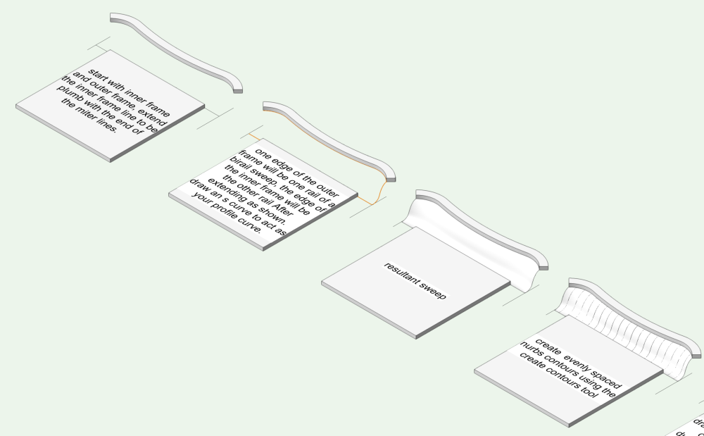
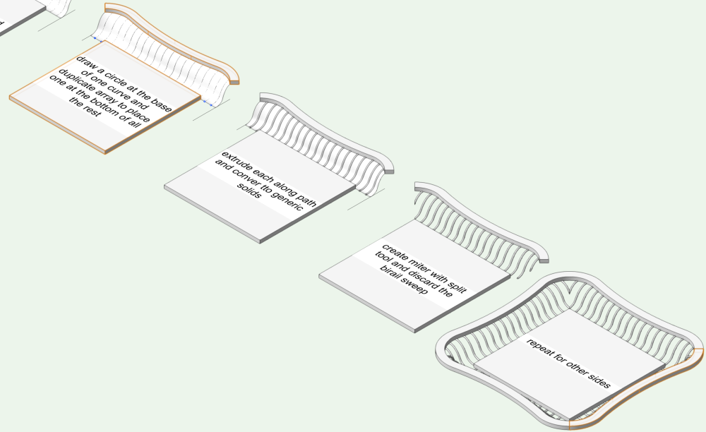
How about this: a birail sweep with the inner frame as the first rail, the outer frame as the second, and then draw your desired s curve for the profile. Then create contours to find evenly spaced s curves, and extrude an appropriately sized circle along each of those s curves paths. Then discard the birail sweep.
-
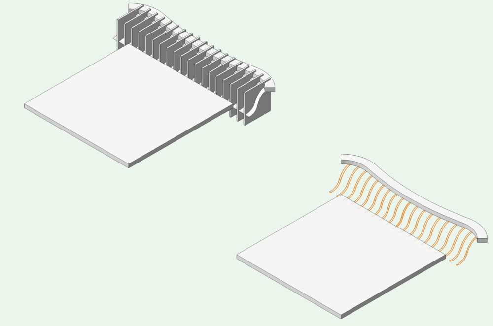
Are you asking how to efficiently make similar ribs of varying sizes once one is made? If they all start in the same plane and end in the same plane then once you create the first rib you can create a symbol of it and scale the symbol asymmetrically. It will technically be a little bit inaccurate because the curves will cause the profile of the ribs to stretch or condense at different rates throughout the path of the curve. If you are just looking for a visual representation rather than something that will be made by a machine this will probably be good enough in most cases. The symbol will make them easy to edit as a batch if you need to revise, and it will keep your file size down-- I am assuming this repeats a lot over the rest of your project. Alternatively you create an extrude along path for 1 rib and duplicate array to place all the rest. Then enter each extrude along path and scale the path object asymmetrically to adjust for the shifting frame profile. This will take longer, but it will be more accurate, and it will not distort the roundness of the rib. The Extrude along Path objects will increase your file size, so once you are sure you don't need to edit them anymore, convert them to generic solids. To anyone with more experience than I have, is there a way to manipulate the chain extrude tool to deal with varying lengths of ribs?
-
Vectorworks Save reminder alert
jmcewen replied to Cadplan Architecture's question in Wishlist - Feature and Content Requests
100% agree, but I also hate that it seems to wait until a critical click to pop up. It would be nice if the save pop-up could happen in the periphery rather than in-focus and preventing further action. Then you could finish your thought before you approve the backup (and then the backup would have one extra click of data saved, too) -
Sweet! I get where you are going. You are making a lot of bits of disparate learning finally connect in my brain. That would have given me greater control over the twisting tentacle as well rather than being at the whim of some algorithm I don't fully understand. Publishing Finals (hopefully) now!
-
Ha! It depends on which 3d tools you mean, and what you mean by comfortable. I have always just picked up what i needed as i needed it. Compared to what i am seeing from you I am not. Mostly I can make things that I think look cool. If I am in charge, I am happy with it because I can choose to work around my limitations to get a project done or I can decide to lean into my limitations to learn more. My problems arise when someone else needs something right now that I can't quite make work. I am almost out of the woods now thanks to the suggestions I have been offered here. Mostly my list is down to personal ego tweaks on the rendering. Thank you for the offer, though, and I might need to take you up on it in the future. Is the twisted ring operation performed mostly with the deform tool? If I were to guess, you twisted 3 cylindrical extrudes, then bent them. I started out with the deform tool on the tentacles. but it failed repeatedly and in unexpected ways. I was not getting any results on the simples deformations, so I abandoned it and decided to try a new path with the extrude along path, and that led to this post. I still need to gain more instinct for how extrude along path moves the profile object around the path object for the future. in some places if i moved a vertex just 1/4", it would induce almost 180 degree rotation about the axis of the tentacle by the time it reached the tip.I also initially had Sucker son the tentacles that i was hoping ot be able to distribute conveniently by duplicating them along the same path object, but they changed orientation in ways that did not match the twists of the extrude along path, even though the settings on the two tools seemed to match as closely as they could. But that is water under the bridge now....
-
Great. this is just what i needed! Both you and @Benson Shaw gave me simple straightforward answers that I should have seen earlier if I wasn't frustrated with the process I had built for myself. That is not at all how i imagined the add vertex on working plane would function. This works a little better in the environment I am struggling in than plotting a new curve with extra vertices to replace the existing curve. I am editing a lot of tapered Extrude Along Path objects, so it helps to not need to completely redraw the object. They are a bunch of tentacles tangled around each other and other things, but I am fighting to keep them from colliding with one another and with objects they are wrapped around but maintaining smooth sinuous lines at the same time. I am under an NDA so I cannot show the whole image, but I got permission to show a detail pic that is small enough that you won't know what it is for. I am an associate designer, and the yellow lines are notes from my boss. You will also see a collision with the tentacle on top of the porthole, and I need to make that tentacle rest on top of the porthole as well. After years of mostly doing breakdown/shop drawings of frames at work it is exciting to be branching into some more satisfying work and getting paid for it! I am happy to have this forum as a resource.

-
This works great for people who know what they are doing, but tends to go horribly when the receiver doesn't know how to use it, and that includes a surprising number of people. I have had recipients tell me that it didn't work, but really they just couldn't figure out how to navigate. It can be a great solution, but consider your audience and be prepared to do a tutorial of how to change views and flyover. I would avoid for use with a typical homeowner or theater director. At this point i primarily use it with people who have access to a modeling program, but are in places where they cannot use it.
-
Thank you. I haven't explored nurbs much before but i am seeing all the processes i was missing before. i like the idea of plotting a new curve on top of the almost-right curve with vertices near where i want to edit. I am pretty sure the deviation will be closer than what I have been get by flinging vertices all over the place currently. Once i develop a little more finesse i will try skipping this new step.
-
When using the reshape tool on a NURBS curve is it possible to add a vertex and slide it along the existing curve to a point near where you want it to end up rather than moving it through 3 dimensions from a vertex that might not be very close at all?
-
I have had mixed results just opening the file in Blender then reexporting a new OBJ. Sometime it works, sometimes it doesn't. In fact, that is the whole reason i downloaded Blender.
-
How many of you use a monitor in portrait mode? I recently started modeling a tall tower and moved my vectorworks screen onto the portrait mode screen that I typically use for editing copy. I wish I had tried this years ago! Now i just switch monitors depending on orientation of the object I am working on-- when I am detailing a column or something like that it goes to the tall monitor. Now I need to put together a slightly modified workspace to change to so I don't need to reposition all my palettes when I switch.
-
What Hardware Does What? - Upgrading your Hardware for Vectorworks
jmcewen commented on PVA - Admin's article in FAQs
I have come back to this post a lot. It has helped tremendously. I appreciate the information on minimum recommendations. I would be interested in knowing when enough is enough though? I am looking at workstations lately fearing that I might need to replace my current machine that is having some hiccups (got a great deal on a refurb, but I think it is starting to show its age.) The post talks about 6 and 8 core CPUs, but there are threadrippers with 64 cores. Is this overkill or a godsend? I model in shaded mode, but present in realistic customs (would move to redshift if displacement mapping, grass and caustics were supported.) Same thing with GPUs. There are a host of GPUs with higher specs than the 6gb recommendation. I am currently not seeing any slowdown on my GPU navigating in Shaded, but if I were to start using Redshift (if more features are implemented) is there any benefit to having loads of vram? Or is clearing the threshold the important thing and anything extra is just... extra? Is anything beyond 12gb just an ego trip and a cash vacuum? Granted, I am digging deeper into some other software now that will also influence my decisions. I am starting to use Blender more, and of course Illustrator and Photoshop-- sometimes having all of them open at the same time. But any recommendations of how much is too much would be beneficial. I want to find enough of a workstation to future proof myself for a little while, but I also don't want to saddle myself with a machine that I need to keep forever because I paid too much chasing specs that don't matter. Also, where do other operations happen, i.e. deform, stitch/trim surfaces, extrude along path, conversion to nurbs or solids, etc. -
Vectorworks 2023 Service Pack 6 Available for Download
jmcewen commented on JuanP's article in Tech Bulletins
It did a similar thing to what happened when I updated to SP5. Progress bar got to 100%, then went past 100% and took away from the left side of the progress bar but only a few percent this time rather than 140%. Then it showed an error, and when I tried to run the update again it said I was up-to-date and already had SP6. Will let you know if I see anything glitchy once I get to use it again. -
We used to do something very similar when I was working with CNC routers all the time. We would make jigsaw-puzzle shaped tabs to lock sheets together when the product was larger than 4'x8'. Once you figure out your tolerances just save the tabs and slots as a resource and drop them in as needed. I always love problems that can be solved once and kept for the future.
-
The deform tool has changed how I do so much of my work. I have only been using it for a couple months, but just learning that it exists has changed my entire style. I find some way to use it on almost everything now.
-
The title pretty much explains it. My dwg imports are super slow now, exports are slow too but not as bad as the imports. I am 45 minutes into waiting on a 30MB dwg to import. I opened my task manager and my CPU usage isn't going above 15% and memory is sitting around 25%. Is there something I need to do in my settings to allow more resource usage after upgrading? Do I just need to revert to 10?
-
3d fillet editability
jmcewen replied to jmcewen's question in Wishlist - Feature and Content Requests
You just made my day!. I had no clue about the right click functionality. This could have saved me so many headaches the past couple weeks! I will need to explore this with some of my backup files to see how it does with some of the silly things I have been drawing lately. I need to figure out how far I can push this before I break it, too. -
3d fillet editability
jmcewen replied to jmcewen's question in Wishlist - Feature and Content Requests
I almost always work from solids, though i am starting to dip my toe into surfaces now that my job has changed. I do too much via subtractions/ and intersections to be able to afford the risk of creating a hollow object early in the process. I have been becoming a lot more organic than I started with lots of deform tool use. Deform tool rarely mattered at my old job, but it is king for me now. Perhaps this is leading to the breakdown you are talking about. But commonly my failure point is when fillets start to run into each other. Sometimes vectorworks will find a way, sometimes it doesn't. When it fails you can give up and try to get there another way, or you can keep filleting other things. Sometimes the later fillets clear the path for the earlier fillet, so go back and try again. about 1/3 of the time after a failure i can reach my goal just by doing my operations in a different order, but I have not necessarily figured out how to predict when the failure will happen based on my geometry. -
I once had the bright idea to generate my bulleted list in word and copy/paste them into Vectorworks. Even that doesn't work. The bullets become a little hand holding a pen instead. Let me know if you find any serviceable workarounds instead of typing them out longhand.
-
I would love to be able to edit individual elements of a fillet by clicking on the individual surface created by the filet 3D fillet tool. Perhaps this could be an additional mode of the fillet tool itself, or perhaps each curve could be selectable when you double click on the fillet object. I commonly have objects that will end up with several filets of different radii incorporated, and It really is only convenient to edit the last fillet you create unless you keep a log of the order of fillet instances. Even repeated double clicking to dive back through the instances in order requires you to go one step farther than the intended fillet to confirm that the fillet you are working on is the one you want. I suspect the potential interaction of one filet element with another fillet element in the same object is why this is not currently available. there are plenty of other tools implemented that fail regularly because the geometry does not agree with the function. There are probably more advanced workflows I should use instead. It is such a quick way to soften things in front of a client until it fails or you need to go back and edit 5 steps before.


