


elc
-
Posts
139 -
Joined
-
Last visited
Content Type
Profiles
Forums
Events
Articles
Marionette
Store
Posts posted by elc
-
-
Hello all,
not sure, if this is a feature request, a bug report or just me being difficult 🙂
Why is it, that I can't use a simple copy paste function in a filtered list /database sub-rows (e.g. filter in 1 and the results in 1.1, 1.2, 1.3,...)
What I want to do is update object data in that list with data from an excel sheet by just copy-pasting values in a range. I can paste values in a single cell and I can paste a range into regular spreadsheets, but not a database spreadsheet. (No mention of it in the help either)Why is that? Will this be fixed?
-
hello,
to save time, I am copy-pasting equipment from room to room or within a room and then bulk-update the device name with the find and replace function.so far so good.
unfortunatelly linked equipment (espcacially rack location, in-rack position and slot number) is not updated accordingly. Updating PIO (Extras>Intelligente Objekte aktualisieren // Tools>Update POI) does not work either. So I have to go to the OIP of each device, change the name to something non existing, confirm and then change it to the correct device/equipment name. ...not really the time-saver I was hoping for. 😉
am I missing something?
thanks,
george
-
52 minutes ago, Nikolay Zhelyazkov said:
So the workaround for now would be to redraw the arrow. We will see what we can do to improve this.
the workaround I am trying to use is to move the object temporarily to the layer of my new circuit destination. move the circuit and then move the object back. But I haven't had time to properly test, if that breaks other connections or misaligns intra-schematic connections. For my current drawings this seems to work. 🙂
(But thanks for looking into it.)
edit: btw. re-drawing is not a real option, as this means losing additional data like cable number, cable type and possibly signal type.44 minutes ago, Conrad Preen said:Just out of interest. On a personal scale of 1 - 10 how would you rate the importance of making this work? Is it worth some loss of performance / slower update?
thanks for asking. again, not a big issue. i'd say 2 since the current workaround above is okay (with 1-"who really cares" to 10-"show stopper") But worth having a look at, I'd say. As that is what ConnectCAD is used for: Drawing devices, circuits and possibly moving them around. 🤷♂️
-
 1
1
-
-
that's the thing. I can't do that. The circuit doesn't recognice the new device on a different layer. (Tried changing layers too.)
Have you tried it yourself? Three devices, three layers moving from one device to another with the move command?
So, is this a bug or a limitation of VW POI?
Thanks,
George
Sorry, not the best screencast. Should have labled the devices etc, but I hope you see the issue anyway.
-
hello,
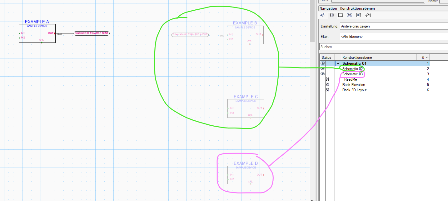
how would I move the connection from device B to input 1 on device D without re-drawing the connection?
from B to C (same layer) works without any problems. To D it doesn't. 🤷♂️thanks for any hints.

-
oh, wow. that looks simple enough but powerful. missed that tool.
thanks! -
1 hour ago, Ben59 said:
is a way to use select similar tool by device name
Hi @Ben59,
as far as I understand you'll have to use "Select similar...">"Record Field" and then Name, Make, Modell or whatever the common denominator is.
sorry, german screenshot, but you get the idea:
(device-Gerät; name-Gerätename; ....)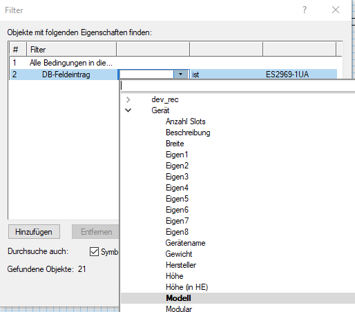
but maybe there is another, less time consuming method? 😉
Is there a way to have "Favorites" or "Presets" when using the "Select Similar" tool? because as I see it one has to repeat the above steps everytime you want to select similar objects as VW does not remember the last settings. 😕-
2
-
-
Hi all,
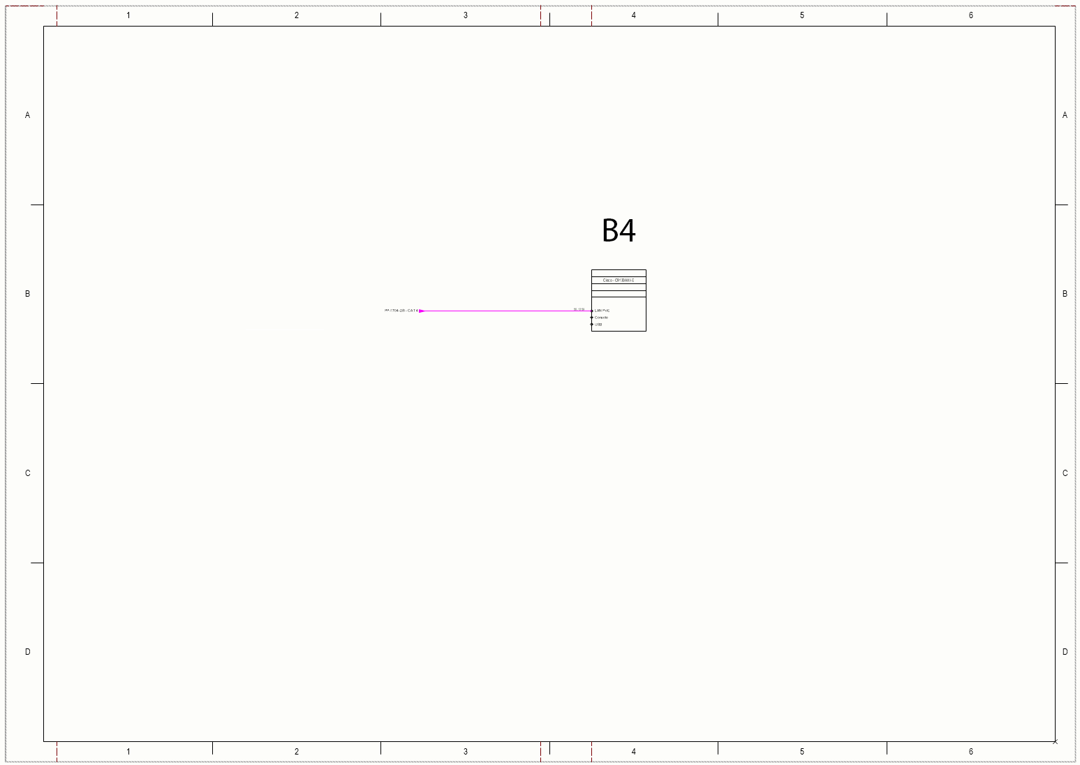
sorry, am at the end of my abilities yet again. We would like to add grid coordinates to our "cable jumps" based on a VW grid reference frame (A-D and 1-6).
So on the other end of the below cable it should say B4 next to the destination device.
Has anybody tried this before? (Imagine this to be useful also for revision clouds etc)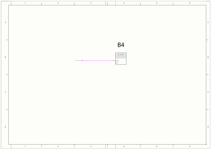
In an ideal world, this info would be automatically added, but since there is no way of linking object data in design layers and layout layers (as far as I know) this is what I would like to try now:
1. Add custom object data to the devices with their location (above B4)
2. write that info to the circuits data (via the data mangager?)
3. reference that data in customized circuit graphics.
My question:
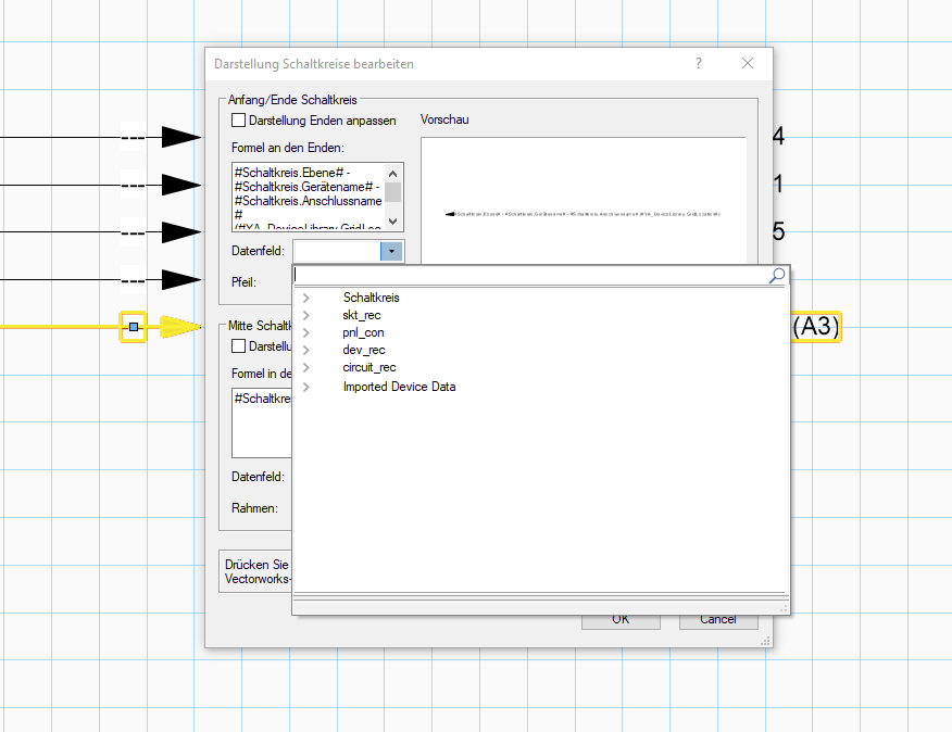
Is there a way to manually distiguish between source and destination data in a circuit object when customizing the circuit graphics?
Since the arrow function seems to differentiate between "source" and "destination" in e.g. #circuit.device# (#Schaltkreis.Gerätename#) as well.
Thanks for any hints.Best,
George
(btw. another idea was to use rooms to automatically locate objects in the grid (rooms A1 to D6). But I didn't get very far as I don't know enough about how to link that info and the above question would come up again.)
-
28 minutes ago, Conrad Preen said:
My suggestions are not workarounds
sorry, was talking about what I currently am trying to do (as stated in my initial post).
28 minutes ago, Conrad Preen said:There is no intention here to force our users into some particular way of designating multi's and their individual cores.
understood. and that is great. but the reason I am using ConnectCAD and dont just draw my schematics in AutoCAD or MS Paint is that I would like to use all those fantastic automations that are already implemented. 😉
And multicores are pretty standard in a multitude of installations. wether it is a permanant installation by AVIT system integrators like us or for a one time event like a Rolling Stones concert. IMHO
that said, there is just not enough documentation and tutorials to learn about this stuff. Luckily my boss is (at least for now) pretty patient with me going through the forum and the available help pages. But also in this case:
Why not incorporate this into a tutorial and offer 3+ ways of presening multicores in a schematic. (ideally with as little manual adjustments as possible)and just to make sure we are on the same page:
I really enjoy working with ConnectCAD and I am very grateful for the features it offers and am excited about the potential it has in combination with Vectorworks for us! ⭐ 😉
edit: and I really appreciate you @Conrad Preen and @Nikolay Zhelyazkov being patient with me (us users) and taking the time to deal with our issues here. 🙂-
1
-
-
49 minutes ago, Conrad Preen said:
Adaptors are on the roadmap !
...yes, good news! and maybe you can squeeze in multicores. 😉
for now I just use the above mentioned work-arounds (as I need to have a cabel number for the individual cables inside the multicore AND the multicore itself. 😕 )
-
Thanks.
Just found another thread on a similar issue (although again, there I have less of an issue with using a device, as it actually is one. 🙂 )and @Conrad Preen seems to have "a new object on [his] roadmap that will represent these adaptors / breakout cables". Maybe multicore cables are included in that thought process? 😉
-
1
-
-
What is the current most elegant way to deal with multicore cables?
All I found was this thread by @tspilman which is not quite the same (although very similar) where there is actually a physical connection point (the OptiCon) in between.
How would I put something like this in a schematic...
(I am thinking about longer cables with e.g. fibres, but this is the longest multicore from the stage-section that I found with a quick search. 😉 )
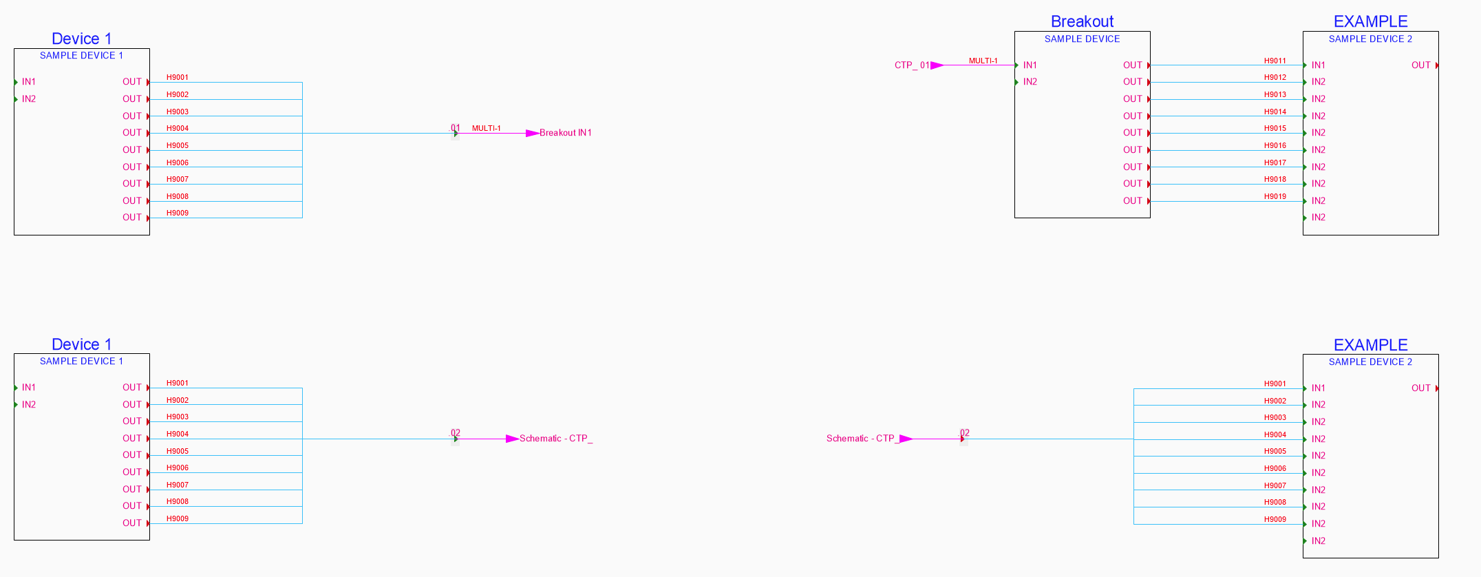
meaning x-amount of cables going though one jacket. each cable might get a cable number (or color-code as above) but the "main" cable might have one too.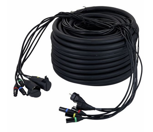
source: the sssnake DMS 222 - 50
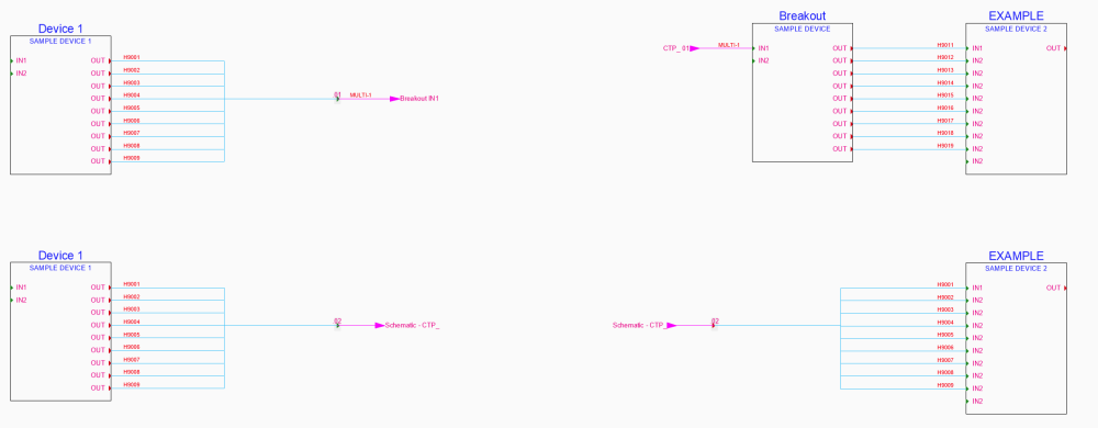
Currently I am trying to use the method above (top) with the multicore being a device (single green arrows), but then obviously on the other (break-out) end, all info on the individual cable numbers/ color codes is lost. And I have to put them in manually. the bottom solution is similar and might be closer to how the snake cable mentioned might be used. (cable numbers on the right side are manually numbered obviously.)
- Does it matter if I use Terminal, Jackfield or connector panel for this? (these are just placeholders anyway, right?)
- How do you guys out there handle this?
- Is there a best-practice @Nikolay Zhelyazkov?
-
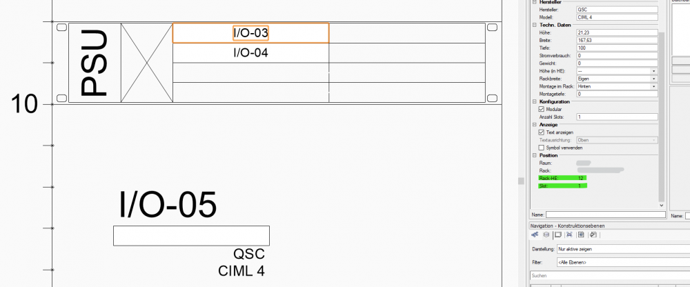
you are right, I won't lose any sleep over this one, just thought/hoped it might be a relatively easy change? 🙂
right now, I show it as 1U device. only real issue I could see is, that when going through the documentation for support at a later stage, I won't see, that in fact we still have half a unit of space for something else in these positi ons. 🤷♂️
but I won't put up a fight over this. 😄
best,
george
PS:
1 hour ago, Conrad Preen said:for the devices they just happen to be using
...going through the images here our device doesn't seem to be some sort of unicorn? 😉
-
Hi @Conrad Preen,
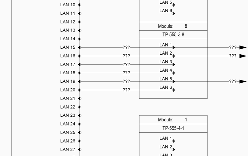
since I am not sure about the way "special devices" like termination and patch panels are used and labeled, I've decided to create regular device blocks for our modular termination panels.
In the example below the device name of the module is e.g. TP-555-3-8 (as I have to give them unique names in order for the rack elevation to locate them, right?)
but what I would like to show is:
when the modules are grouped... I would have TP-555-3 which is the frame name in a device label at the top. and only the module/slot number at the individual module.
when the modules are scattered around the page... i would have the frame number and the slot number underneath.
although I (maybe) can see your point: "why label the frame on the schematic, when it currently isn't labeled in the elevation view", right?
1 hour ago, Conrad Preen said:because there are other ways of doing that
...please elaborate. 🙂
-
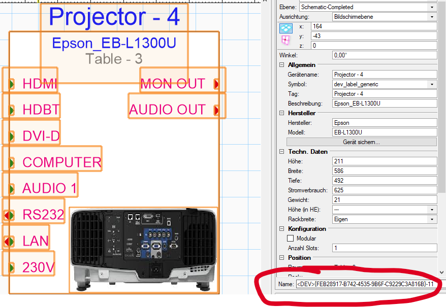
Hi @JimWoodward
thanks for sharing! was actually looking for some hints on how to deal with multicore cables (which you seem to use, but not how I was hoping, you would. 😉 )
What I am very interested in though:
How do you assign those object IDs in the name of an object?Could see anything in the data manager (the only tool me as newbie might expect to be responsible for such trickery.)
Thanks,George
-
Hello all,
really hoping, that by pulling out this "old" thread, I am not poking a hornets nest? 😄
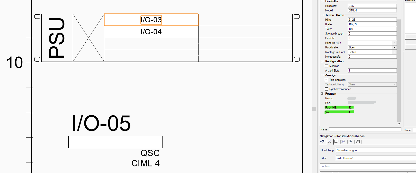
trying to figure out how to efficiently use the modular devices. (really nice feature btw. @Conrad Preen!) I was wondering, if there is any way I can get an info on the rack frame (parent) to my individual cards (children) inside my rack. currently, I can only see Rack and Rack-Position (Rack-HE) of my frame as well as the Slot the card is in, but the frame does not show up anywhere?
what I would like to achive is to have a custom device label of my modules only showing the slot number and the parent device (rack frame object)
PS: I am assuming there have been some changes to the functionality of the rack elevations, as this is probably what your frame looks like today? @ChollyO
-
Would it be a big issue to add the option for 0.5U units to the drop-down of the equipment height as I can't manually change the rack frame height?
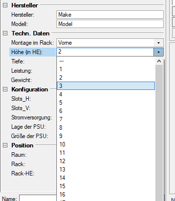
Best,
George
-
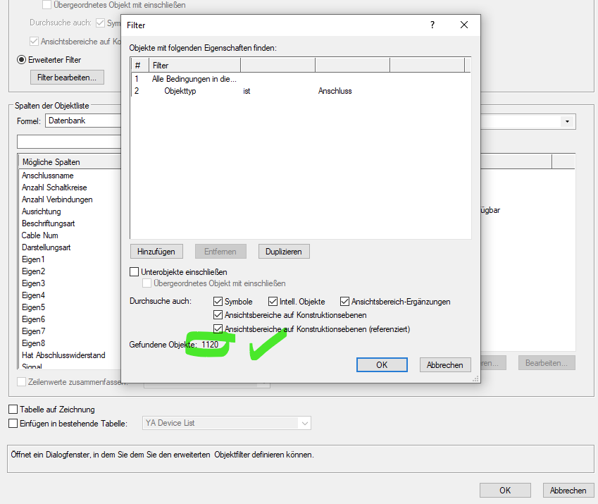
24 minutes ago, Conrad Preen said:
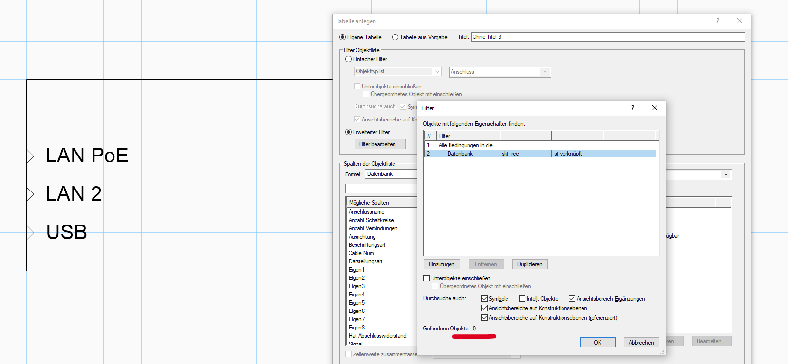
Durchsuche auch Intelligenten Objekte - the sockets are inside devices.
thanks a lot! for whatever reason it worked now.
(or at least I am conviced, that that's what I also tried before. but I might just be delusional.)
but maybe I always ticked "Include subparts" which returns 0 results.
 24 minutes ago, Conrad Preen said:
Also check out these worksheet ObjectData functions to display device data in a socket worksheet
great tip, thanks! works like a charm. was expecting that from ticking "include subparts/include parent object"
but the amount of frustration caused by the translation (whether the german or the english term needs to be used) e.g. in worksheets ... 🙈 -
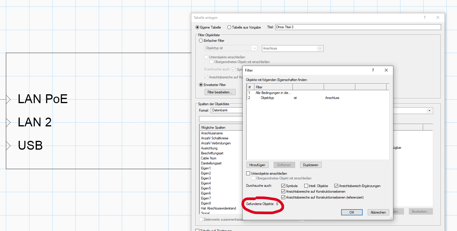
was trying to get a list of all devices in my file, so I could check if they are all up to date with the socket names/count. but whatever worksheet I am trying to create, the PIO "Anschluss" (german for socket) won't show up. But where is their data stored if not in the database "Anschluss"... or skt_rec?

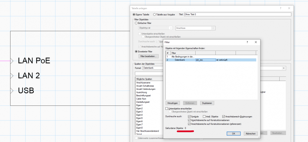
sorry, as I mentioned before, I just don't understand how all the databases and ConnectCAD work together (when I have more time I'll have to create some sort of UML overview of all the depenencies... after learning about how to UML. unless you have something like that already @Conrad Preen 😉 )
best,
george
-
Did exactly that and I get the same error message. 😕
So, guess this is a bug only due to translation issues I hope? Had a similiar issue with the "Create devices from list" tool.
-
for some reason, I can't use the multiconnecttool with patch bays or am I missing something.
Best,
George
-
Trying to use the Create circuits from worksheet, but unfortunately I get an error that the "source and source socket are missing" ("* Quellgerät/Anschluss fehlt"). Not sure, if this is a translation issue, but I can't get it to work neither with the German translation (Quellgerät-Anschluss) nor with the original column names (Src_Dev_Name-Src_Skt_Name)?
1.) Any hints? Or is this one for the german bug-report?
2.) What columns have to have entries for the command to work?
Thanks.Best,
George

-
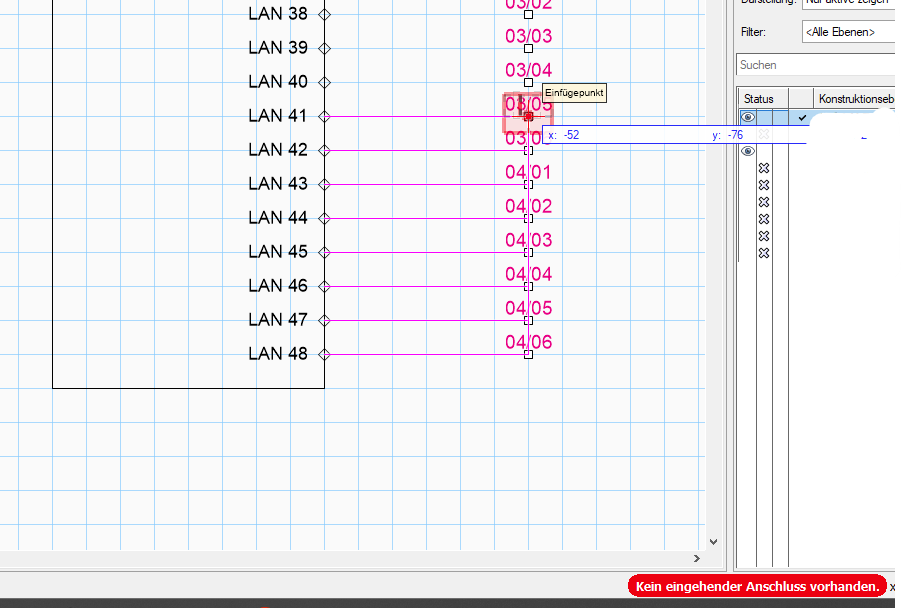
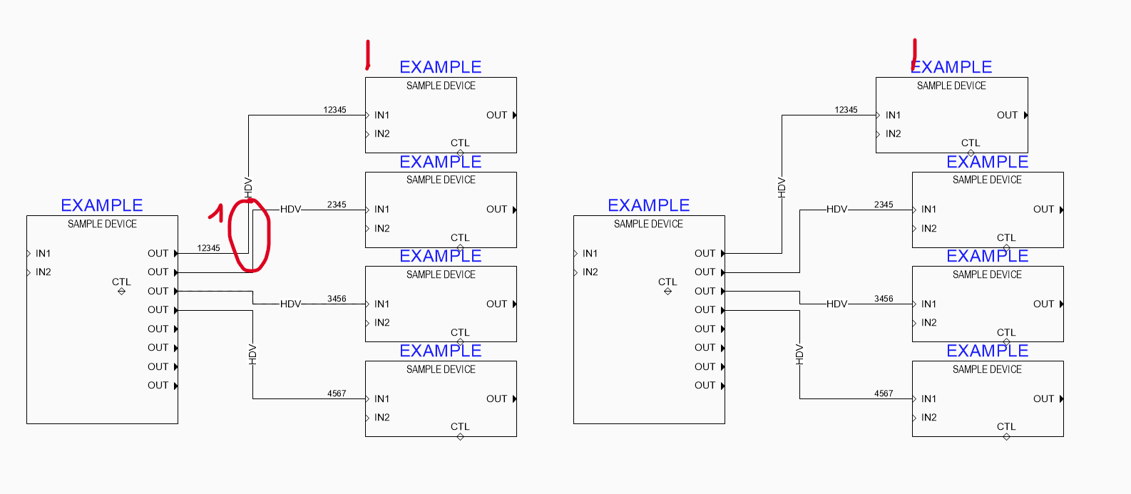
Since I am also just figuring out VW, I took 5min to play around with this and I think I would bet money on the cable length. (and I'm not the gambling type. 🙂 )
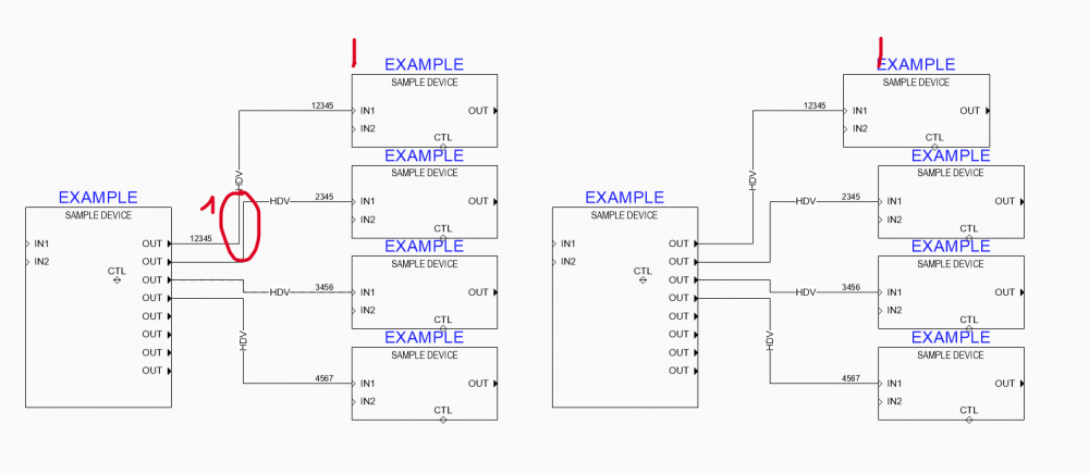
nr 12345 appears depending on the length of the cable. "why have it on both ends, when source and destination are right next to each other" is the logic, I guess. not sure, if this default behaviour can be changed. 🤷♂️
As for your situation: At position 1 you see what I am talking about with spreading out overlapping lines to be able to follow the circuit more easily. You'll have to leave the grid, but it can be done on a dense drawing too. -
Hi @Conrad Preen,
The Version is VW2022 (German) and I am talking mostly about the ConnectCAD Devices DB.txt which I started creating new devices and updating via the text editor as it is a lot faster then the Device Builder in VW.
For example, after having created 30 devices we could then change all LAN port labels from "LAN" to "RJ45". Takes about 30 seconds in the spreadsheet. And adding multiple new devices at once is quite a bit faster too. But I also had to create 15 new signal types as copies of existing ones with a suffix. Which took me 30seconds too.
I was looking for an easier way to reload the file to be able to check my edits more regularly (as I know editing text files can break things. 😉 )
(Thought maybe executing a certain command would automatically require a reload of the DeviceDB.txt for VW)
Best,
George


Copy-Paste data in worksheets/tables not working
in General Discussion
Posted
Thanks a lot @Pat Stanford,
not sure, why I haven't tried that, but copying a range of cells from a worksheet to database subrows does work.
so, that works for me for now. although it is again an extra step to import from excel. so thanks for that bug report! 😉
speaking of strange worksheet behaviours (related as I need to make sure that the cells are in the correct order):
VWs sorting works differently then the "rest" (only tested Excel, Google Table)
it sorts digits in text as numbers...
2404L
3203L
55UH
is sorted as:
55UH
2404L
3203L
which is a problem when copying a range of cells (since I can't sort worksheets with the "VW sorting method", right?)
thanks,
george