


Tom W.
-
Posts
5,016 -
Joined
-
Last visited
Content Type
Profiles
Forums
Events
Articles
Marionette
Store
Posts posted by Tom W.
-
-
8 minutes ago, Carol Reznor said:
When you import a point cloud as is - without centering it on the internal origin as to keep it in its geolocation, you will get a point cloud that is visually corrupted, as in, it will have ugly lines...
Some time ago I reported this as a bug.
This is a massive pain. I submitted a bug about it as well. VB-202892. It's crazy that you have to jump through these kinds of hoops in order to import a point cloud into a georeferenced file.
13 minutes ago, Carol Reznor said:The solution I found for this now is
1. import the geotiff generated by the drone (using the settings of the geotiff - units and EPSG)
then
2. adjust the internal and user origin so they coincide with the midpoint of the geotiff
and finally
3. import the point cloud ticking the box 'Center Import on Internal Origin'
Is Step 4 to Set User Origin to match the Georeferencing coordinate system?
-
 1
1
-
-
1 hour ago, Nikolay Zhelyazkov said:
I suppose that in the other 2 cases mentioned above your text objects have Left alignment selected and not Center, as it is in the rounded rectangle tag.
You are right!
1 hour ago, Nikolay Zhelyazkov said:I think that you have found a bug here caused by the U4 updates to the constraints system. I will log a VB about it and work on its fix.
Thanks for confirming + for filing the bug.
-
1
-
-
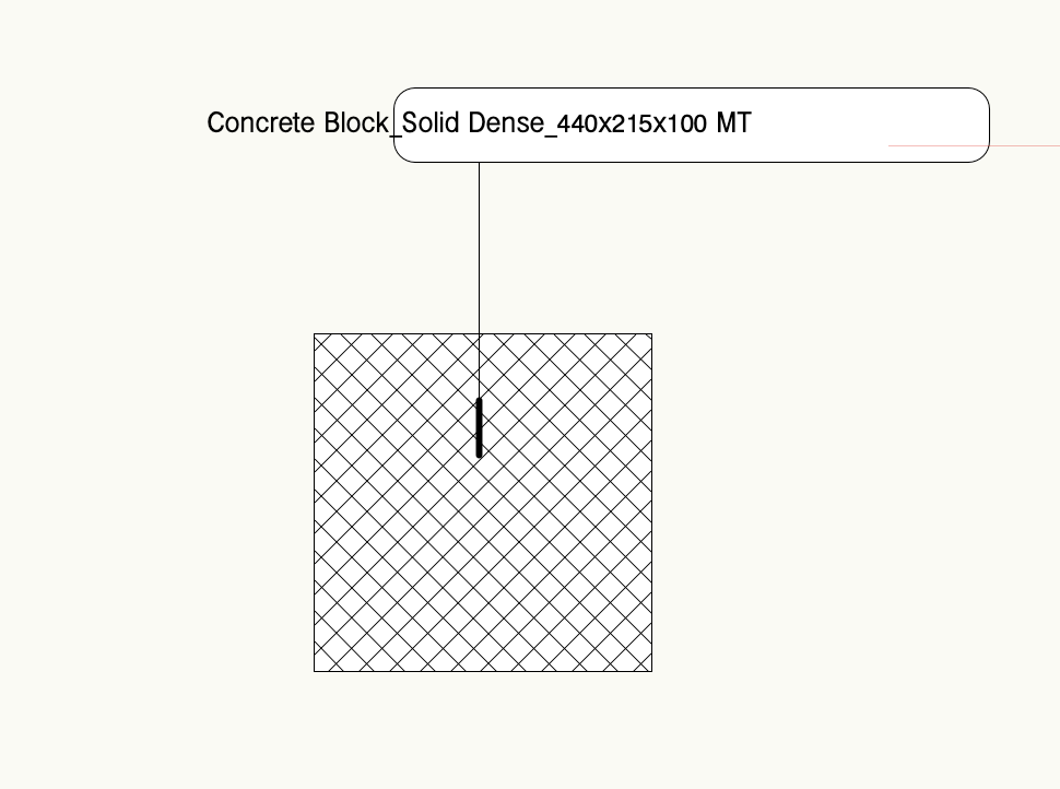
It does feel like per face/per component texturing needs some extra work... Currently you can apply texture overrides + there is nothing in the OIP to tell you you've done so: the only way to check whether the textures you see on the Wall are the style textures or not is to compare what's in the Render tab for the instance with the settings for the style. And the only way to revert to the style textures after applying overrides is to replace the Wall style for those instances with 'Only replace default textures' disabled: 'Remove Texture Override' is greyed-out when you right-click on the parts/component in the OIP. I've been meaning to post VE/VBs for this.
-
Nevertheless @EliM is correct to say that the behaviour has changed in VW2024, no doubt connected to the introduction of per face/per component texturing of Walls. In previous versions the part of the Wall would show the texture being used + allow mapping. So not unreasonable to describe it as a bug...
-
1
-
-
You can attach a Record to a Data Tag then use the 'Link to Data Source' function in the tag to send data that the tag is picking up from the associated object to a Record field which then allows you to colour the tag using Data Vis. If that makes sense... And if I've understood what you want to do correctly...
-
It's something to do with the units. I use millimetres in my files so didn't notice anything untoward. In your file if you change the doc unit to mm it returns the correct value. If you stick with metres but change the decimal precision from .001 to .000001 you will at least see 0.002685 instead of 0.003. Is IFC data in mm by default...? I know nothing about IFC.
Did a quick search + saw this (see Q1):
-
1
-
-
I wholeheartedly agree with this. We sorely need much more control over the edge offsets for Roofs + Roof Faces much the same way we do with Slabs. I posted this a while back:
But I'm not sure if there's an enhancement request out there specific to roof offsets that can be voted for...?
Also not sure what this (in development on Roadmap) encompasses:
-
2
-
-
A variation on @E|FA's suggestion is to try is the legacy Simple Stair Tool (you'll need to find it in the Workspace Editor). With this you can very quickly + easily draw basic stairs then use the Split Tool to taper/splay them, the Deform Tool to bend them, the Push/Pull Tool to create landings, etc. Performing any of these actions will turn them into 3D solids so you will need to convert them in Auto Hybrids or Hybrid Symbols afterwards to regain a Top/Plan representation.
-
3
-
-
2 minutes ago, mike m oz said:
The offset needs to be -20
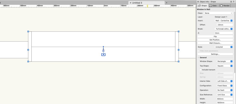
A positive offset should push the Window towards the exterior (left side) of the Wall so it depends on your Wall direction.
-
1
-
-
5 hours ago, Pat Stanford said:
It does seem to be different between VW2023 and VW2024.
What seemed to work for me was to edit the Style and select the rounded rectgangle and choose the Constrain Left and Right options in the OIP.
That should be a one stop fix for all your instances.
I did check the 2023 file and it also did not have the constraints on the rectangle.
So I don't know what is different. Hopefully Nikolay will let us know what we are not seeing.
Thank you Pat I appreciate you looking at it + finding a workaround!
It's strange because other tags where the text is constrained to geometry in the same way work fine i.e. a Line:
and a Rectangle:
So perhaps it's something peculiar about Rounded Rectangles...?
We'll see what Nikolay says!
-
1
-
-
Have just tried to use my Window + Door ID Data Tags for the first time in VW2024 + something fishy's going on.
This is how the Window tag looks normally (VW2023 file):
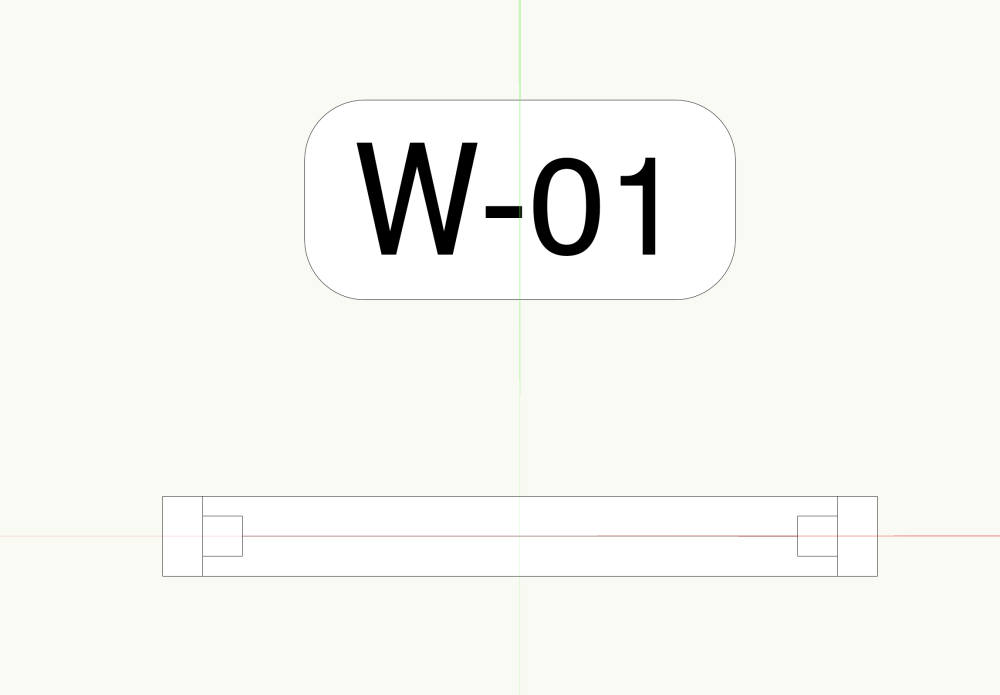
And this is how it looks in VW2024:
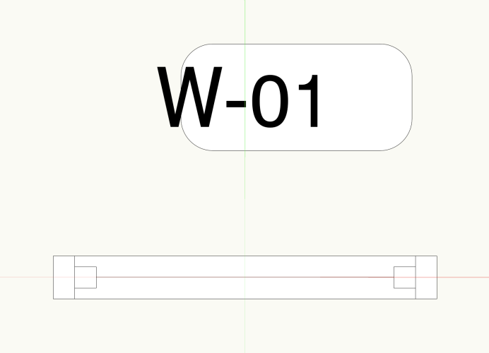
Exactly the same tag, exactly the same settings.
Is this a bug?
Here are the files:
-
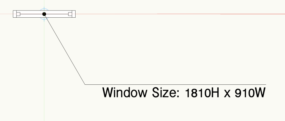
Just apply an offset of 20 in the OIP or Plug-in Object Options (or in the Plug-in Object Style Options if it's a styled Window + these settings are greyed-out).
-
1
-
-
1 hour ago, hollister design Studio said:
Right clicking is fine... but having access to ALL information from the "information" palette just seems like a good idea.
I guess because right-clicking is how you already access the Plug-in Object Options, having an additional 'Plug-in Object Style Options...' choice here seems the most logical thing to do, but I've no objection to a button in the OIP as well: the more ways to get to these settings the better really!
At the moment I right-click on the object, select 'Locate Plug-in Style in Resource Manager', right-click on the resource, select 'Plug-in Object Style Options'... That's a lot of clicking!
-
4
-
-
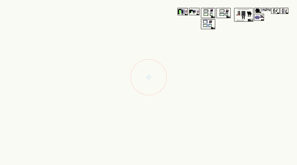
8 hours ago, Jeff Prince said:
Vectorworks has never explained why, but I found the "5km safe zone" does not apply if you have geometry at the origin. I've had site models over 50 miles across without issue, as long as they are centered on the origin.
Yes I remember this. You could perhaps understand if it was a single Site Model 50 miles wide centred on the IO but I think in your case it was multiple DTMs abutting each other...? So does that mean you can start drawing your geometry at the IO + build it outwards to a point 50 miles from the IO + all will be fine...? It's only if all the geometry exists outside of the 5km safe working zone that you will have problems? I've never had a model bigger than a km across so haven't had an opportunity to test this 🙂
-
See:
and:
-
2
-
-
5 hours ago, hollister design Studio said:
Two years later and I just had to search for this post again.
It really makes no sense to me that this setting is not on the 'edit style' menu.
Shouldn't BOTH the "Edit Style/Landscape area Style" menu and the "Plug-in Object Style Options" menu be accessible from the OIP?
...especially as you can't right click on a landscape style and open it directly in the resource menu, you have to search for it.
This is common to all PIOs (+ symbols) + has been the subject of much discussion. Others have requested the same as you (assess PIO Style Options from OIP) whilst I'd be happy right-clicking on an object (in the drawing) + accessing them. @Matt Panzer said it was under consideration but not sure what the latest is... Do a search + i think there are wishlist items for this.
-
4
-
-
34 minutes ago, line-weight said:
so I'm not sure what the benefit would be in making it something separate.
I’m not saying it would be beneficial, I just meant from a practical/engineering point of view: what we could reasonably expect VW to achieve. But I have no idea how hard or easy it would be. Perhaps someone like @Matt Panzer could comment…? After all, standard walls + curtain walls are two distinct tools because they operate in completely different ways + it strikes me that we’re asking for a single tool that does both things (which might be a tall order). -
Also, check the scale of the objects. Everything is rather large. The red circle is your 5km safe working zone around the Internal Origin. The geometry fills the screen:
-
1
-
-
2 minutes ago, line-weight said:
I was actually referring to your more general comment about whether a way of setting out framing should be tied into to the wall tool.
It would be great if it was of course. I'm only thinking that walls come in many different types + only a proportion of them are timber framed + even then you wouldn't necessarily always want to model the framing. Maybe it would need to be a completely separate wall type: so 'Standard Wall', 'Curtain Wall', 'Timber Framed Wall'....?
The plug in that @Ryan Russell referenced was just for framing - in fact just for roof framing as far as I could tell.
-
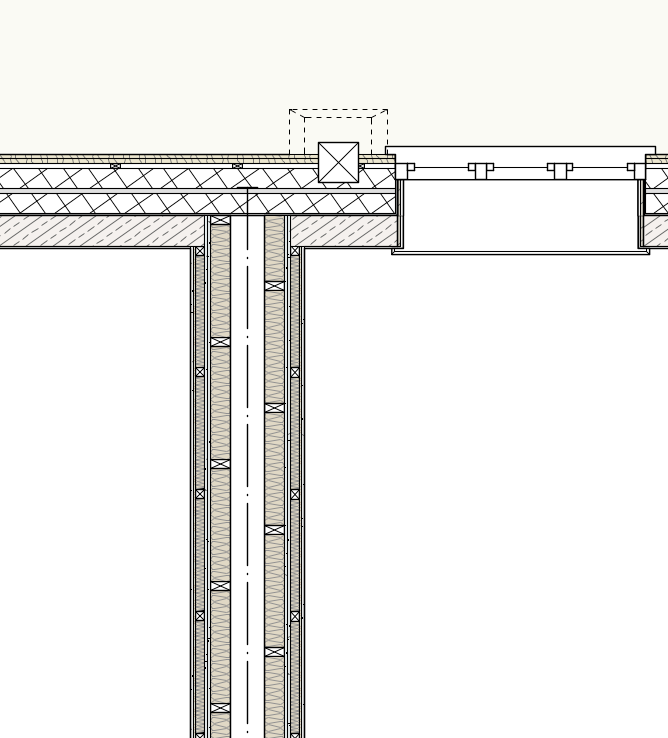
6 minutes ago, line-weight said:
Seems to me like it would be quite important that if you changed the line of your wall, the framing would update along with it. And the wall object already defines the plane and thickness and so on.
The Tile rotates with the Wall if that's what you mean. That's not an issue. The issue is things like this:
This is the Wall drawn initially, with the studs + battens aligned as they would be in reality (the Tile geometry has the same origin):
But once the Wall components are offset (at the Wall join) you lose the alignment:
The other thing to bear in mind is that this is all fine in a Top/Plan view but in a vertical section you obviously don't want to see the studs, you just want to see insulation, so this requires a Data Vis be applied in those VPs to change the fill.
8 minutes ago, line-weight said:(haven't tried tile fills for that purpose by the way; I should investigate)
The other thing I do is show UFH pipework in screed (in Slabs) which is quite useful.
-
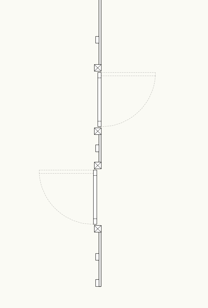
10 minutes ago, line-weight said:
It would be nice to have some kind of automated 2d representation (in plan and section) of timber framing within any component of a wall object that is in fact timber studs plus infill rather than a continuous material.
I do this with Tile Fills but you have no control over where the stud/battens appear so it's purely indicative + arguably not that helpful:
If I want it done properly I use my hybrid framing symbols mentioned earlier.
But I agree that it would be nice to have a better solution, although not sure if tying it into the Wall tool is the way to go
-
1
-
-
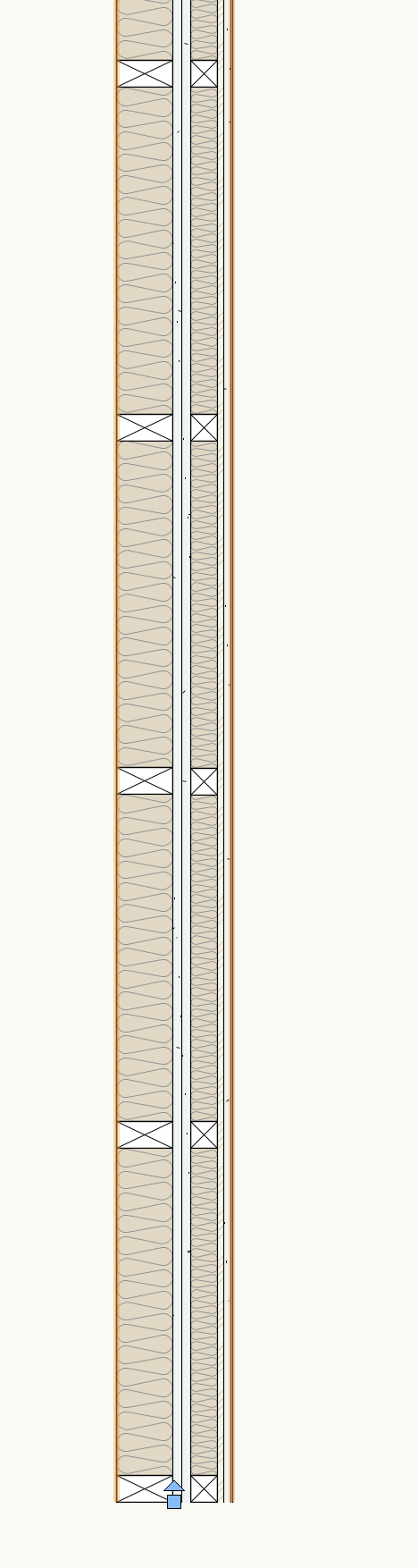
1 hour ago, Byggdesigner said:
In my case, we work in 99% with Paroc Sandwich elements as outer walls, as in attached image, for warehouses etc.
And only on a mezzanine plan with inner walls directly to this in the office area.
Just because I can 🙂 I usually draw this like "a room inside a room" in Revit, where its easy to join the outer walls and place windows and doors, but still have the walls as two seperate. Testing VW out and this was the first headache 😉

Might be better to have two different Wall Styles: one for the unlined walls + another for the lined walls where they occur
-
3
-
-
You need to add 3D Loci to the gate symbol. See attached. You basically do something like measure the distance from the centre line of the Fence to the outermost point on the gate (i.e. the latch symbol) then times this by two + that's the distance the loci need to be from the front of the latch. At least I think that's right...
I didn't do anything with the gate posts as I wasn't sure what you were looking for there.
This is one of my fences:
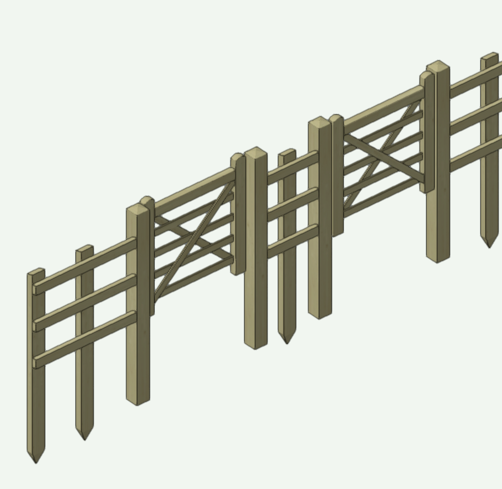
The gate works fine when first inserted but the offset is wrong when flipped across the fence... Something to bear in mind.
-
Can't vouch for @Byggdesigner but parallel Walls is a common workflow for renovation projects where you represent the existing architecture with one Wall then the proposed wall lining with another. This makes it very easy to switch between the existing + proposed models in Saved Views + Viewports + means you can freely make changes to the proposed architecture without risking affecting the existing architecture.
-
2
-


Worksheet Function in Data Visualization
in General Discussion
Posted
Can you post a simple file with an object + a tag? One thing I'd say is that you don't need 'Link to calculated/user-entered field' to be checked, only 'Link to data source'.
Also, from your first post I thought you were looking for a way to use Data Vis to colour your tags based on field data from the tagged object. This requires a dedicated Record be attached to the Data Tag the sole purpose of which is to allow you to colour the tag itself. So you take data attached to the tagged object + send it to the Record attached to the Data Tag. In your screenshot you are sending the data back to the object. Which is fine but not what I thought you were trying to do...