


Conrad Preen
-
Posts
1,023 -
Joined
-
Last visited
Content Type
Profiles
Forums
Events
Articles
Marionette
Store
Posts posted by Conrad Preen
-
-
Hi @jdepaepe
Can you help me out a bit? I'm struggling with the terminology you are using. Let's use the actual names of ConnectCAD objects i.e. Device, Equipment Item, Rack, Rack Frame etc.
Best wishes for 2021.
Conrad
-
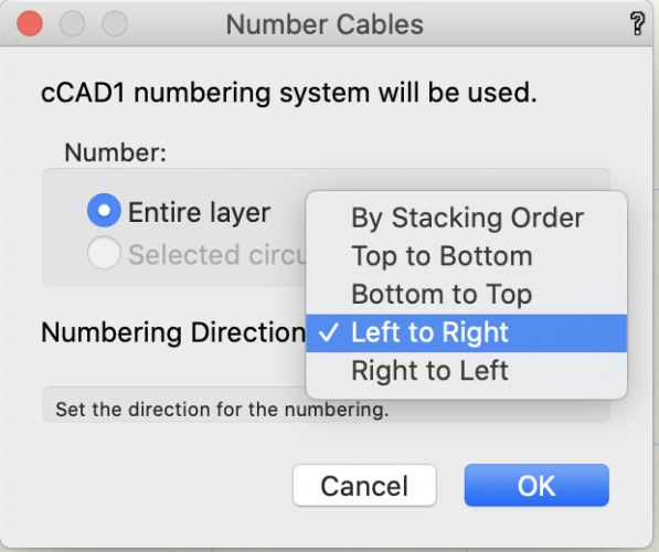
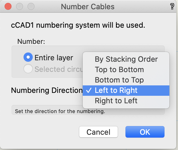
@mark4 do feel free to try values other than 1. My point was only the setting 20 grid spaces was causing the issue you reported.
Happy holidays!
Conrad
-
-
It's not possible to turn off the text in the current version. It is something we could consider. Would you be wanting to turn off the text for all Equipment Items at once or be able to intervene in individual objects? Not promising you anything here. The point of ConnectCAD is to automate the drawing process and save you time. If we keep on adding extra tweaks we expose more and more complexity to the user and defeat the object.
If you want to produce a version of the rack drawing for presentation why don't you just select the objects and go Modify > Convert to Group? Then you can go in and change the text to whatever you need. Do this on a copy of your original drawing and you keep the ConnectCAD rack drawing in case there are any changes.
If you find yourself doing the same operations regularly, why not get into Marionette and put together a neat little script to shuffle things around the way you want? What I'm getting at here is that Vectorworks has the tools.
All the best for Christmas and the New Year
Conrad
-
Hi @Luther Core
You can find some blank panels in the Default Content. Use the Resource Manager to browse to Objects - ConnectCAD. I usually recommend using the Rack Frame Object to model rack shelves since Equipment can then fit nicely to the slots when you drag-drop it in. Double-clicking the Equipment Item object opens its internal group. You can add your own graphics in there to enrich the look. A great way to do this is to paste in pngs clipped off manufacturers websites.
Hope that helps.
Best wishes for Christmas and the New Year,
Conrad
-
Hi @mark4
Thanks for sending me the file - now I see the problem. You need to check ConnectCAD settings. The offsets for Circuit Labels (General tab) have been set to 20 grid spaces. So ConnectCAD is dutifully putting the connector type and the circuit number 20 grid away from the socket. Set these to 1 grid and things will look a lot nicer.
Best wishes for Christmas and the New Year
Conrad
-
Hi @mark4
The minimum length of arrows is controlled by the snap grid setting. So the minimum length is 3 x snap grid + the size of the arrow marker on the end. Unless you have a special reason not to I would always suggest to begin from the standard template and branch out from there.
The sizing and spacing of schematic objects is controlled by the snap grid first because it helps keep things on the grid which looks better, and secondly because that allows you to draw schematics on to-scale drawings such as floor plans using a larger snap grid so that schematic elements look sensible.
Hope that helps. If not please PM me the file in question.
Conrad
-
@livespace josha just trying that here following your steps and I can't reproduce the problem yet. So I'll definitely need that file.
-
Hi @livespace josha,
Can you PM me a file that shows this? I need to get an exact idea of what's happening.
Conrad
-
Hi Neil,
Well it's great to have somebody "pushing the envelope"!!! Certainly the case with arrow connections was picked up by our testers and noted. I would be the first to support the idea of allowing you to restructure your drawings at will by adding layers etc. But for some things it's easier if you set hings up from the start. I think that as you gain experience with ConnectCAD you get to know how to read the road ahead a little better.
Thank you as ever for posting these observations. We always take note and if we can fix we will.
Best regards
Conrad
-
Hi Neil,
I'm not sure I get the concept of separate rack elevation drawings for audio, video etc. Why do this? Maybe if you PM me the drawing it will make more sense to me?
Conrad
-
Hello @sbecraft
To clarify this for me could you PM me a sample file and the steps to show the problem?
Conrad
-
Hi Neil
Yes I know this is the case. Any particular reason why you need this workflow - just as a matter of interest?
By the way if you select the circuits and nudge them (Shift-Arrow) the reset and re-detect their devices.
Conrad
-
No need to apologise Ryan! Glad we can help!
Conrad
-
Hi Neil,
I wouldn't expect an equipment item to "know" that it is in a room placed on another layer. How people decide to use layers varies a lot. Surprisingly I discovered recently that Layout Room objects and Equipment play nicely together even when working in 3D. The room can only be a rectangle (right now) but it can pass its ID to equipment (on the same layer) placed inside its XY bounding box. Which might be good to know...
Conrad
-
Hey Neil,
I began writing up the case for a Text Wrap checkbox and I had a thought...
Seems to me that we should wrap the text when it is displayed within the Equipment boundary i.e. Left, Center, Right but it should not be wrapped when displayed Above. That way it will "just work" without extra controls. What do you think? Would that fix your issues?
Conrad
-
Thanks Neil,
A picture is worth a thousand words. I'll go ponder this one a bit more.
Conrad
-
Hi Ryan,
Not sure I understand you. In ConnectCAD 2021 we give you all these choices. What doesn't work for you?
Conrad
-
Hi Neil,
That's not a bug but our attempt to make this object just work regardless of what you do. The name display is prioritised over the Make and Model. In general I think it's preferable to avoid adding a miasma of tweaks and settings to a piece of software and instead put the complexity inside the software. If we can cover 98% of use cases I reckon we've done a good job. Adding extra controls to cover the remaining 2% comes at a heavy price - the software becomes incomprehensible for new users!
When you consider the cognitive load imposed on people by the sum total of the software they use, it makes every bit of sense to do our best to relieve this.
Conrad
-
Well suppose you wanted to add some extra connectors on your panel that weren't in the schematic? You could grab the connector symbol from Default Content but you would want to set the name.
Or supposing you had saved a pre-built panel as a symbol and dragged it in, and then you wanted to manually assign the connectors to match the ones on your schematic?
Just two cases off the top of my head.
Conrad
-
Hi Neil,
Thanks for the feedback. Some tweaks to this workflow have been on my list for a while now. We'll take a look at that.
Conrad
-
 1
1
-
-
Well changing the schematic socket name this way wasn't really a workflow that I had in mind. And it really begs the question in my mind as to whether that's what you would want to do every time? Changing stuff automatically on another layer that you can't see falls under the heading of "unforeseen consequences" in my book. We should definitely be very cautious about that.
My 2c worth.
Conrad
-
-
@Kelzilla1000Thanks for the heads-up! It may well be that the Germans have localised the folder to Geraete Symbole or something like that. You can track this down in the default content - the English path to the file is /Libraries/Defaults/ConnectCAD/Device/Device\ Labels.vwx. You should be able to burrow down into there in the Resource Manager ( Zubehor Manager? ). Sorry but it's been a while since I had dealings with the German version and I don't remember all the translations.
Give that a try and let me know how it goes. If you can't find the answer I'll ask Computerworks.
Conrad
Rack Accessories & Design
in ConnectCAD
Posted
@Luther Core I just tried out the blank panels and they are working fine for me. Could you expand on what you mean by "unusable"? By all means send me a movie or sample file so I can see what's going on.
Best wishes for the New Year
Conrad