


Luther Core
-
Posts
8 -
Joined
-
Last visited
-
Thanks Nikolay, I'll play around with scaling as the default size is far too large when the drawing is scaled at 1/4. Regarding the Libraries let me verify if it's stored in the correct location and I'll follow up with you.
-
Is it possible to scale the size of the drop point symbols installed using the new drop point tool? I haven't found a way to do this. Re-sizing the drawing is equally problematic. Where would this new Drop Point be located? I created a new folder based on the other thread. It creates a folder in the document, but I need it as a library for reuse. The previous User library I created is in the list, but not accessible via the Drop Point tool. This is the thread I referenced: All help is welcome. Thanks!
-
I think it partially depends on what's in the tool. Netzoom has a team of people that create the stencils. The turn around time is usually couple of days which is EXCELLENT. This is not just for the visuals but ALL of the connection points as well. The data portion is similar to ConnectCad where you add in weight, power manually. The last time I used them I believe they charged around $700 per year which I felt was high relative, to what you got as it relates to Vectorworks/ACad/Bricscad etc. To be honest, for the cost of Spotlight + ConnectCad and the fact that most of the functionality is already available, I feel it should be included already (w/caveats). Your additional $250-300 feels reasonable. I would consider paying more for the device to have full information included: dimensions, weight, power, btu's, but I don't know if it's worth the extra effort on VW's part especially since some manufacturers don't readily provide this info. Would the tool allow the importation of cad blocks directly from manufacturers (this we can already do it's just not a part of Device Builder)? Would it include an editor to allow the complete creation of the block if not available from the manufacturer (This we can sort of do via Panel Builder but the panels would need to be attached to the device)? Since most of the tool is already in Vectorworks, they'd need to make the business case for modifying the software design so Device Builder and Panel Builder are more integrated and make the business for creating accurate symbols in house and including them in the library. My take is it should be VW provided and community based. If VW provided, each device needs to be as close to perfect as possible. If community based what becomes available should be as-is. This means if I create something that is incomplete, VW has NO responsibility to fix it and we use at our own risk. VW blocks should be labeled as such so we know they are complete and Community blocks should be labeled as such and each creator should state the level of completion, notating what is missing. From there it would be excellent if there were a means for VW and/or the community to update the device and the level of completion. VW would only need to verify that it is correct before receiving their stamp of approval to it's level of accuracy.
-
Happy New Year, @Conrad Preen, Please see the attached video. I hope it's something I am doing wrong but no matter whether the drawing is in 2D Top/Plan mode or isometric, the rack panel/equipment never allows me to release on to the drawing (even when selecting an insertion/endpoint. It stays attached to the cursor. Also, ConnectCAD does not show up under Symbol Insertion/Vectorworks Libraries. It only shows up under Resource Manager/Vectorworks Libraries/Objects - ConnectCAD. Regarding jdapaepe's request. For me, in a perfect world when you create a new device using Device Builder there would be an option to add an image. Ideally, this would be the Equipment Image which would then also be used for the Device if desired (check box?). Obviously, everyone has a different workflow so maintaining the ability to have a different image for the Equipment or Device is desirable. Maybe the "Device Builder" would change to the "Equipment Builder" since equipment encompasses the device as you stated in your earlier reply. Screen Recording 2021-01-04 at 1.11.16 PM.mov
-
@Conrad Preen I'm not sure if this is a bug or not but when I drag the blank rack panel into the drawing it is unusable. Other resources can be used with no problem. When I bring in the rack panel, insertion point and endpoint options show up but when selected they do nothing. The rack panel does not insert into the drawing nor does it anchor to the insertion / endpoints. Using the rack frame as a rack shelf worked well. Thanks
-
Thanks @Conrad Preen I am going to try this right now. Wishing you a great Christmas & New Year. Luther
-
Is there a preferred method for adding accessories to a rack in order to show the rack in it's complete form? For example, I tried using device builder to create a new device with NO I/O's in order to have a "dumb" rack blank or shelf. It created the device, but the device would not snap to the rack. I also tried to create a "connector Panel" with no connectors. That didn't work either. All of the correct devices are in the rack but the blank panels, vents, shelves (for non rack mount equipment) and drawers do not exist. Also, the addition of bases with casters could be useful Is there a quick way to add device images to the "face" of the rack device to mimic rack designs such as that created by NetZoom? See attached pics. It would be great if there was an image field so line drawings or jpg, png etc images of devices could be added. This could be in the device builder or in the Object Info/Display area.
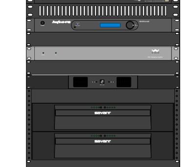
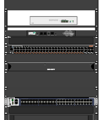
.thumb.jpeg.da9e05fe686825d8a2064118a858dbf5.jpeg)
-
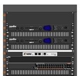
What is the best way to save symbols in device builder? Currently I have device on a design layer that I needed to copy from a previous drawing. The previous devices were saved in a User Defined generic library. Unfortunately after making changes to the connectors and signals txt files ConnectCad would no longer work (it would hang while opening the drawing file or would hang while trying to create a new ConnectCad document). The repair tool did not work and ConnectCad continued to hang. The drawing file worked fine on tech support machine. Tech Support, recommended uninstalling and re-installing the program. Of course, everything in the User Library was deleted. Opening the original file included my original devices. When I choose to "Save as Symbol", I receive an error message "The symbol [insert name] already exists. Do you want to overwrite its content?". Choosing ok does nothing. The device is NOT created in the Device Library. Even changing the device Make and Model does not result in a new device being created in the library.


.jpeg.df483e9ef82c4f89824f036d2165f7b8.jpeg)
