Conrad Preen
-
Posts
1,062 -
Joined
-
Last visited
Content Type
Profiles
Forums
Events
Articles
Marionette
Store
Everything posted by Conrad Preen
-
@GoodDesigns We have good reasons for wanting to retain ownership of the taxonomy. These include the fact that Vectorworks is localised into several languages. So regarding your wish. Message received - we will include a new category for security. Inevitably the taxonomy is imperfect because items for example like cameras may be used for security but also for video production. But at least it gives you a way to narrow things down. We have a major overhaul of device content in the pipeline so we can include the new category in there. Thanks for reaching out Conrad
-
Hi @rjoshuar There isn't a command that does this. However, it is quite easy to do in Vectorscript. If you are interested in having a go check out https://developer.vectorworks.net where you can find the function reference together with various examples. Conrad
-
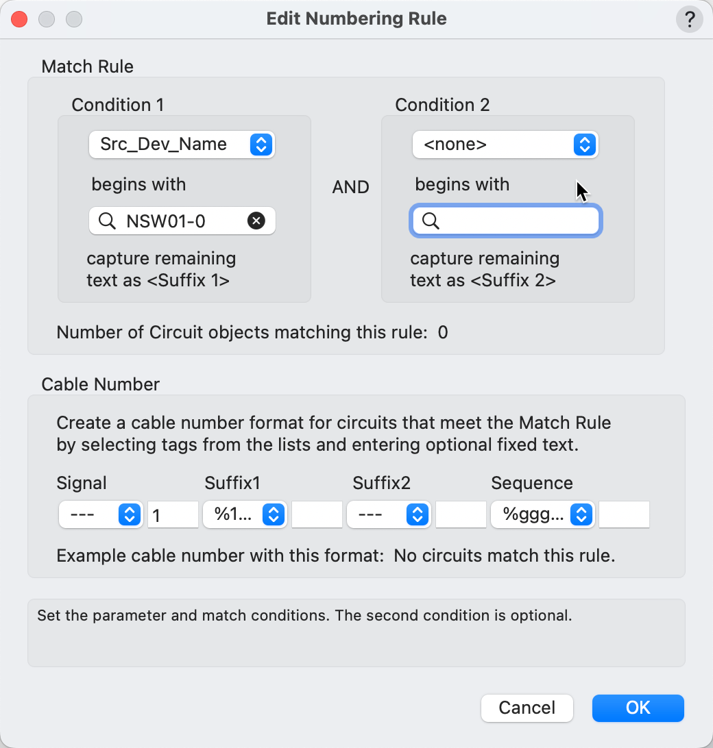
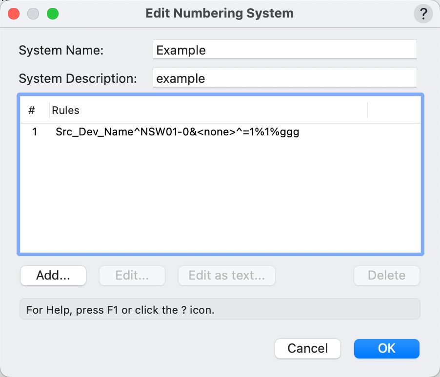
Hi @AudioEngiNerd Have a look at how this sample numbering system works. We look for device names with a prefix that indicated a patch panel and grab the suffix to be part of the circuit number. All this is quite well explained in the online help. Conrad
-
So the source device name has to match the prefix NSW01-0 and grab the suffix 1 or 2 as the case may be, and the cable numbers matching these criteria will be the suffix + a 3-digit incrementing number - correct? So, if I understood correctly this should get you what you want. Conrad

-
You could do the same with a Data Tag too.
-
@tom-SPL Well that doesn’t need any special programming. You can make a worksheet report of your racks listing the power consumption for each rack. In another column divide the power by the voltage to get the current, then divide that by 20 and round up to the nearest integer to get the number of feeds needed.
-
Hi @tom-SPL "generally useless" ??? well respectfully, that's just like your opinion man...! Many people find it very useful to know the power consumption of a rack. Each equipment item in a rack each has a power consumption and that's what we add up. Converting that to current consumption involves knowing the voltage of the power supply. This varies according to which country the installation is in. I think the best solution for you is to use a Data Tag that will do the calculation. The formula you need is Amps = Watts / Volts. That would give you the total Amperage. Regarding your other points, I'm not clear exactly what you mean by this or Send me a picture of what you want and I'll see what I can come up. Conrad
-
Devices and Circuits Appearing 3 Times on Reports
Conrad Preen replied to Ian5100's topic in ConnectCAD
Dear @Ian5100 Would you be able to share here or PM me the file in question? For any problem, the first step on our road to helping you solve it is to be able to reproduce it here. So the more information you provide the faster we get to this first stage. Ideally in general we would like to know: What you were doing when the problem happened. What you expected to happen. What actually happened. What version of Vectorworks you are running including the build number. What platform you are using (Mac, Windows) and what version. An example file that's shows the problem and the steps required to make it happen. Screen shots or videos are also very helpful. I completely appreciate that it isn't always possible or even necessary to supply all of these, but the more you give us the sooner we will be able to help you. Any customer-supplied files are treated in Vectorworks as highly confidential and we will only use them to diagnose the issue. At the moment I know that you are running VW2024 and that you are seeing multiple entries for Devices and Circuits. Looking forward to hearing from you soon. Conrad -
@Pat Stanford Thanks for the input Pat! I still think that the rack frame is a good starting point. It will need slightly different fit-to-slot behavior and locations will have to designated ordinally from left to right. That creates a bit of a hassle in that if you want to insert a module in the middle the locations of all the modules to the right of it need their slot numbers incrementing. And we need to think about empty spaces in the middle too. But we can stretch the model a bit more to fit all this. No promises for when. Conrad
-
@Pat Stanford Isn't it true that DIN rails use a standard module width of 18mm? In ConnectCAD you can specify the number of slots occupied by an equipment item. So on that level I think the rack-frame is a possible starting point. @spettitt regarding 2D vs 3D, I think there is no question. We've gone 3D with all our equipment layout and we're not going back. Anything that is required to make 3D as easy to use as 2D is definitely on the map. As for the link between DIN rail devices and modular equipment in a DIN-rail-style rack-frame, this pretty much comes for free since we'd be leveraging the existing model. Regarding circuits as signals vs. cores yes there's a kind of ambiguity but it's a good ambiguity because you can use it! ConnectCAD keeps track what's connected to what and leaves it up to you to decide on the interpretation. It's very easy to add complexity to software and very hard to get rid of it once it's there. So unless I can see a very clear path to a deeper level of detail in the general sense I think it's better to leave it as is. Conrad
-
The thing is that the symbols used internally in sockets and device labels are scaled according to the snap grid at the time of import. But the text drawn by Circuits is scaled according the current snap grid. So if you change the snap grid in mid design then this can give unexpected results (in the same document). So that might be an extra complication here. Generally for schematic design find the snap grid you like and leave it for the duration. In the online help there are some recommended snap grid settings for common layer scales. In the next version we are introducing a ConnectCAD grid setting separate from the snap grid.
-
Well what I did and successfully repaired the issue was to delete the referenced layers and the reference, set the snap grid the same in both files and then redo the whole referencing. It was a bit of a dance but it did fix the problem.
-
This arises from having a different snap grid in the two documents . When referencing between documents make sure there have the same snap grid because this value is use to set the sizing and spacing of ConnectCAD schematic objects. Conrad
-
@tom-SPL I'm wondering if we can bend the RackFrame object to be a DIN rail? Essentially we are talking about a mounting that has a fixed number of equal-sized slots into which we can drop modular equipment that can occupy one or more of those slots. That's basically what a rack frame does - it just doesn't look anything like a DIN rail. What do you think? would that fit the bill if we had DIN-rail-style graphics? Let me know. Conrad
-
I'll add it to our wish list! Conrad
-
Any chance you could PM the files so I can investigate? Conrad
-
Basically all you need to do to get your equipment items to update is to select them all (use magic wand) and then sat toggle Auto-BTU in the object info palette to make them refresh.
-
I'll pass this on to those who maintain Spotlight Numbering. Meanwhile do try out ConnectCAD re-numbering. We put a lot of work into it and personally I think it strikes a good balance between features and ease of use. C
-
If you use ConnectCAD > Drawing > Renumber ConnectCAD Objects ... it will work because ConnectCAD knows to tell the equipment that there's been a change. Conrad
-
Ah, in 1. I mean just draw the circuits the way you want them. The Connect tool doesn't separate circuits.
-
Hi @VW_Harry Well there are several ways: 1. with the Connect tool. After you have clicked on the source socket a preview line extends to the cursor. Click at any intermediate point to add a vertex, ( move about and do it again if you like. ) then click the destination socket to complete. Try it and you'll see what I mean. 2. Draw the circuits as you did in B. Select them. Then use the ReRoute Circuits tool and hover over the first circuit - it highlights - now click and drag the mouse and you'll see the preview of spaced out circuits, release and you're done. Harder to describe in words than to do. Best Conrad
-
Disable Automatic Cable Type Based on Signal
Conrad Preen replied to garrettohler's topic in ConnectCAD
@garrettohler it's a feature! It rests on the idea that the last selected cable type for that signal is likely to be the one you want in the next case. To me that doesn't seem like an unreasonable assumption. But since this is causing you problems let's have the conversation about why, and see if we can find a better workflow. From what I understand, the problem you are facing is that the software is making the wrong guess instead of doing nothing. And it's much harder check each item to make sure it's not the wrong thing than to fill in the blanks. Is that the issue? Here are some ideas of mine to get the ball rolling. Option #1 - leave cable type as a totally manual assignment the way it used to be. Option #2 - improve the prediction of cable type. Find a better basis for guessing what you want. Or at least not guess when it's not a sure thing. Option #last-of-all - Adding a preference. This is something I try very hard to avoid. Software should just work. Other random thoughts: You are using broadly-defined signal types ("buckets") for the purpose of cable number prefixes. Presumably these are your own signal types? so you have control over whether a cable and connector type is assigned to them. If you don't have anything assigned, isn't that Option# in my list? You can also un-assign the default cable types for all the application folder signals that you use. Another thought - you are doing this for cable number prefixes - correct? The prefix is editable for all signal types, application and user. So how about editing the prefixes to your taste and saving all this in a template? Let me know what you think. Conrad -
Check the Vectorworks Preference Zoom Line Thickness as a starting point. C
-
Equipment Item, cable lengths and a few other things
Conrad Preen replied to Oaktown's topic in ConnectCAD
@Conrad Preen let us know what do you think. I think it's OK as it is. I would love reports worksheets to have reveal triangles that could expand to show the summarized rows. In fact I think I already filed a request for that. C -
Equipment Item, cable lengths and a few other things
Conrad Preen replied to Oaktown's topic in ConnectCAD
I would expect something that is comparable to what's available in Spotlight cabling tool where it would calculate the parts based on the cable lengths specified in the settings. So for instance, if the route is 89ft, it would call for a 100ft cable if that's listed and if there nothing that long it would break it down into sub parts ie. 2 x 50ft cables. Is that something that is on your list of things coming up? The key word here is "expect". ConnectCAD is not in the business of detailed modelling of physical cables. As you say this is covered by Spotlight Cable Tools. For most permanent installations the aim is to use unbroken runs of cable for greater reliability. If you want to use Spotlight Cables to model the physical cables in your system all you need to do is set the Circuit.Cable parameter to the Spotlight Cable Run ID by picking it from the popup list. After that the Circuit follows the Spotlight length and is updated by Calculate Cable Lengths. I think a better way to support users who want standard lengths might be to add an option in Calculate Cable Lengths to round up to the nearest standard length. My 2c Conrad