Josh S
-
Posts
33 -
Joined
-
Last visited
Content Type
Profiles
Forums
Events
Articles
Marionette
Store
Everything posted by Josh S
-
Hi Pat, Sorry just seen your response now. So this sis for all dwgs we use regularly from the same source and format, i.e. standard details and OS data. The OS data we are importing is used on the start of every new project. Its a dwg of the OS for the given area. it's provided by the same person, in the same format. All the different lines, i.e. contours, building outlines, building hatch etc, are all on their own classes. Our first approach was to use the "Class and Layer Mapping" Feature to go through and remap the providers classes (dwg layers) to a new set of classes with preset settings and then select the entire import and "set the attributes by class". However, when we do this the imported settings overwrite the preset classes settings, i.e. fill colour, line colour, etc. with the imported classes settings. It seems the only work around is to import the dwg into a new document using the process above and then copy and paste into the proposed document. This can just be a more time consuming process and can sometimes create issues with Geolocated documents. thanks, Josh
-
@G Troyer How are you progressing in your use of Lidar to Site modelling?
-
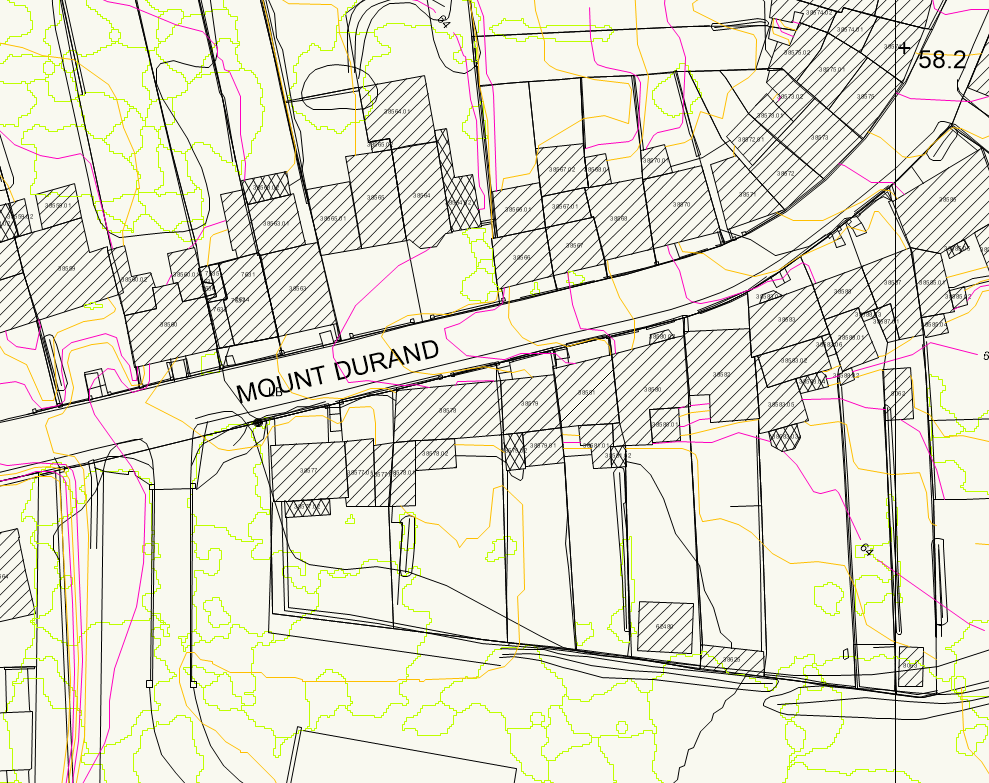
Below; 1, how it is imported. 2, how we want it to look. I have achieved this within Autocad before with a lisp file. Is this a potential option - if so any tips on how to write it?
-
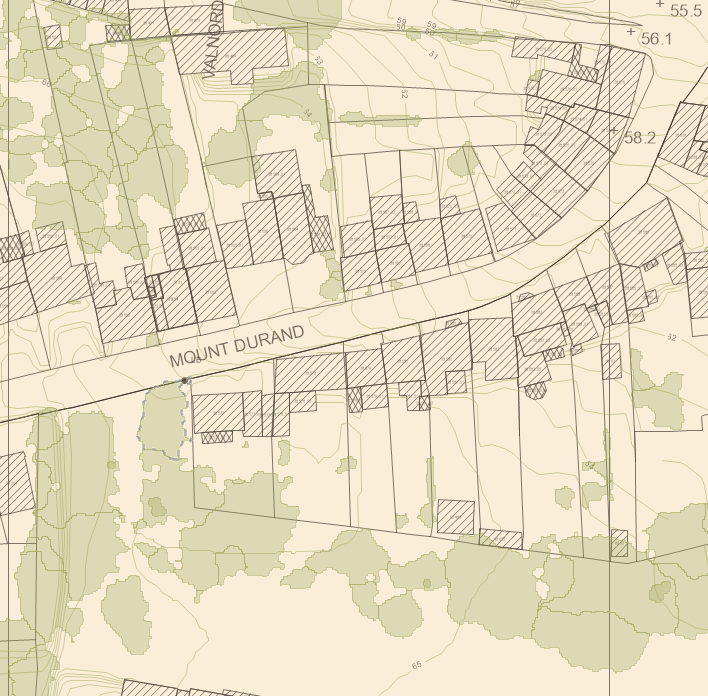
Hi all, When we start any new project we bring in the OS tile which is in dwg format. Typically, we import with a prefix then go through and turn off or delete layers we don't use, as well as change the line colours to suit our preference. I want to try and stream line this for both our OS imports but also a few other things we bring in, for example standard details etc where layer/class naming is consistent. Example 1: OS file (dwg) has a layer (dwg version of a class) called "contours" when imported this comes in with the line colour and fill as back in the class manager and magenta on the drawing as an overwritten line colour with the fill on "none". We would like this to come in on a Class called, "digi-contours" with a green line colour. Now the "digi-" can be set by setting a it as a prefix or by using a mapping set. However, if I set a template file with this class already created (with the line and fill as wanted), the import will overwrite the line and fill settings. Therefore we have to go back through and change everything again. This is time consuming and frustrating, particularly if addition OS data gets bought in later into the project. The current work around of exporting to a new file then bringing into the existing document by using the new layer > import geometry option creates Georeferencing headaches. Example 2: We are looking to use https://detail-library.co.uk/ to support our existing standard details. They have kindly shared tips for import settings, however we would like to go one step further and blend their classes(layers) with our standard layers. Again, using standard the import layer mapping, i can change the names, but the layer settings all revert when i bring it in. Can anyone help? Is this a workflow issue, or a setting issue? many thanks, Josh
-
Ah I missed the in "the resource manager" bit!
-
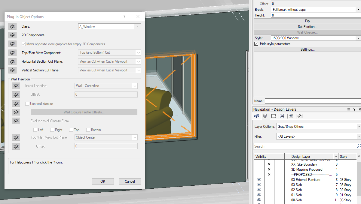
I think I am missing something... When creating a window style, is there an option to change the Class to "by instance" for the plug-in options, or alter existing window styles to be by instance, rather than by class? thanks!

-
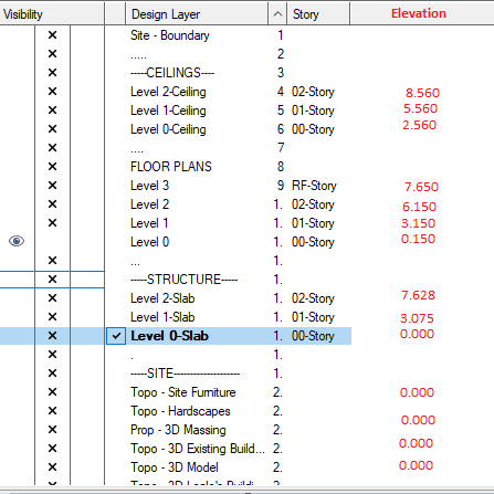
I know the ability to group layers is frequently requested, but to add to the request for updated layer organisation, can we get a column that states the elevation of each layer? As crudely shown below! Whilst usually, knowing the storey they related to suffices, sometimes it is useful on projects that for example are split level blocks of buildings to have a prompt!
-
Grouping of Layers - PLEASE
Josh S replied to bjoerka's question in Wishlist - Feature and Content Requests
It's maddening that there is no way of doing it. But to be fair even if we could add a "-" to allow a heirachy system like the classes use, it would be an improvement. Being able to link them though would be great too, although I guess that is mostly done through saved views and editing from within the viewports? This is our current work around to try and keep files organised. We would welcome any tips on improving this?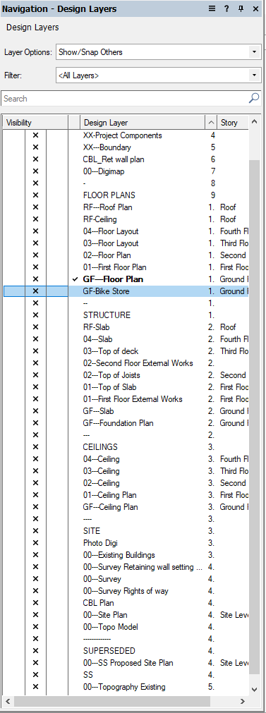
-
Stair autonumbering starting from numeral other than 1.
Josh S replied to Josh S's question in Wishlist - Feature and Content Requests
Have you a link to this wizardry? -
Unless I am mistaken there is no current way of using the autnumbering tool to make stairs start at any number other than 1. Ideally, this should be customisable so the stairs from Level 1 to Level 2 will be numbered 1-16, and then the stair from Level 2 - 3 will be numbered 17-32 and so on. Presently we have the tedious task of numbering stairs manually, which is fine until the number of treads or even the depth of tread changes and everything needs adjusting! I do appreciate stairs can just be numbered from 1 for each level, it just doesn't comply with the Directors preferences!
-
@Christiaan Bloody clip cube! cheers for this, I was just choosing which window the PC was about to go out!
-
Hi @Wes Gardner, that works well when creating the ceiling from and extrusion. I could use the cut extrusion, to create a polygon the correct size. Create a slab from that, giving me a correct slab for the ceiling. But I suppose is there any benefit at that point to using the slab for a ceiling over a simple extrusion? thanks, Josh
-
Hi, Anyone able to point me to a tutorial on creating a ceiling in an attic space? I can fudge it and get it sort of the right size but it's a b it of a faff. There must be an easier way! It's probably something simple I am over looking? The roof is made up of roof faces and the ceiling a slab. Ideally I would be able to get the slab to intersect with the soffit of the roof. TIA, Josh
-
Bi-folding sliding doors for Door Tool
Josh S replied to Christiaan's question in Wishlist - Feature and Content Requests
Thanks for the suggestion. I had a look at their products and downloaded one of their doors. They do have vectorworks formats but they aren't quite as friendly as vectorworks own doors. They are more just 3D extrudes put into a symbol. Still, better than starting from scratch! -
Bi-folding sliding doors for Door Tool
Josh S replied to Christiaan's question in Wishlist - Feature and Content Requests
I assume this hasn't been addressed in 2020 vectorworks?- 12 replies
-
- 1
-

-
- door tool
- wishes granted
- (and 1 more)
-
I quite like how the stories work. Really handy when sketching out designs and fiddling with levels. That said, they probably are less beneficial for two storey development. I'm new to vectorworks (and architecture!) this year after working as an SE Tech using AutoCAD and Revit. I swear, if you could smash Revit and Vectorworks into each other hard enough, you would have some great software!
-
Yes, likewise, I have to delete the wall peaks to reset it and get FWtO to work. I've started changing how I create my upper floor walls also. Previously, I used stories and walls would go "top of slab" to top of slab over". for this I would create a "top of slab" level on the upper most story, or a false story. Now on my upper floors I tend to set walls as from "top of slab" and the upper to wall height. Then use FWtO to get the correct elevation for the roof height. This seems to make FWtO much more consistent.
-
@Wes Gardner @David S Thank you for the comments and sorry for the slow reply. I'm struggling to upload a file to this at the moment - I have tried increasing the overhang to see if it resolves it but it still is happening. I've worked around it with negative embedment depths. I'll come back to this when I next come across it!
-
Bi-folding sliding doors for Door Tool
Josh S replied to Christiaan's question in Wishlist - Feature and Content Requests
So I'm struggling with this at present. We tend to use a lot of 3-5 leaf bifold doors around here. I have looked through a few posts and came to the conclusion Windoor is the way to go, except "WinDoor is now only available as an upgrade to existing WinDoor users residing outside Australia and New Zealand. New licenses are no longer available". Is there now a solution with 2019? Is it possible to import it as a symbol if I was to create the bifold in alternative software such as Revit, sketch-up (or even microsoft paint!)? -
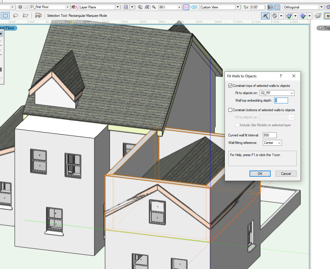
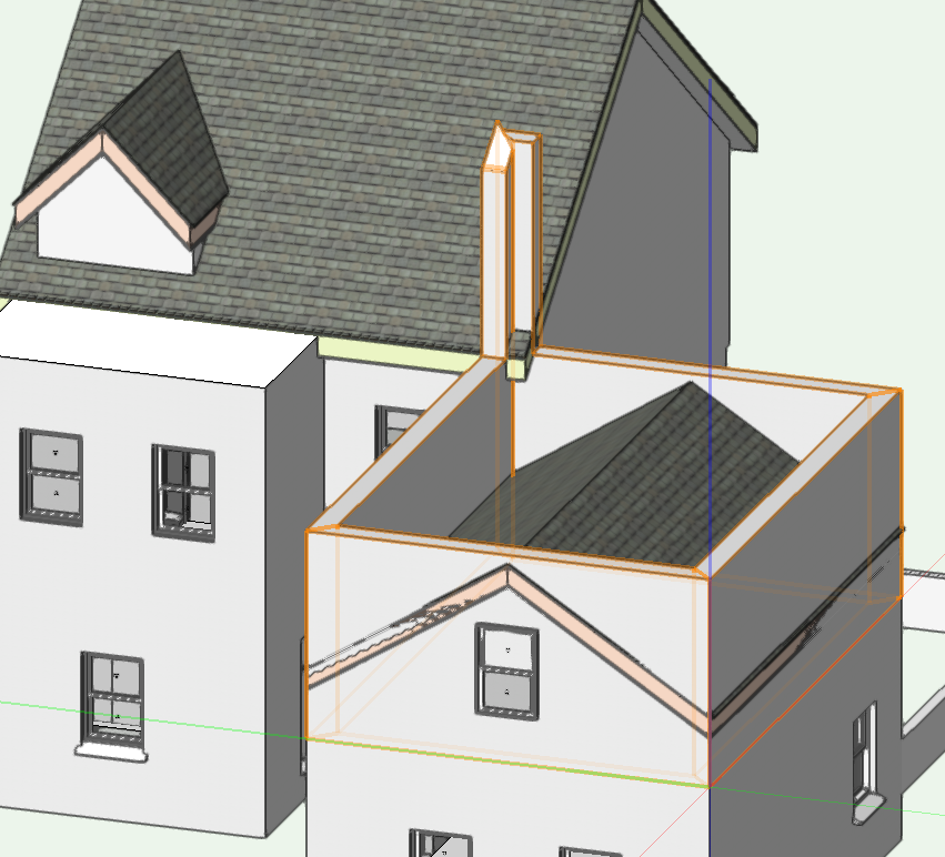
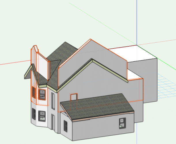
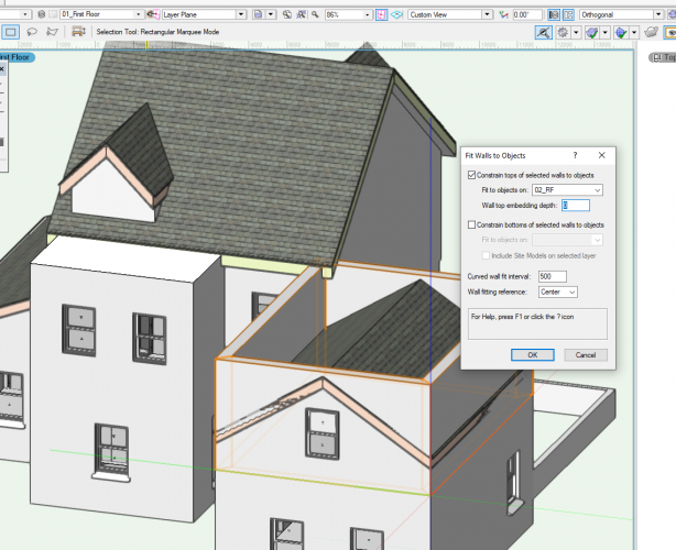
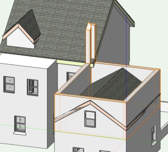
Hi! I'm having a right mare trying to get my walls to fit to my roof faces. I'm not sure if it's my workflow or a plug-in style for either the roof face or wall. Here is the settings of another example: and when I click ok: Any ideas? Cheers, Josh
-
Sorry I should have updated this. I discovered that when I purged the drawing or some other process, it deleted the bit where the layer is associated to the story. I had to go back through each later and link it back to the story. I can elaborate more tomorrow when I have vectorworks open at work if you are still stuck!
-
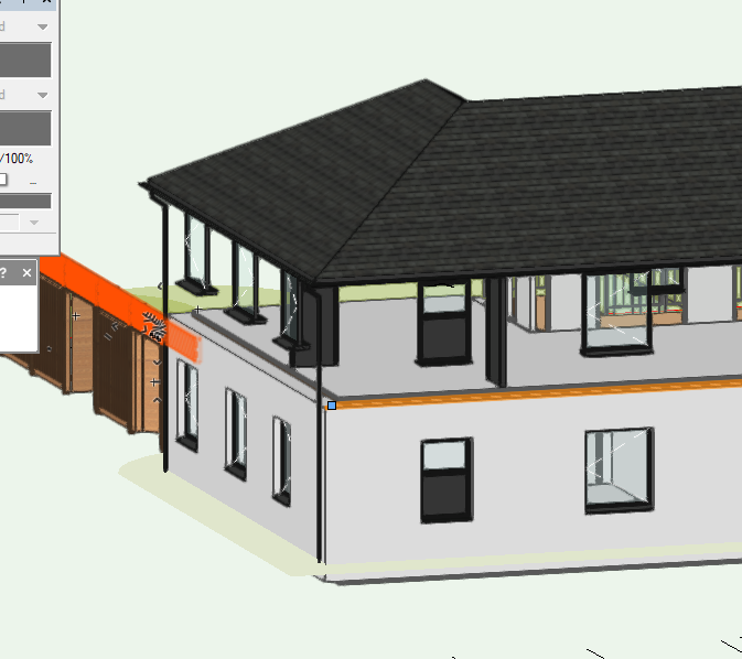
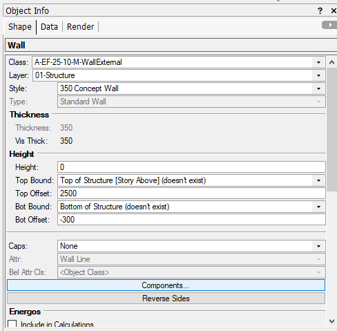
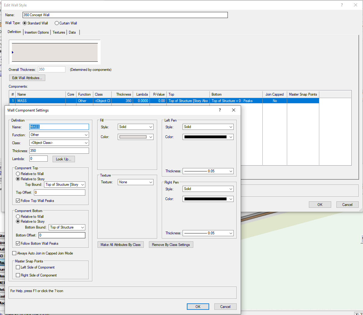
Somewhere along the line of adding the site, I lost the 1st floor walls. Then when trying to get them back I lost the ground floor too. Everything is on solid that I can see (they were a copy and paste of the ground floor and were working fine!) The walls are supposed to go from 300 below structure to the top of structure on the story above. This is the general set up I have used on the last couple of projects and seems to have worked fine. Can anyone see where I am going wrong? Hopefully, I am doing something stupid and this will be a quick fix! thanks in advance, Josh


-
That's the one! No idea when or how that got turned off! Thanks for your help. atb, Josh
-
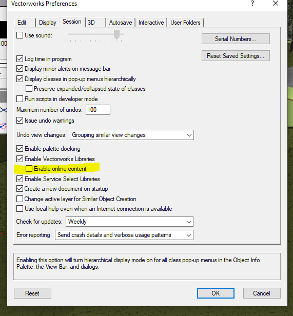
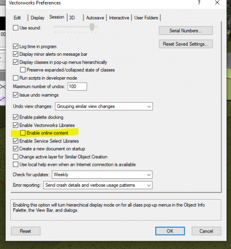
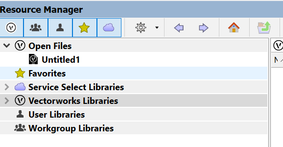
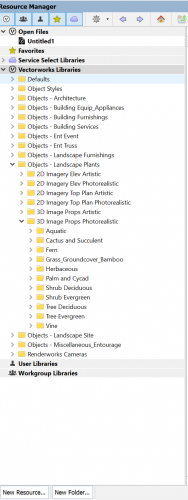
@ASagatovVW Oh that sounds promising. I'm home now so i will try this in the morning. Thank you. @zoomer This is the folder tree I have. and this is what I am hoping to find: I'll try the "Tools > Options > Vectorworks Preferences > Session Tab > Make sure "Enable Online Content" option and report back. thanks, Josh
-
Sorry, the picture is misleading and maybe my question. Their should be more folders and many more trees listed. The only tree's showing are ones I downloaded on another project. I've tried refreshing also. It's like the resource browser is not seeing the vectorworks online library? For example, if you right click the file the download option is not there.