The Hamma
-
Posts
383 -
Joined
-
Last visited
Content Type
Profiles
Forums
Events
Articles
Marionette
Store
Everything posted by The Hamma
-

Trying to move Section Viewport annoations to a new simple VP
The Hamma replied to The Hamma's topic in Vectorscript
Yep! Thanks! -
Wood Truss Tool
The Hamma replied to Sam Combs, AIA, NCARB's question in Wishlist - Feature and Content Requests
@Sam Combs, AIA, NCARB I made a tool to make a schematic truss. It’s definitely not structural by any means but it’ll make a 2D and a 3D Truss Schematic Wood Truss.vso- 1 reply
-
- 1
-

-
I have written this script and it creates a new viewport. But it stops looping after the first object. It is supposed to move all the annotation objects from the selected Section VP to the new viewport PROCEDURE ConvertSectionVP; {$debug} VAR H1,H2,H3,HVP,HVP1:HANDLE; Result:BOOLEAN; PROCEDURE CopytoNewVP(h :HANDLE); BEGIN H1:= GetVPGroup(H,2); H2:=FInGroup(H1); WHILE H2 <> NIL DO BEGIN Result:=AddVPAnnotationObject(HVP,H2); H2:=NextObj(H2); END; END; BEGIN HVP:=CreateVP(ActLayer); HVP1:= GetVPGroup(HVP,2); ForEachObject(CopytoNewVP,((((ST=SECTVIEWPORT) & (VSEL=TRUE))))); END; RUN(ConvertSectionVP); PROCEDURE ConvertSectionVP; {$debug} VAR H1,H2,H3,HVP,HVP1:HANDLE; Result:BOOLEAN; PROCEDURE CopytoNewVP(h :HANDLE); BEGIN H1:= GetVPGroup(H,2); H2:=FInGroup(H1); WHILE H2 <> NIL DO BEGIN Result:=AddVPAnnotationObject(HVP,H2); H2:=NextObj(H2); END; END; BEGIN HVP:=CreateVP(ActLayer); HVP1:= GetVPGroup(HVP,2); ForEachObject(CopytoNewVP,((((ST=SECTVIEWPORT) & (VSEL=TRUE))))); END; RUN(ConvertSectionVP); Cat Office Millwork Test.vwx
-
Ok, yes I see this one but it will only use the USER folder or the Program folder when specifiying a pathid when using this to create the full path. path := Concat(GetFolderPath(pathID), 'Walls~Slabs Styles Metric.vwx'); { pick a file within the shipped default content } I need it to look at the workgroup folder which is not always in the same place.
-
Can you direct it to a particular file in a subfolder? I assume not.
-
What is the format of "subFolderName" in buildresource list For example if the folder is Folder/Subfolder/File.txt how would I enter that. I know mac an windows have different slashes in folder paths?
-
Vectorworks 2024 drifts away overnight
The Hamma replied to VIRTUALENVIRONS's topic in General Discussion
I have had vectorworks crash when leaving it for a while unattended. But I’m on a Windows PC. -
Can't seem to find the command 'Convert to Line Light" when using DoMenubyName('Convert to Line Light',0); any ideas? or another way to convert a line to a line light using a script?
-
I figured as much, Thanks Pat and Joshua!
-
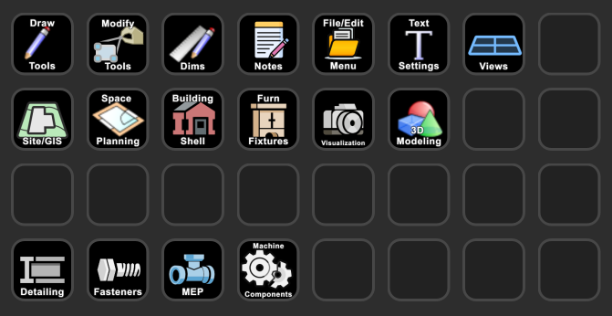
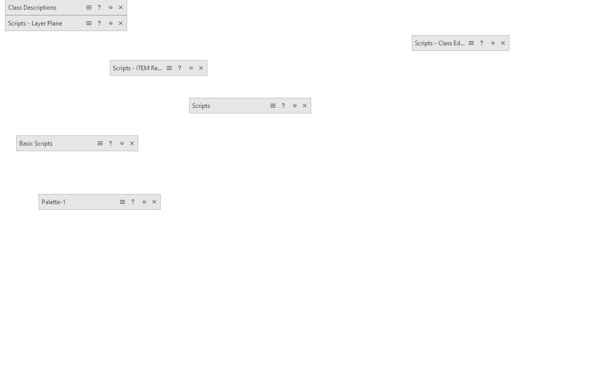
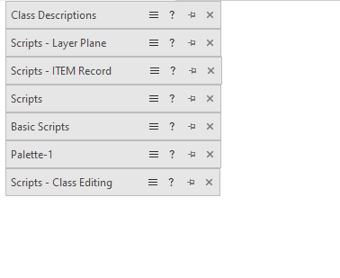
Hello All: Would anyone know if it would be possible to script a script to organize script palettes in the GUI. Manytimes they end up all over my workspace but it would be nice to have them stacked in an instant. Instead of this I would like this.

-
Better yet you could use these two plugins and give them the same shortcut in each workspace so that they switch back and forth depending on which workspace is active. Put StreamDeckWorkspaceA.vsm in the second workspace and put StreamDeckWorkspaceB.vsm into the first workspace and give them the same shortcut in each. Be sure to edit StreamDeckWorkspaceA.vsm and StreamDeckWorkspaceB.vsm to point to the corect workspace.
-
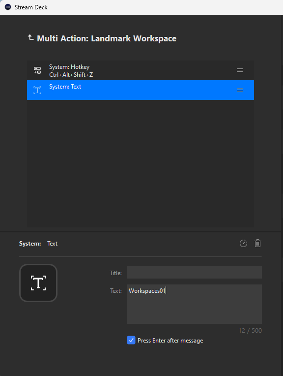
I can do this with stream deck using the attached plugin. StreamDeckCommand.vsm The Streamdeck invokes the script and types "Workspaces01" for the first listed workspace in the list. Change 01 to what ever number worksapace you are trying to switch to. The StreamDeckCommand.vsmmust be added to your workspaces and given a shorcut. In my case the shortcut I added to the command is Ctrl+Alt+Shift+Z
-
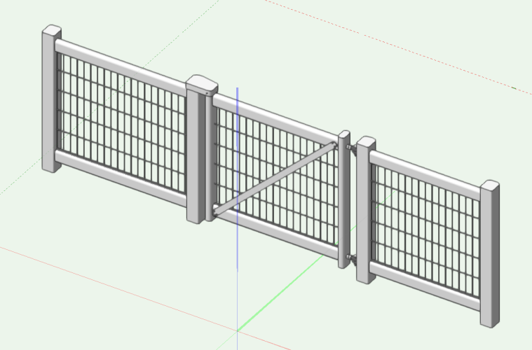
I made a new fence style to match the Equinox Racing Tecrail Crowd Barrier for a local fairgrounds. I thought I would share. See attached VWX file. Equinox Racing Tecrail Crowd Barrier.vwx
- 1 reply
-
- 7
-
-
I have created a point object ot create Pre-Engineered Metal Builidng trim for Doors and windows. I would like to have it also create a 3D hole object. Does anyone know how to do this? PROCEDURE PEMBOpeningTrimPointObject; CONST SourceSub = ''; {Sub path} ResType = 94; {Class Def} folderIndex = -8; {Standards} VAR unitmultiplier,JambComp:REAL; H2,H3,H4: Handle; Result:BOOLEAN; ResourceName:STRING; currentunits,ListId,NumItems:LONGINT; CNo:INTEGER; PROCEDURE ImportClass; BEGIN ListId:= BuildResourceList(ResType,folderIndex,SourceSub,NumItems); WHILE NumItems <> 0 DO BEGIN ResourceName:=GetNameFromResourceList(ListId,NumItems); IF (ResourceName = PClass1) THEN BEGIN H4 := GetResourceFromList(listID, NumItems); if (H4 = NIL) then H4 := ImportResourceToCurrentFile(listID, NumItems); END; NumItems := NumItems-1; END; END; BEGIN unitmultiplier := 1 ; currentunits := GetPrefInt(170); {assign the current document units interger to currentunits varaiable} if currentunits = 1 THEN unitmultiplier := 25.4; if currentunits = 2 THEN unitmultiplier := 25.4; if currentunits = 3 THEN unitmultiplier := 304.8; if currentunits = 4 THEN unitmultiplier := 914.4; if currentunits = 5 THEN unitmultiplier := 1609000; if currentunits = 7 THEN unitmultiplier := 1; if currentunits = 8 THEN unitmultiplier := 10; if currentunits = 9 THEN unitmultiplier := 1000; if currentunits = 10 THEN unitmultiplier := 1000000; BeginGroupN(H2); {Import Classes if they don't exist} CNo:=ClassNum; NameClass(PClass1); IF CNo < ClassNum THEN BEGIN DelClass(PClass1); ImportClass; END; if PCreateSill = TRUE THEN JambComp := 0 ELSE JambComp := PDoorJambThickness; {Compensate for door jamb thickness} {Create the Trim} BeginXtrd(0,PTrimDepth); RectangleN(POpeningWidth/2+PTrimWidth+JambComp,PHeadHeight-.01+JambComp,0,90,PTrimWidth+.01,POpeningWidth+PTrimWidth*2+JambComp*2); RectangleN(POpeningWidth/2+PTrimWidth-.01+JambComp,PHeadHeight-POpeningHeight,0,90,POpeningHeight+JambComp,PTrimWidth+.01); RectangleN(-POpeningWidth/2-PTrimWidth+.01-JambComp,PHeadHeight-POpeningHeight,0,90,POpeningHeight+JambComp,-PTrimWidth-.01); if PCreateSill = TRUE THEN RectangleN(POpeningWidth/2+PTrimWidth,PHeadHeight-POpeningHeight-PTrimWidth+.01,0,90,PTrimWidth+.01,POpeningWidth+PTrimWidth*2); SetClass(LNewObj,PClass1); SetFPatByClass(LNewObj); SetLWByClass(LNewObj); SetTextStyleByClass(LNewObj); EndXtrd; SetClass(LNewObj,PClass1); SetFPatByClass(LNewObj); SetLWByClass(LNewObj); SetTextStyleByClass(LNewObj); EndGroup; Rotate3D(90,0,0); {Move object so it insets into wall} Move3DObj(H2,0,.01,0); Locus(0,0); END; RUN(PEMBOpeningTrimPointObject);
-
Get handle of object that data tag is associated with
The Hamma replied to The Hamma's topic in Vectorscript
Script to center selected space tags on associatied spaces. PROCEDURE MoveSDTScript; {script to center selected space tags on associatied spaces. note if the handle for the space is outside the boundry of the space the tag will be centered on the space and the bounding point} VAR h,h2 :HANDLE; index,associationkind,value:INTEGER; phx,phy,ph2x,ph2y:real; FUNCTION MoveDT(h :HANDLE) :BOOLEAN; BEGIN h2:=GetAssociation(h,index,associationkind,value); Hcenter(h,phx,phy); Hcenter(h2,ph2x,ph2y); HMove(h,ph2x-phx,ph2y-phy); END; BEGIN ForEachObjectInLayer(MoveDT,2,0,2); END; RUN(MoveSDTScript); -
Get handle of object that data tag is associated with
The Hamma replied to The Hamma's topic in Vectorscript
That is it, thanks. -
In a vectorscript, does anyone know how to get the handle of an object that a data tag is associated with. Specifically I am trying to get the handle to a space from selecting the data tag for that space.
-
Streamdeck integration.
The Hamma replied to Matster's question in Wishlist - Feature and Content Requests
The one "above at this link" is the latest one that has not been custimized to my personal workspace. Any reason why you want me to repost it? -
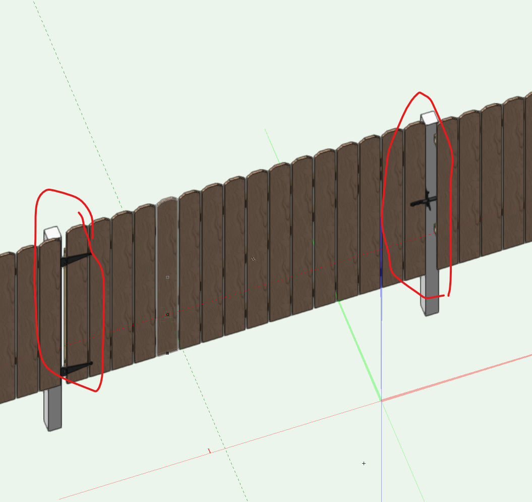
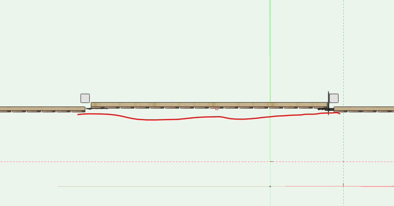
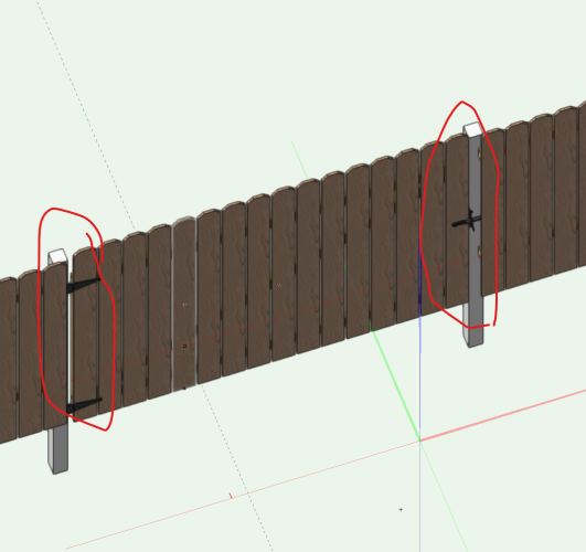
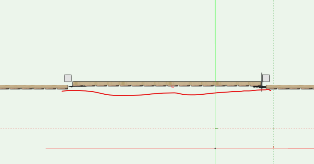
I may have missed this but I have modified a wood gate to be on the correct side of the fence but I can not make it flush out with the face of the gate or elimate the gap between the center of the post and the gate. Anyone have a way to do this? Fence Gate.vwx
-
@Jesse Cogswell, I just found this script and it is awesome. Just wanted to make everyone aware that besides the issues as noted by @MarcelP102 above the script also does not work well when the user origin is not the internal origin. The symbol will displace and the symbol's internal origin will also be offset. Jesse if you figure out how to fix the origin issue please let me know as I have a drawing label aigning script that also has the same issue.
-
Import spreadsheet data into vectorworks and assign to record format.
The Hamma replied to The Hamma's topic in Vectorscript
Sorry I gave up on this. -
Streamdeck integration.
The Hamma replied to Matster's question in Wishlist - Feature and Content Requests
I installed this profile on my Window machine and none of the commands work but all of the instructions are correct. It appears the hotkey functions are not interchangable between Windows and Mac. If I replace the "F" hot key with a "F" it processes half of the command. I have to replace the "Return" hot key with a "Return" and it processes the entire command. Not sure why they are different. -
Streamdeck integration.
The Hamma replied to Matster's question in Wishlist - Feature and Content Requests
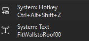
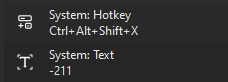
Yes I think this should be Platform- agnostic but it is slower than the method that I just posted that uses the two plugin scripts which should also be Platform-Agnostic but I have not tested it on a Mac. This version uses the names of the Commands, Tools or tool indexes rather than shortcuts except for the shortcuts for: Which it uses to call the plugins and awaits the name of the tool which is sent from Stream Deck Menu command call (note if there is not a chunk number you must add 00 to the end of every command, if there is a chunk number enter 01 for 1 and 10 for 10) Tool Name Call Tool Index call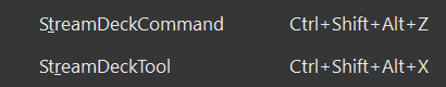
-
Link to the my stream deck profile that I posted.
-
Streamdeck integration.
The Hamma replied to Matster's question in Wishlist - Feature and Content Requests
Here is my Stream Deck Profile for the Standard Architect Workspace. I requires that you add the two attached plugins to your workspace and set their shortcuts as shown. Feel free to re-arrange as you see fit. v Vectorworks 2024 Stream Deck.zip