


Anna Guzman
-
Posts
38 -
Joined
-
Last visited
Content Type
Profiles
Forums
Events
Articles
Marionette
Store
Posts posted by Anna Guzman
-
-
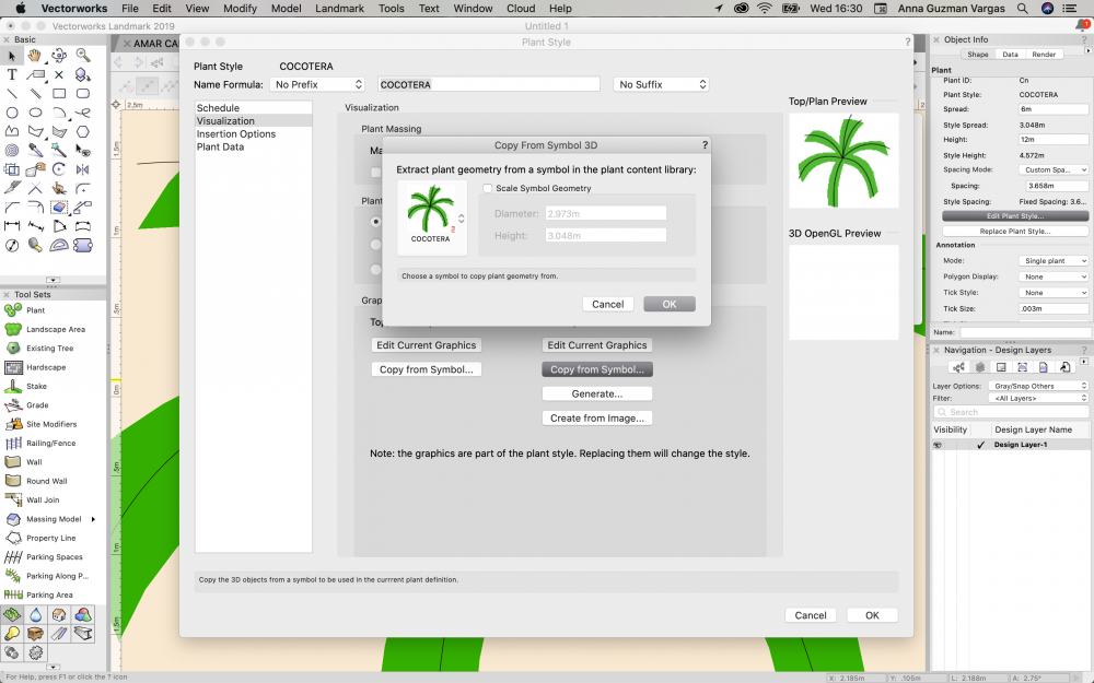
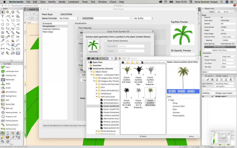
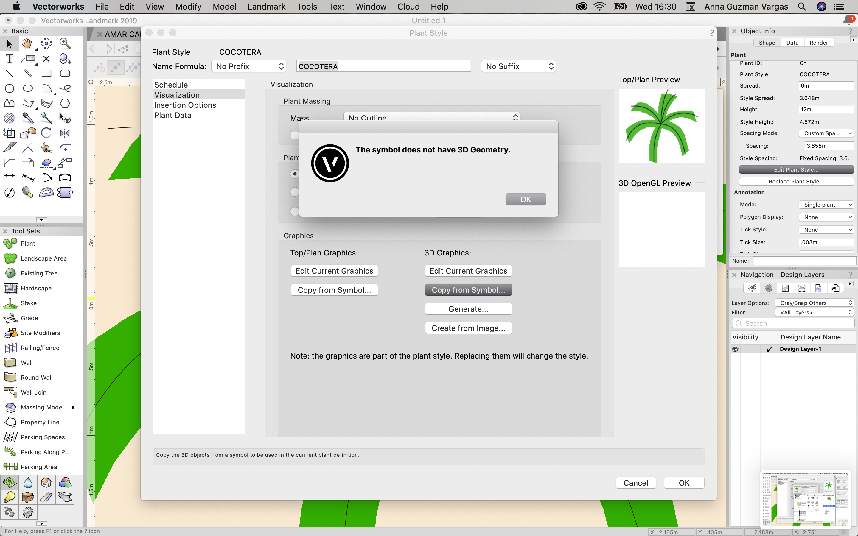
Hello! I am having trouble loading a 3d symbol for a palm tree I have on my model. I chose an entourage plant symbol in 2d, got plant data for my schedule from the plant catalogo "cocos nucifera", and the data downloaded correctly. But when trying to copy symbol, an error message pops up saying "the symbol does not have 3d geometry". Can anyone help and point out what I'm missing or what I'm not doing correctly? I'm attaching screenshots of the steps I'm doing. Thanks!!!

-
@Boh THANK YOU! this sounds very helpful as well! I´ll work with both and see which one better works for us! thanks!
-
 1
1
-
-
@Tamsin Slatter THANK YOU! Good thing I asked before setting all of my dimensions!
-
 1
1
-
-
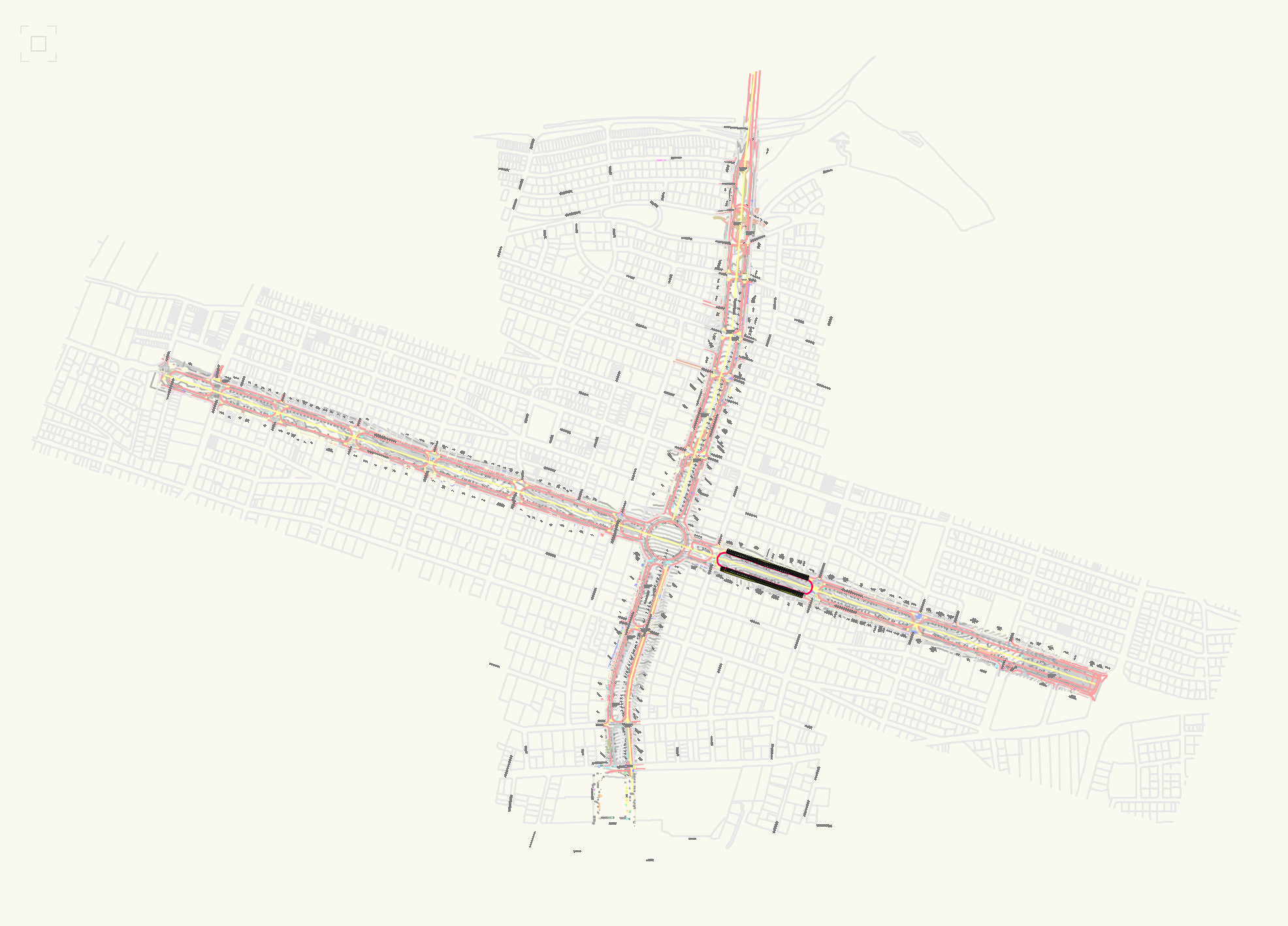
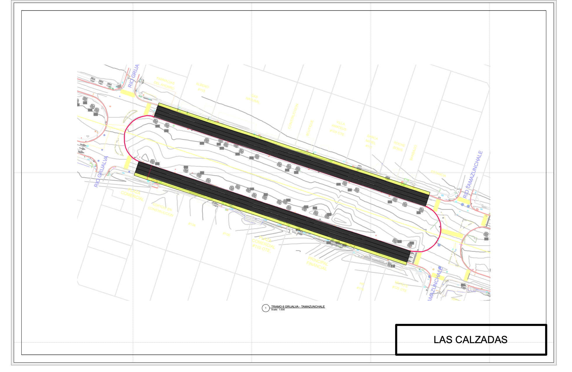
Hello, newbie at Vectorworks and still transitioning from Autocad. I have a street plan drawn on my design layers, and I just created a new sheet layer to print my drawings.
This is my plan on design layer:

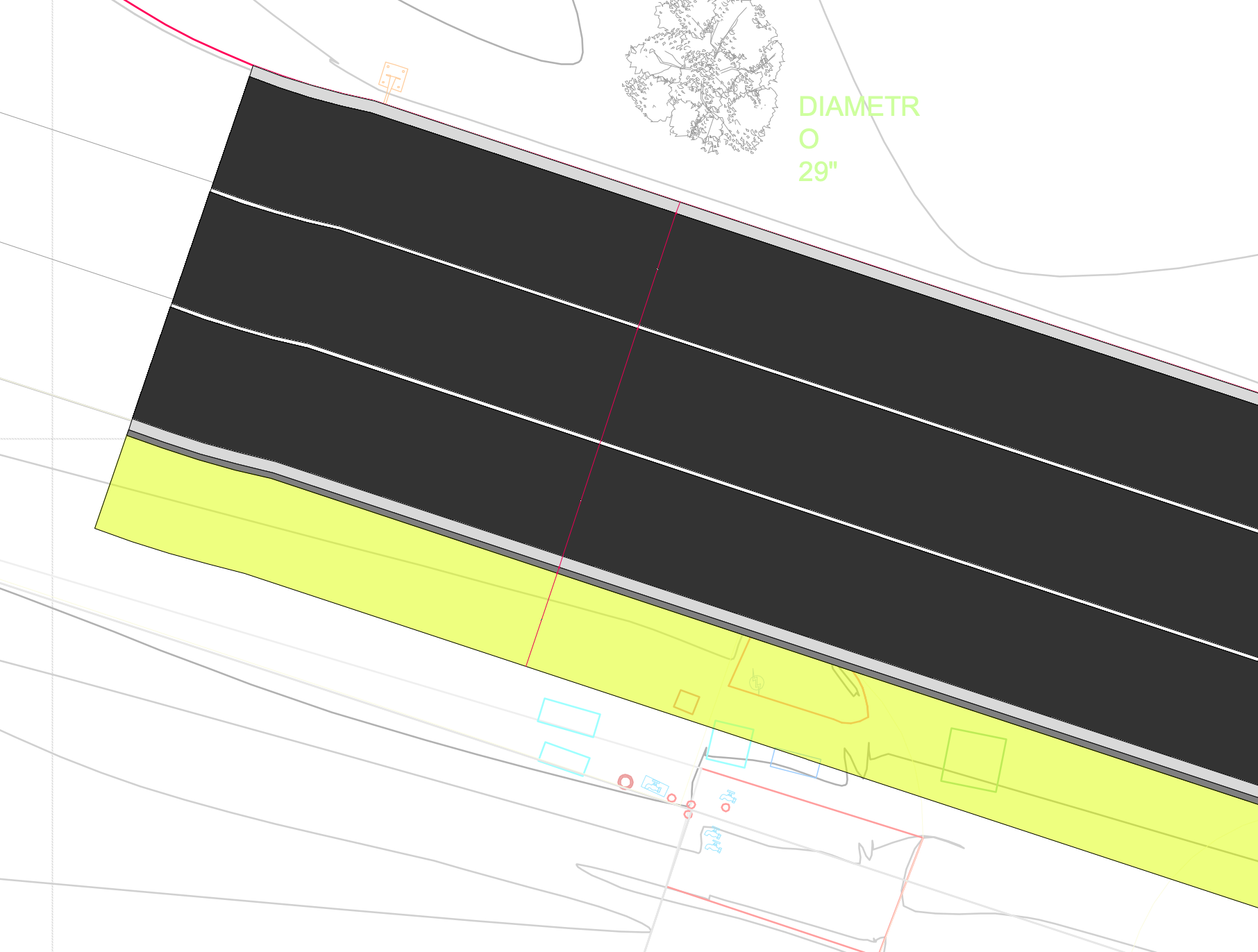
But I have issues with text sizes and dimension sizes. On my design layer I work on a 1:1 scale, so I have to set my text size to almost 2,000 points in order to see them. Is there a way to change this and make it more efficient? Also on my sheet I set my drawing at 1:500 for it to fit on the page, and I can't see my texts or dimensions.
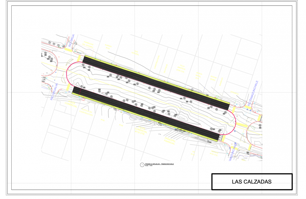
Is there something I need to set somewhere to be able to see dimensions? That red line that crosses my street section are the dimensions but I can't see anything.
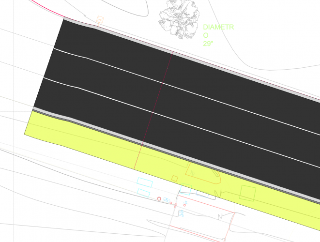
Thank you.
-
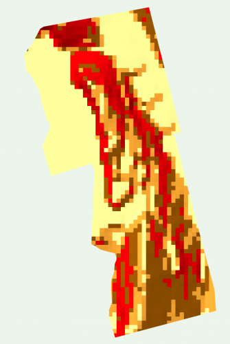
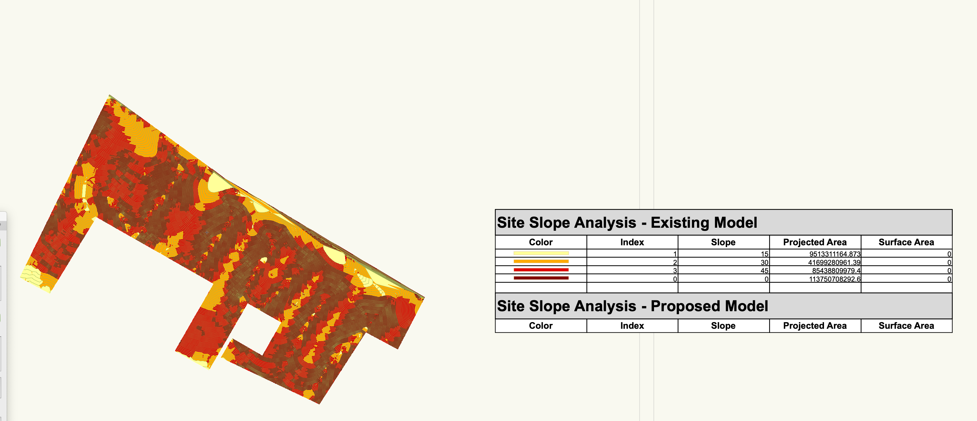
Hello, still new to Vectorworks, and trying to create a SITE MODEL SLOPE ANALYSIS REPORT from the 3d grid colored slopes. I can't seem to get the area for each slope range. I managed to create on from the 2d colored slopes but I think its not grid based, and I get weird areas. How can I get a report like this one, but based on the 3d grid colored slopes? Or what is it that this preformatted report is counting in the "projected area" and why am I getting such big amounts of square meters?

This is the site I want a report on. I have the colored slope grid, but how can I add the area depending on the color?
-
@Andy Broomell thanks! It does remove that white halo that trees usually have!
-
1
-
-
Ok, so I made the image prop in another file and it worked, then I copied it to my model file, with no problems. I guess my model file must have some sort of bug or something. Thanks anyways!
-
1
-
-
@Jim Wilson yes, they also show up when rendered, I was able to do one or two tree image props, but suddenly the frame started showing up
-
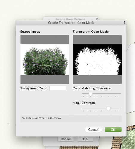
Hello, can anyone help me out, when trying to create an image prop, these gray lines like frames keep showing up, I have photoshopped the image and has no background and is saved as png. When trying to mask the image an choosing the transparent color, it shows up with that gray frame, anyone had this problem before???
-
Thank you, I will give that a try, I'm having a little trouble understanding how to use the site modifiers but I´ll try that. Thank you!
-
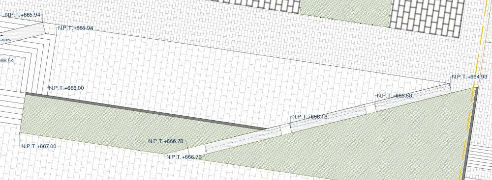
Hello, I have a hardscape area with different "stakes" or spot elevations on each vertex. How do I model this? First time Vectorworks user.
-
Hello! When combining slabs, does the slab drainage system auto-update or is it not possible to combine slabs with drainage systems?
-
1
-


3D PLANT PROBLEM
in Troubleshooting
Posted
Thanks Tamsin, but is there a way to use the 2D elevation images as image props, and create a symbol from that image prop to use as a 3D symbol? That's what I'm trying to do, I also tried to choose a 3d symbol directly for the plant but the ""the symbol does not have 3d geometry" message keeps popping up.