


Daniel Dickman
-
Posts
101 -
Joined
-
Last visited
Content Type
Profiles
Forums
Events
Articles
Marionette
Store
Posts posted by Daniel Dickman
-
-
On 4/12/2018 at 2:50 PM, Jakepforbes said:
Kevin,
That seemed to work for me. Maybe you can also tell me if there is a way to make it break up horizontally kind of like the picture you sent. Basically Im trying to fit this across the bottom of my page so after about 7 sheets I would like it to make a new column for sheets 8-16 and then go into another column and so on so all this can fit into the orientation I have set up. Is this possible or do I need to change the look of my whole cover page?
@Jakepforbes Did you ever find a solution for this? I have a similar need to break up a report due to height restrictions.
Also to the rest of the community, when creating a report to use as table of contents, how can I go about filtering out specific sheets? I have various sheets that are just for sketch purposes and I don't want them included in my TOC. I have "print" and "non-print" filters created to help me when navigating my sheet layers... Can I leverage those filters when creating a report?
Edit: Found some solutions to filtering out specific sheets from these lists.
-
Hey friends,
I've finally gotten around to really digging into ConnectCAD and I created a dummy showfile mirrored after some of the facilities we work on at our office. Attached are the PDF sheets and the VW file.
This has been a good exercise to get used to the ConnectCAD workflow, but I did come out of it with some questions. They are all written in the VW file but I'll post them here as well to see if I can get any clarification from the community.
- Room Tool - Is there any way to use the room tool on the schematic design layer. When I was drawing my schematic views, I was already drawing rectangles to define location/rack. When I finally got to a point where I was ready to drop gear into racks, it seemed like double work to draw all of the rooms again on the rack elevation design layer. I would be awesome to define all of these location in the schematic view. Then use the update elevation function when i'm ready to define where gear lives in each rack.
- Cable Type Tags - Is there a way to move multiple cable type tags at once? After using the reroute tool, I would find myself having to reorganize all the cable tags one by one to make them line up again.
- Data Patch Panels - Using the Data Term Panel Tool, how can I define the connector on the front AND back of the panel. Our RJ45 patch panels typically are punchdown on the backside and would like to call that out.
- Connector Panel - Similar question as above. How do I define the connector on the front AND back. Some of our DMX venue outputs are terminal strip inside the Jbox. Some RJ45s are punchdowns in the JBOX.
- Symbols - I've seen a lot of suggestions in this forum about saving connectCAD devices as symbols for re-use later. I was doing this but then once I started connecting devices, I would realize that a socket would have its signal set incorrectly. I attempted editing the symbol in the resource manger to set the missing socket signal, but the exiting instances of that symbol would did not update. Is there a way to update existing instances of a symbol so I don't have to edit each one individually?
- Patch Panels - Turn off Rack name - My rack names are typically something like NWK-001 or LTG-001, these tend to be too long and over lap with the connector type in the schematic drawing. Is there a way to turn off the location name besides deleting from the symbol?
- 2D Rack Elevations - Is there a way to draw a 2D front view and 2D rear view of a rack? It seems that all front and rear mounted devices appear in the 2D rack elevation and its hard to tell what is a rear mounted device.
Okay I think that is probably enough questions for now. Loving ConnectCAD so far, just trying to wrap my head around the best workflow for my team's purposes.
-
On 1/31/2020 at 7:13 AM, jcogdell said:
The files are located in the Vectoworks application folder,
Vectorworks 2020 > Plug-Ins > connectCAD-Data
@JCodgell When modifying the signal types and connector types, I'm not able to see my new additions in a drop down until I restart Vectorworks. Is there function in ConnectCAD to refresh these lists without having to restart VW?
-
@Nikolay Zhelyazkov That did the tirck. I set the VJX_label and TP_label symbols to reference the color set by the class.
What is the purpose for the symbol drop down in the OIP for these devices? VJX_label and TP_Label aren't listed as options in that symbol drop down of the OIP. It is set to dev_label_center by default when you create these devices.
-
@Nikolay Zhelyazkov Please take a look at the attached file.
ConnectCad Text Color Class Testing.vwx ConnectCad Text Color Class Testing.pdf
-
@Nikolay Zhelyazkov Just getting back around to this.. Refreshing the device's symbol via the OIP does force the device to apply the color via the class, but it changes the text size of the device. This poses a problem specifically for how jackfield objects appear.
-
If i'm understanding correctly, you are looking for your label legends to display in the schematic views but not in the plan view of your plot? You can already turn off individual elements of your label legend via classes. If you are using viewports on your sheet layers, you should be able to selectively turn on/off the label legends as needed. Create a viewport of the schematic view and make sure the "Lighting-Label-xxx" classes are turned on. Create another viewport of your plan view and turn off the "Lighting-Label-xxx" classes.
-
 2
2
-
-
There is lots of info in this thread. The main thing I've learned is that schematic view will not work if you have converted your ladder/pipe to a hang position. It needs to be a standard rigging object, do not convert to a hang position.
-
2
-
-
@rseybert Sorry for the confusion, my post was in regards to the 2D schematic used to create signal riser diagrams within ConnectCAD not the schematic views in Spotlight. (But I do feel the pain with that tool, and have been active in that thread) I think it might benefit Vectorworks to find some better naming conventions to differentiate between these two tools. Maybe "hybrid elevations" would make more sense for the spotlight schematic tool.
@Conrad P Yes, having spotlight and ConnectCAD talk to each other would be awesome. In regards to pre-made ConnectCAD symbols/devices, do you see a time where prebuilt devices will move out of the device builder tool and into the spotlight/service select symbol libraries?
-
Having the same issue here. I thought I messed something up in my file today. Glad to hear it's a known issue and a fix is in the works.
-
I there any way to link data between 2D schematic objects and spotlight lighting instruments? It would be interesting to have the ability to import a lighting symbol from the vectorworks library that includes 2D geometry, 3D geometry AND a 2D schematic representation with all physical connections. I would love to find a workflow that links a lighting symbol in my plot to the 2D schematic instance. This way, when I update a channel number/DMX address/position on a light plot, that information would automatically update in the 2D schematic instance of that fixture.
Does that make any sense? Does anyone have a similar workflow already?
-
On 1/7/2020 at 12:05 PM, collinadams94 said:
Is anyone having issues with the connect tool reversing the connector type and cable number on one side of the connection? One side has cable number on top of line and the connector type on the bottom, the other side is reversed (please reference screenshot).
I have had this issue as well. It seems that you have to make all the connection in the exact same direction. If you start making connections going from the left device to the right, they will all match. But if you later add another connection going from the right device to the left device, the labels on that line will be flipped.
-
@TomWhiteLight Thanks for your detailed response. We ran into another interesting issue today. When using schematic views with rigging objects (not converted to light positions) and you give position information to the lighting fixtures... the 2D schematic representations of the light fixtures all disappear. If you remove the position name from the fixtures, they reappear on the schematic view. Thoughts?
-
1
-
-
I'm trying to change the color of all magenta text. I've changed the color of all classes with a magenta pen color but my Conn Panel Outputs and Data Terms are still labeled in magenta color. I've attempted to edit the sys symbols to see if I can change the text color there but no luck? Does anyone know how I can change the color of these labels?
-
Our office just upgraded to 2020 and we are having some similar confusion regarding the intended behavior of the schematic view tools. It seems that creating schematic views from a ladder (not a hang position) and a ladder (converted to a hang position) has different results in the schematic view. For our purposes, the schematic view created by a ladder that is not a hang position results in what we expected to see (a front view with 2D lighting symbols and label legends). When you create a schematic view of ladder that has been converted to a hang position, the front view schematic shows front view 3D lighting symbols. Sure this is useful for showing how the fixtures are physically hung, but we also want the ability to show the 2D symbols and label legends for fixture info.
Attached is my test file.
-
I don't think that is it... the color fields are all empty.
-
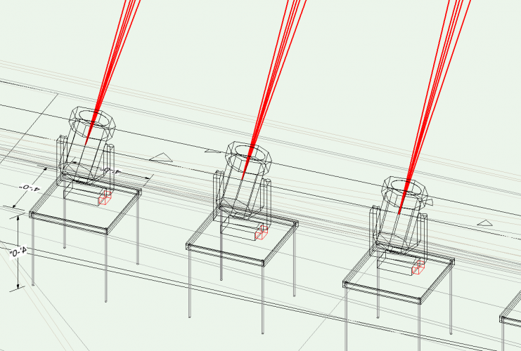
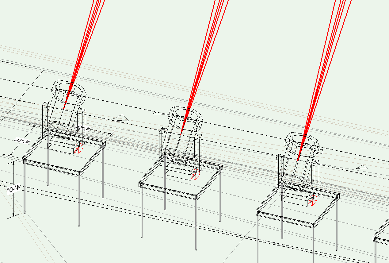
So I'm not quite sure what I did, but when I have "draw beam" turned on for my lighting fixtures, all of the beams drawn are red. How do I get the beams back to the default black?
I've checked my beam class as well as the attributes pallet for the the fixtures. Everything seems to be set to black.
Any ideas?
-
In the press release regarding this acquisition, it mentions that ConnectCAD will be "offered as an add-on module for Vectorworks Spotlight or Designer." Does this mean it will be an additional cost? Or will this be included in the price of a Spotlight/Designer licence?
-
On 2/15/2019 at 9:09 AM, Matt Panzer said:
Actually, there's a preformatted report called Drawing List that does this for you. Use the Create Report command, set the Type to "Preformatted" and select "Drawing List".
I this pre-formatted report available to Spotlight users? I don't see it in the list.
-
Hello everyone,
For a while now, I have been struggling to find an efficient workflow for drawing non-horizontal lighting positions in Vectorworks. The challenge I'm having is finding the best way to only have 1 instance of each fixture in both 2D and 3D views. For my purposes, accurate 3D positioning of the whole rig is incredibly important as my end goal is to export the plot into GrandMA2 for programming. 2D views are equally important for clean plots, hang tapes, etc.
I have been playing with the Vectorworks visualization tool called "Create Plot and Model View." [app-help.vectorworks.net] I'm sure a lot of you are familiar with it and have seen a lot of posts here regarding it. This tool lets you draw your non-horizontal positions in 2D/Plan View and then create a design layer viewport that shows a 3D model of the position that you can then rotate and position in space accurately. At first, this functionality seems great because I can use the 2D views for label legends, plots and hang tapes. At the same time I can have a true to life 3D model for photometrics, renderings and I had hoped for accurate MA2 export.
Where I'm struggling with this tool is that the 3D model view is just a 3D viewport referenced from the fixtures/positions drawn in 2D/Plan view. If you attempt to run the MA2 export plugin, all of the the non-horizontal positional will use the fixture positioning from the 2D/Plan View where the fixtures were created/defined. (On the ground, horizontally)
For shows that have these non-horizontal positions, the only way I have found to accurately get these positions to export correctly into MA3D is to draw them entirely in 3D. This ends up being very cumbersome when you want to create plots and hang tapes.
Is there any way to pull the position information from the 3D viewport of the lighting fixtures created with "create plot and model view?" -
So I've used the Create Plot and Model Views to create a couple vertical lighting ladders. But I'm a bit confused in regards to where vectorworks thinks the actual vertical fixtures are in real life.
My goal is to eventually use the GrandMA2 exporter plugin to get my 3D fixture locations in to my showfile. Since the Create Plot and Model View tools is just creating a viewport, when I export to MA2, won't the position information for my ladder fixtures be coming from the definition layer and thus be incorrect?
Am I missing something?
-
Same issue here. I have a class with the same name as the viewport I am attempting to create and it is telling me " the viewport name is already being used by another object." Seems odd that a class and viewport couldn't share the same name as they are two entirely different things.
-
Thank you!!! That did the trick!
-
Greetings,
I'm using focus points and the draw beam features in spotlight and am currently working on getting all of my viewports plated into sheet layers for publishing.
I'm running into a bit of a snag where I have some viewports where I would like to see the lighting beams and others where I would like them to be off. How can i achieve this since this is a feature of the lighting fixture itself and not a class?
Any advice would be greatly appreciated!

Data visualisation in schematic views
in Entertainment
Posted
Speaking of data visualizations, is there an easy way to create a key for data visualization. For example I have a visualization where each universe of DMX is shown as a different color and would like a key to show what color represents what universe.