Ben Beaumont
-
Posts
105 -
Joined
-
Last visited
2 Followers

-
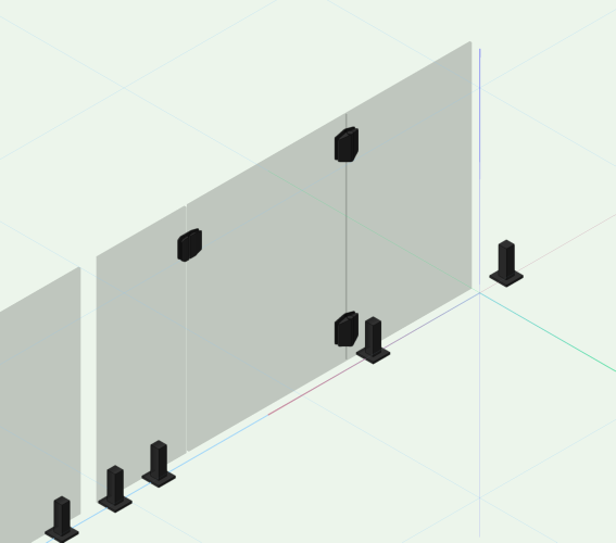
Thank you @Peter Neufeld.. It took some tweaking, but I got it working (mostly) by considering neighbouring spigots as a single post. We just end up with an orphaned spigot at the end of a run, that's all. But that's easily fixed by ungrouping and deleting. The handgate works nicely - with the safety latches and self closing hinges included. @brody98 you'll find the Swimming Pool (glass) Fence Style options in the tool selector under ANZ Swimming Pool AS1926.1 ...
-

Apply Fill Across Plant Group has bug
Ben Beaumont replied to John Moe's question in Troubleshooting
@John MoeThere is an issue with some of the (strappy leaf/ succulent type) 2d plant graphics not displaying correctly as a group when 'Apply fill across plant group' is checked. It is fixed for 2024. You can fix it yourself by rebuilding and/or inserting the filled polyline/polygon that appears at the back of the stack on Class 'Plants-Component-Color Fill'. That's the object that is unified to create the silhouette graphic. Tip: To quickly create the silhouette poly, use the polygon in 'outer boundary mode' and mouse around the folliage graphic. [CD-3937] -
@Benson ShawI'll need to come back to you on how the Property Line behaves. If one draws a Property Line at the meridian of a CRS (so it's true and square) and change the longitude of the Internal Origin, we might expect the Property to become distorted on transformation - but it doesn't behave that way. The insertion of the object is shifted, but the regular shape and rotation is preserved. The Property Line tool may not be Geo aware - it may not show convergence. It's a question for the engineers. The Rotate Plan feature is a bit like picking up your monitor and turning it like a steering wheel so you don't need to crank your head. It's of transient help only. I think a better way to 'hard wire' your project to a "project north" would be to use the key-in Angle to True North and/or the Geolocate compass tool (yes, your option B). That way you could 'set and forget' the dominant geometry of your project to the regular internal Vectorworks cartesian grid AND preserve the geolocation.
-
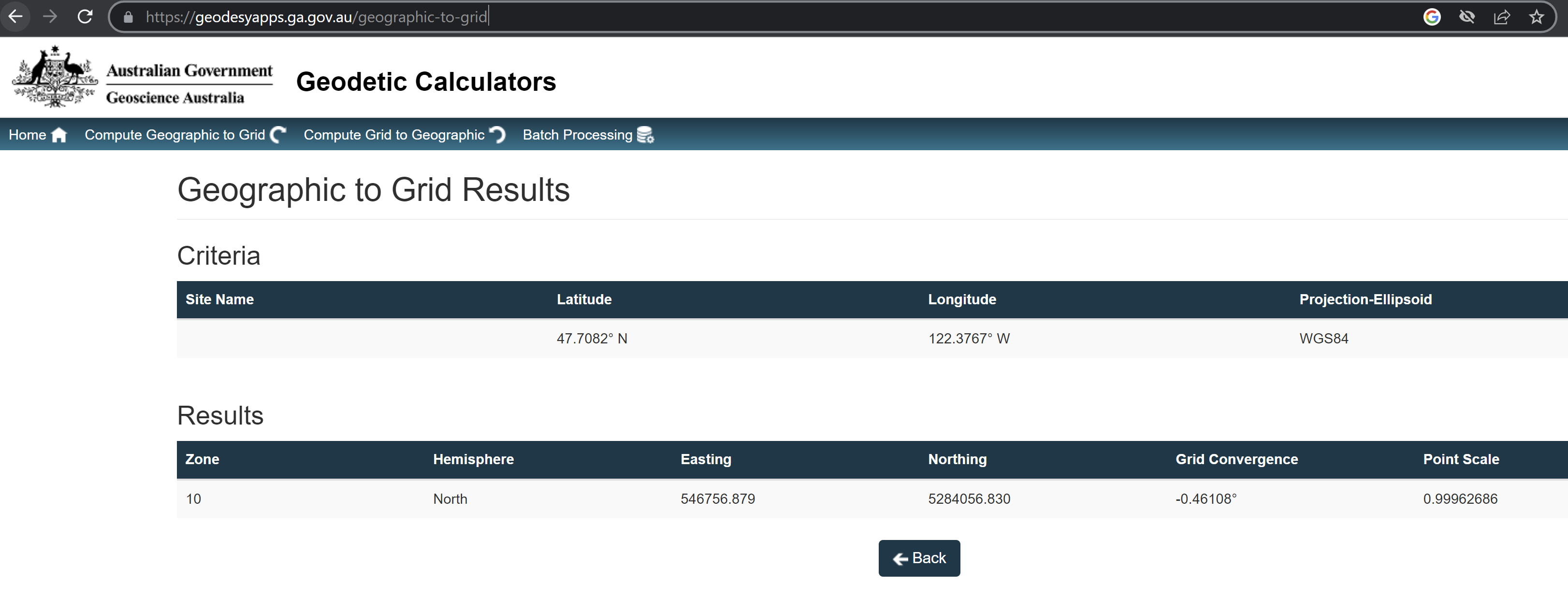
@Benson ShawI think you're asking about grid convergence. In the State of Victoria in Australia, the meridian of the CRS is line of longitude 147deg East. This has a grid convergence of zero. In Metro Melbourne, at long 145 E, the grid convergence is -1.226deg. [I established that from an online geodetic calculator.] That means the True North point is slightly anticlockwise (East) from Grid North directly up the screen. So yes, technically, we could take that into consideration when displaying a North point on our drawings. As you've pointed out, the CRS is a projection of the earth at a given point and will inevitably be a distortion of the true geometry at a granular scale. The values are generally small enough to ignore. However I believe - if you're working in a CRS - Vectorworks already knows the grid convergence value at the location you've nominated. In other words, Vectorworks knows (quietly in the background) where True North is at that point. So a value you may place in that field will be in relation to True North. That would be useful if you wanted to rotate your plan to establish a convenient 'project north' - ie; pivot the World underneath your project a convenient amount to make your building square with the internal cartesian grid of Vectorworks. Your project can still be geolocated... but conveniently displayed orthogonally to your computer screen. For your Lat/Long above I get a grid convergence of -0.46 using the Geoscience Australia calculator. But you'll need to do your own due dilligence on that. I'm not a GIS professional - I'm self-taught (teaching) in GIS... so hopefully I'm on the money with my explanation here.

-
@c.markusThey have a number of options. They are building image prop Vectorworks Symbols, you can also access their content as Enscape assets. Plus a wide range of other formats. Their mesh .obj files can import into directly into Vectorworks - but watch the performance hit. For plant models, Enscape is probably the best pathway (Win only at the moment). Contact them directly.
-
Keep an eye on Globe Plants. They are doing great stuff, with Vectorworks content also.
-
PDF - Locally mapped hatch - exporting incorrectly
Ben Beaumont replied to StefanoT's question in Troubleshooting
@Dan Esthercan you upload a sample file here please and describe clearly where the issue can be seen and reproduced. -
Globe Plants-how to use in Landmark
Ben Beaumont replied to LivingEarthDesign's topic in General Discussion
Hi Nat, if you're wanting to use images, then .png supports alpha channels (transparent background) which you'll need for Image Props. If you're wanting to use the mesh objects in Vectorworks (Caution!*) then Globe Plants will provide low poly .obj files. Are you aware there are sample files in our (Australian and New Zealand) libraries? In 2023 you will find them in the RM via: Vectorworks Libraries > Plants > _Plant (styles) > ANZ Globe Plants Sample Pack (mesh).vwx and Vectorworks Libraries > Plants > _Plant (styles) > ANZ Globe Plants Sample Pack (Props).vwx There are also Image Prop symbols in both formats for Architects. For Enscape, contact Globe Plants. They will set you up with the Enscape Assets that you'll need to install into Enscape. From memory the assets will be revealed in the Vectorworks Enscape Plug-in widget. I have seen a User successfully associate these assets with the 3D components of Plant Styles. However I haven't tested this. [*As @jeff prince intimates, the mesh objects tend to be heavy and you'll take a performance hit. Use with caution.] You can contact us directly for Support. -
Globe Plants-how to use in Landmark
Ben Beaumont replied to LivingEarthDesign's topic in General Discussion
There are a couple of ways to use Globe Plants. 1. Globe Plants will sell you image files for which you can create Image Props. [Very quick and effective.] 2. Use Enscape and place the Enscape Asset in Vectorworks and render in Enscape. [Amazing results.] -
@Samuel Derenboim please find attached the Scripts and Worksheets. You first need an extrude per Texture in the Design Layer (for each you want to create into a Material). Then run the "Create Materials From Textures" script. Then update the "Edit Materials" Worksheet. In that Worksheet, you can copy/paste values down the column/s and/or write specific values. It's a pleasure to use. It will get heavy with a lot of entries. But still infinitely easier than doing it long-hand. All thanks to @Julian Carr for developing this. Edit Materials Worksheet and Scripts v1.1 Vw2022.zip
-
PDF - Locally mapped hatch - exporting incorrectly
Ben Beaumont replied to StefanoT's question in Troubleshooting
A bug report has previously been filed for this VB-184791 Projection of hatches gives a wrong output when publish to PDF. It has been resolved for 2022 SP3. -
PDF - Locally mapped hatch - exporting incorrectly
Ben Beaumont replied to StefanoT's question in Troubleshooting
I have a User reporting the same thing. Scaled Hatches appearing correctly on SL VPs on screen but publishing to PDF at entirely different scales. I will file a bug report. @strIn the mean time you could try duplicating your Hatches via the RM and scale the duplicate/s in the Edit Hatch widget...and then apply the duplicate/s to your polys. ie; not rely on local mapping. This should give more predictable results. -
I do wonder why we need Level Types at all. To me it seems overly complicated to have Level Types and then Default Storey Levels and then to finally have to apply these to the actual Storey. Let's drop Level Types entirely.
-
It seems a Material carries all the metadata that otherwise might not have a home. So it sets a project up to be measured. The fact it can also have a Texture (and by proxy a Surface Hatch) is a nice to have and - it seems - a convenient way to help visualise a project.
-
It seems a Material carries all the metadata that otherwise might not have a home. So it sets a project up to be measured. The fact it can also have a Texture (and by proxy a Surface Hatch) is a nice to have and - it seems - a convenient way to help visualise a project.