
Jeff Prince
-
Posts
2,948 -
Joined
Content Type
Profiles
Forums
Events
Articles
Marionette
Store
Everything posted by Jeff Prince
-

Content request - Decks coffee break
Jeff Prince replied to Cody Worthman's question in Wishlist - Feature and Content Requests
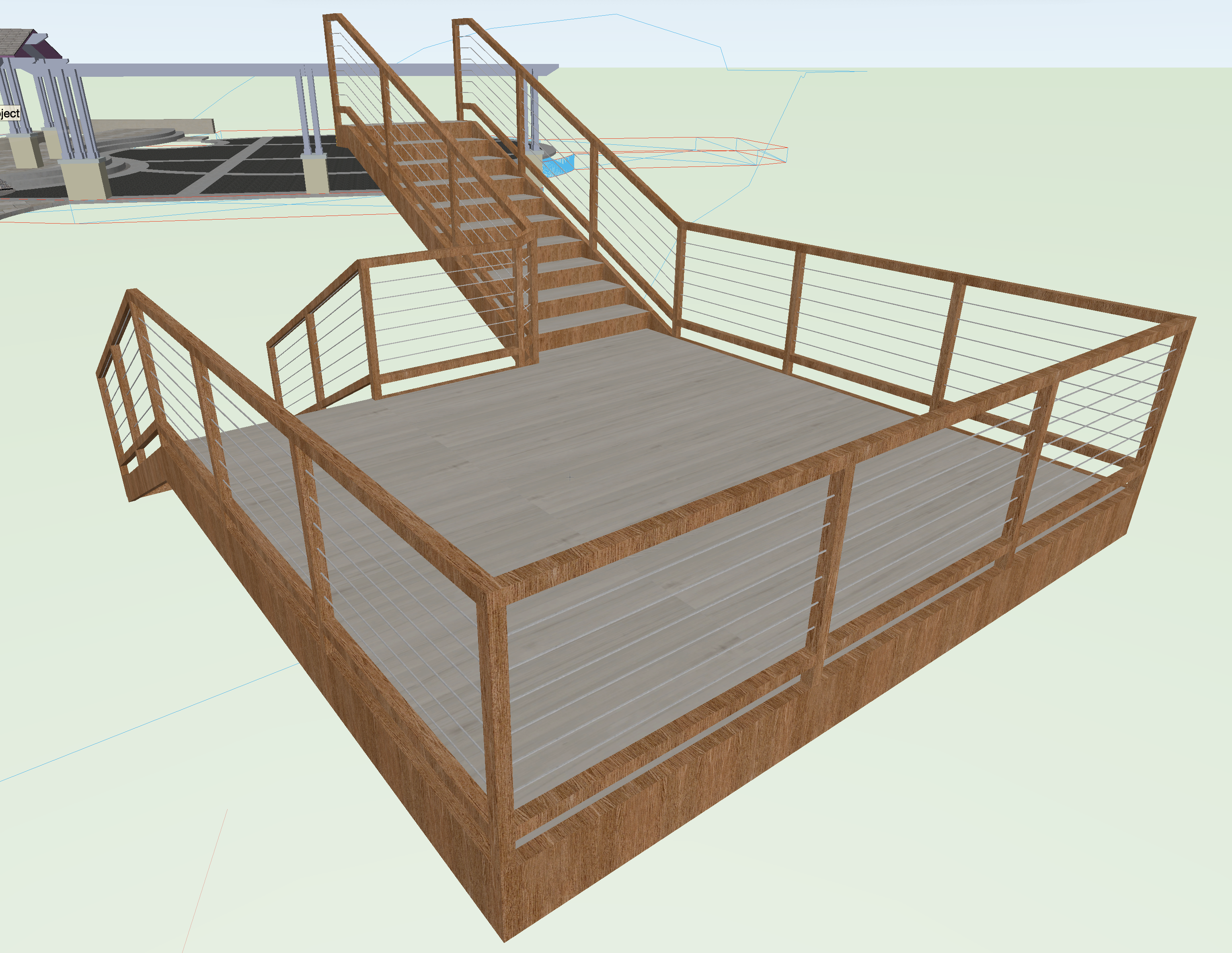
In your other thread, I mentioned I build decks just like any other architectural element and by using a variety of tools. I don't think you are going to get anything beyond that from Vectorworks staff. My advice is to learn the tools (wall, slab, stairs, railing, etc.) and put them into use. Decks are basically just buildings without interior cladding and insulation 🙂 Also, don't be afraid to hack the tools we have and use them inappropriately. Example: I use the site modeling tool for all kinds of deviant purposes to quickly generate irregular surfaces, and even building roofs on occassion. Here's a fairly simple hack.... If you are doing simple rectangular decks, the stair tool is actually a very quick way to generate the basic finishes and railings. You would have to add columns and structure to it, but that's pretty easy using the Columns and Framing or just simple Extrudes.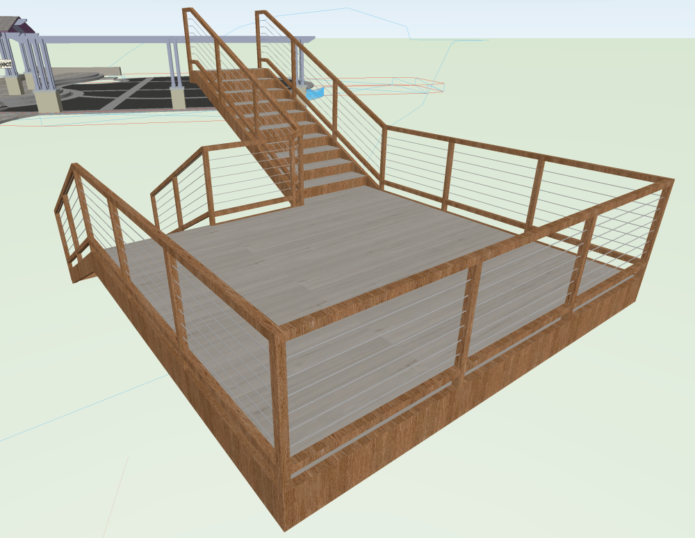
-
Candy cane stripe around Hardscape object
Jeff Prince replied to Cody Worthman's question in Troubleshooting
If you reassign a new hardscape style to the object they should go away. You can then return the style to whatever you were using previously. Doing this is a trick to reset many kinds of object that have misbehaving properties. Sometimes, when you have a hardscape that was associated to a site model or was in the aligned mode, the candy canes can stick around because the object thinks it needs to be updated, even though there is nothing to update. I think it's a bug... -
bump
- 1 reply
-
- 2
-

-
I’ve been using this program since 2016. I think there have been 3 significant graphic overhauls in that time. This latest one is the most disruptive with the least upside. It’s the equivalent of turning half the light switches in your home upside down and then reassigning half of those to unrelated functions. You can still turn the lights on, but every time you do it you have to think about how to use the ubiquitous switch for its unique situation. Sometimes up turns on the light, sometimes down. In one room, the switch turns on the air conditioning, in another it opens the garage door. The last time I protested is when they updated the icons to have an overly 3D look. Now the pendulum has swung in the opposite direction to the point of making them even harder to distinguish. That’s a lot of changes to icons in very few years. That makes it hard for people to learn the program and antiquated training materials. I don’t mean to be overly critical, but this doesn’t appear to be the work of an experienced UI designer. The human interaction side of things has seemingly been ignored. Hard to see, hard to find, increased movement needed to access common tools are not improvements. A few releases ago, the redesign of the Color Selector to eliminate the color wheel is simply criminal. To be fair, the creation of the Smart Options a while back is a great example of good UI design. we get it, software changes over time, but a lot of these changes in recent years feel like introducing a new color to an old jalopy that really needs a new motor.
-
@Ryan Russell still just curious, what design software does all of that? Perhaps you have identified a pathway to riches… you could develop some plug-ins for vectorworks for the construction market.
-
Changing user interfaces like this not only disrupts daily operations for presumably 10’s of thousands of people, but it also forces all training materials such as websites, videos, and books to be updated for a trivial reason. The net impact is staggering for no gain. I guess it keeps the training division happily employed…
-
I do not believe they have fixed that deficiency yet, but I haven’t looked in years.
-
It worked for me using your file.


-
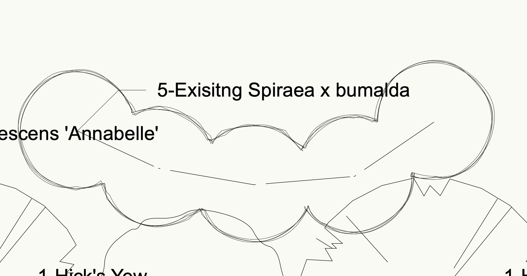
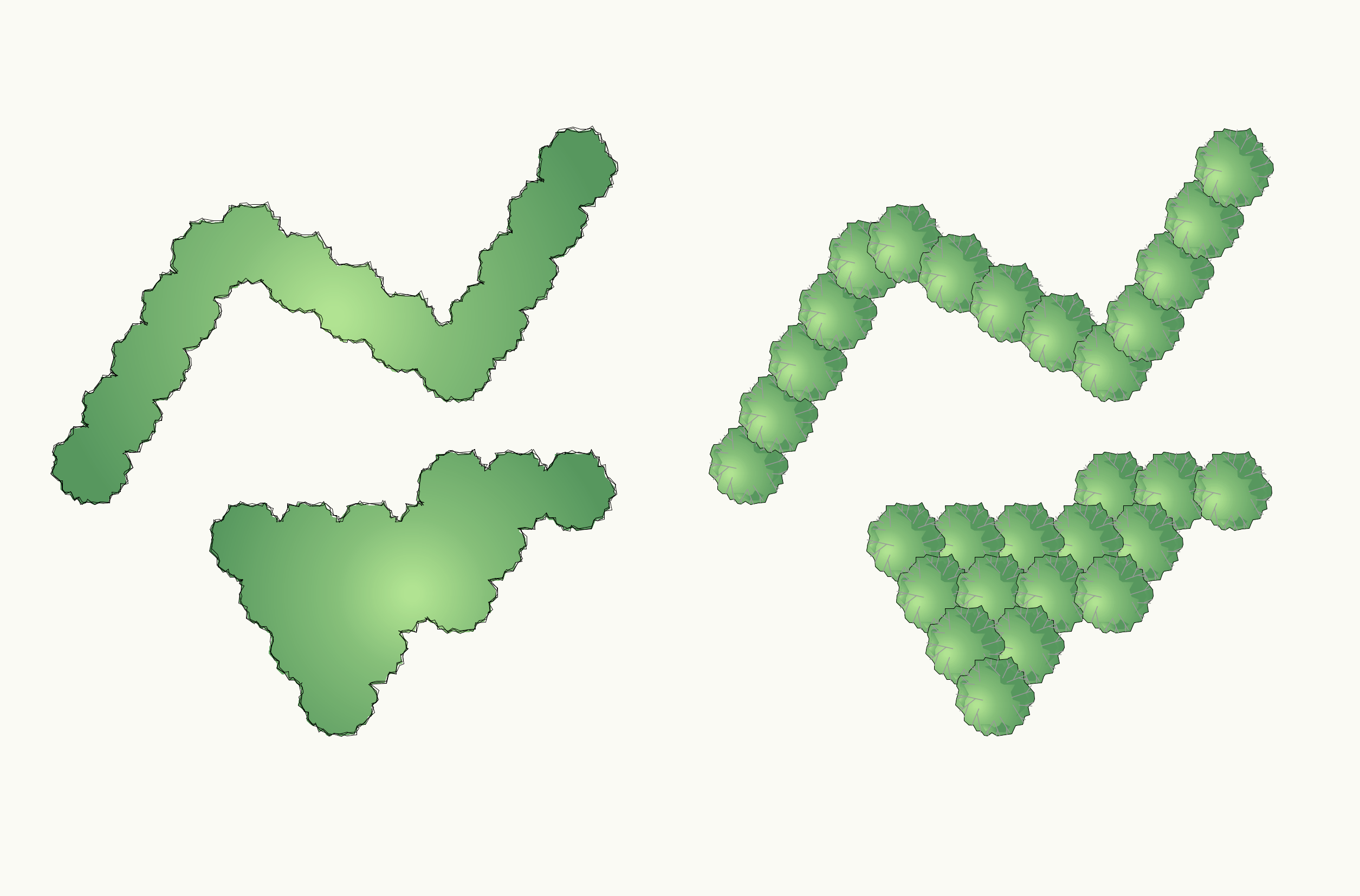
Do you mean something like this where the interior lifework of plants placed along a poly or in a mass from a poly shaped border, then yes...


-
Problem with controlling wall texture by class in VW 2024
Jeff Prince replied to EliM's question in Troubleshooting
That's interesting, I hadn't noticed that small difference. This is actually a pretty significant issue for people who are doing as @EliM. I could see a use case where you have a wall style that is defining all the components for spacing/construction method, but you want to render the outermost finish by Class so you don't have a bunch of wall styles for a change in color or texture, but not the type of component (example: different kinds of CMU walls or Stone Veneer). Still, using that methodology makes scheduling and takeoffs a bit more difficult. It wouldn't be the first time we have had to completely change the way we do things because of a small change to object behavior 😞 -
post a VWX file of your fence.
-
Problem with controlling wall texture by class in VW 2024
Jeff Prince replied to EliM's question in Troubleshooting
EDIT:I guess it is a bug in that specific use case. If you are using simple one component walls, I could see using a by class texturing methodology to move quickly during a concept phase. However, you aren't doing that, you are using complex wall styles with many components. So, you should render them "by component" and set your textures within the component settings (in my opinion). If you have a building that has multiple exterior finishes, doing them "by class" could become very cumbersome compared to managing this all with Wall Styles, and perhaps materials if you were so inclined. -
Learning about them will be a very good investment of time. There is some good information about Data Tags on Vectorworks University. Essentially, they are fully customizable tags which can get their value from different object attributes, records, and even static information. You have the ability to easily change their layout, graphic appearance, and information to include. It really feels like the direction the entire software is going and it's safe to assume built-in tagging based on an object style will die off. Attached is an example of the Data Tags for plants that shipped with 2023. Plants-DataTags vs old Tags.vwx
-
You should abandon using the built in plant tags and switch to data tags. Built in tags seem to be going away in favor of data tags. Vectorworks changed how plants behave as they refined the Style based approach. If you want to change the attributes of individual plants, you need to change those attributes to “byinstance” instead of “bystyle”. If you want to control some attributes and keep them the same throughout a document for every instance of a particular plant, keep them “by style” and make any changes via the style editor.
-
@Ryan Russell just curious, what design software does all of that? I ask because none of my architect clients go to that level of detail. They design the building and specify the systems either per building code or by structural engineer. It seems there is a lot of low hanging fruit that architects would rather have… stacked wall components, better roofs, better parametric assemblies of systems, etc.
-
Nope. Your professor probably want you to draw it by hand. The only way I know of where you can accurately fake military projection in Vectorworks is to use staked viewports and draw the connecting verticals on a sheet layer, which is essentially like drawing it by hand in the computer. The topic pops up all the time here...
-
another case of my materials being deleted? What the heck. Here's the file I originally posted: pool test.vwx
-
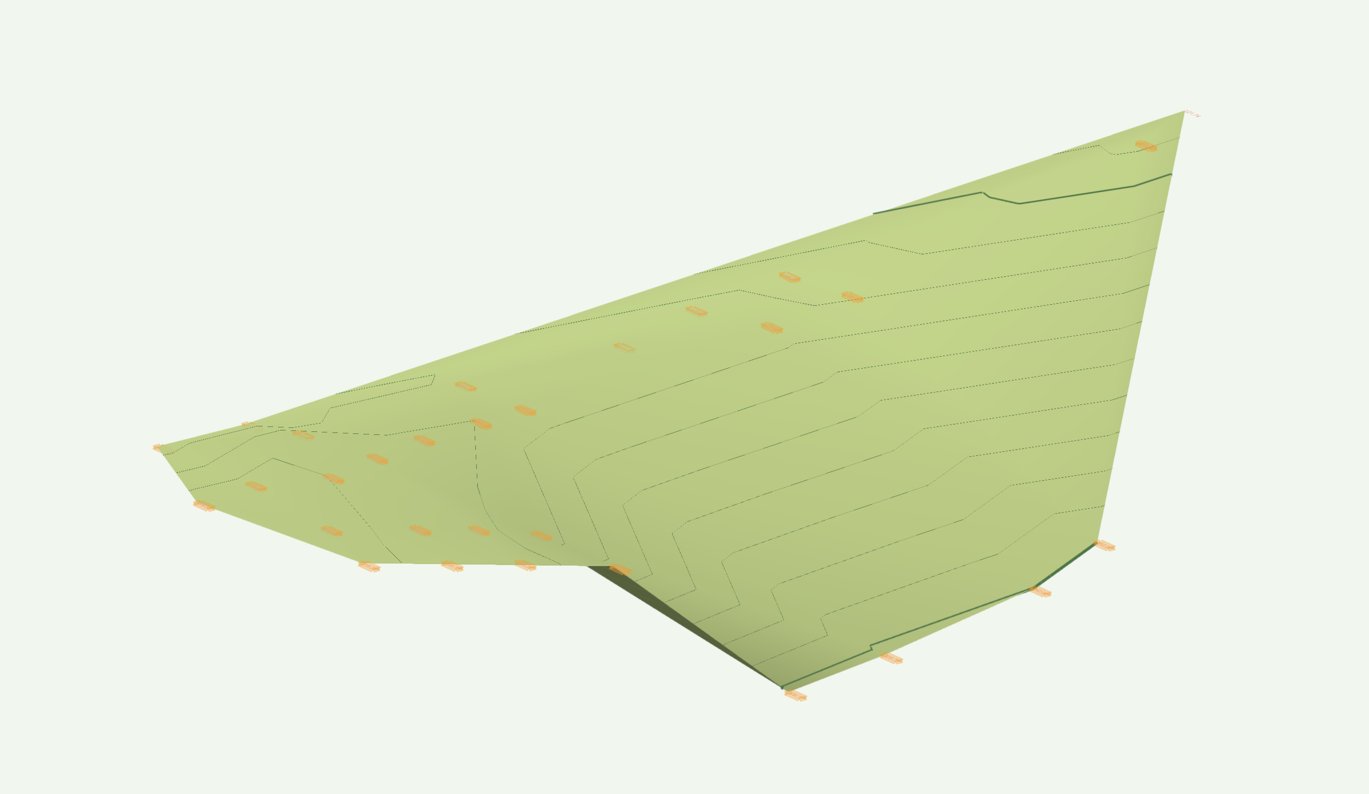
Your drawing has 30 points in it. Personally, I would just use the Stake or 3D Loci tool and place the points manually. For sites less than a few 100 points, it's fast and reliable. Otherwise, ask your surveyor for points 🙂 It took less than a minute to do this:

-
Vectorworks isn't the best tool for this type of work. However, if you must model it instead of referring to details, you could accomplish it by using the Extrude Along A Path tool found in the Modeling menu. Here's an example of how to use it on a swimming pool, but the concept would be the same for what is shown in your detail.
-
Site Modeling - Trimming Contours imported from other programs
Jeff Prince replied to Jeff Prince's topic in Site Design
it depends on the project and what is available. Surveys or scans I pay for include clean and classified points. Government data is generally ok as a starting point, but involves lots of cleanup on my end. Stuff I shoot myself with a phone or drone is pretty good, but takes time to deal with. -
It helps to know what is driving the design, or why it is shaped the way it is. Oftentimes, this reveals the easiest path to modeling it and establishing the pieces that may be required for future revisions. When I look at the image in your post, I have no idea what the design is trying to achieve aesthetically or structurally. No idea of the scale or purpose. So, it's hard to recommend a best method of modeling. Also, why are your beams all running in the same direction? Shouldn't the leftmost roof have them perpendicular to the building like the other two sides? It's stuff like this that governs the easiest path to making the form.
-
I posted some information related to @Emj86 's problem with contours here:
-
This is in response to a question in another thread, figured it should be its own thread.... Vectorworks has a hard time trimming imported contours, but there are some things you can do to make it easier. #1, set your view to Top/Plan to avoid problems with the geometry or site model misbehaving during this editing procedure. Even if Vectorworks "fixes" this in future versions, it is generally a good practice to orientate your view to something orthogonal to the edit when using automated 3D editing tools. In the case of imported contours from other GIS or CAD programs, you first need to get all your contours converted from Polygons (2D) to 3D Polys. This simultaneously fixes the issue of each contour being on a 3D plane and instead issues a correct Z elevation that occurs with some imports. Some might say this is potato/potahto, but it makes a difference when you are building site models. Next you have a choice on how to "trim" out the contours to focus on your area of interest and make the model more efficient for Vectorworks to handle. I have named these the Split Method and the Site Model Crop Method. In either case, a rectangle will define your area of interest and serve as a boundary for some editing operations. Pro tip - Make this rectangle a bit larger than the site model you hope to end up with, as this will make your contours and 3D surfaces look much nicer instead of the data abruptly ending at the site model crop. Prior to doing any edits, it may be beneficial to run the Simplification and then Validation tools found in the Site Modeling menu. This can make your data much faster to process, but will consume your time in manually refining the data. It's still a good idea because you will save time over the life of the project with each site model update or edit. Just keep in mind, each time you do a simplification, you will likely create validation issues like intersecting contours or contours that have overlapping endpoints. You will need to correct those issues prior to site modeling for the best results. Experience will give you a sense of the time commitment required to get things working correctly, do not underestimate this because bad site models can become a vortex of despair on your project if done incorrectly. Split Method - Manually trim the contours using the split tool. Concept-Use the tool you think you should, but in small steps to make Vectorworks happy. Delete any contours which to not cross or fall within the study area, you don't need them if they won't be seen and this make processing faster. Then, grab only the contours within or crossing the rectangle (which should be all the remaining contours at this point). Next, split them by doing a cutline one side of the rectangle at a time in LINE SPLIT + SELECTED OBJECT mode of the Split tool. Delete the unneeded portions of the contours and repeat your way around the rectangle. Vectorworks can't handle splitting a lot of complex contours simultaneously around a crop boundary like a rectangle. Do it in QGIS or other GIS programs prior to export if you can, it's faster and easier. Site Model Crop Method-this is a trick to get Vectorworks to crop your contours as most other programs do. Concept - Make a site model out of the entire collection of contours and trim to your desired site model boundary afterwards. First, deal with the source data as mentioned earlier.... Convert your contours to 3D Polys. Use Simplify 3D Polys to make the polys more efficient. Finish by validating the site model data to correct any problems created by the simplification process. Next, generate a site model....Switch to Top/Plan view, grab the contours, and generate the site model. You can then adjust the site model crop to your area of interest which will make things look like you want. Finally, create a more efficient site model.... Select the site model you just created. Change the Site Model's 3D Display to "3D Contours". Change the view to Top instead of Top/Plan so the site model displays the 3D contours instead of a plan view. Ungroup the Site model. Magically, you now have cropped 3D contours. Make a new site model with this cropped data and enjoy the accelerated performance of your site model. In either case, if you were a good site modeler and included data outside your desired depiction of the land, you can now adjust your site model crop and enjoy the benefits of having data beyond your crop for nice smooth contours free of cliffs and jaggies. _______________________________________________________________________________________________________________________________________ So, all this being said, you would really be better off using Points to build site models instead of contours. Contours are simply a computer's best guess as to where an elevation exists based on what you feed it. If you feed vectorworks point data, it will generate contours for you. If you feed it contours, it treats each vertex of the contour as a point, which isn't really accurate in the grand scheme of things and makes your site model very slow. Don't believe me? Here's a video of a 6500' x 6500' mountain in Phoenix I modeled from LiDAR points. Note how quickly it is to develop the site model, render with a geo image, and crop down as described above. If you take any area and convert it to contours to rebuild a site model, the resulting contours will usually generate 10x the number of vertices as the original point data if your contour value is the same. Switching to a finer level of detail for the contour interval and the number of points will become exponentially larger. That's not making your work more accurate, it's just bringing your computer to its knees for no reason. Although, if you are trying to convince your boss to pop for a fancy computer, I guess I have now demonstrated how you can make your computer look "slow" 🙂 Site Modeling tricks.mp4
-
I think that's a function of how you imported it. If you import as millimeters and ignore the invisible layers, it will pop in correctly. Vectorworks has never explained why, but I found the "5km safe zone" does not apply if you have geometry at the origin. I've had site models over 50 miles across without issue, as long as they are centered on the origin.
-
When the dwg is imported, it's converting over 500,000 objects.... How these are converted will influence how snappy the file is. It's a 2D file, but if your Vectorworks is setup to convert everything to 3D, things will slow down. The title blocks contain many things that are causing problems, delete them. Also, grab all the groups and ungroup them, place the resulting object on the layer plane. Once you delete them and purge, things should behave. I got the file to respond fairly quickly with those changes. A little deeper and you find... The Chinese characters found in the file could also be causing a problem. There are unimportant graphic orphans floating around the drawing space. There are scaled symbols, both symmetric and asymmetric. Dealing with that stuff could help too.