


Gadzooks
-
Posts
523 -
Joined
-
Last visited
Content Type
Profiles
Forums
Events
Articles
Marionette
Store
Posts posted by Gadzooks
-
-
22 hours ago, Pat Stanford said:
I would certainly recommend waiting until then to develop your worksheets
@taoist You're not going to get a better hint than that 🤐 😉
-
15 hours ago, taoist said:
I believe I need to setup a database for pricing based on size.
Width, Depth, Length and set the costs accordingly.
Can I ask what would be your pricing basis? An up to date individual 'joist by joist' cost with the whole range of (preferred) joists from prices referenced from your supplier. Or a volume basis (literally section x length x counted) - as a more wholesale approach to lumber would be priced/valued.
Either way, I see this as a bit of a 'slog' to keep up with accurate pricing. Why not just use a spreadsheet based printout of the joists to send to the builder's/timber merchant?
12 minutes ago, taoist said:EX: if length is between 10', 12' or length = 12', or if length > 10' & < 12' or length = 12'
then use cost of 12' from table.
Correct - prob best to nest a few 'IF-THEN' functions. However, how will you deal with the inevitable short cut lengths for in-fill, trimmers, service boxing and the like. Possibly best way is to not get too fixed on 'per joist as designed', but have a wider approach and amalgamate the overall timber required and then buy-in sufficient section at lengths you would prefer to handle on site. And what about waste as final % to be added?
I realise you have only chosen joisting as an example, and I don't have a clue what your end use is (eg: are you in the construction game), but (and keeping joists/structural timber as the example) I usually send drawings to suppliers for calculations/costings/delivery.
Interesting to have an estimation plan for the future - I'd be interested to see what you feel you can create with VW.
Best regards,
-
(Not the answer you'd want) - the file drags straight onto a design layer for me
For reference VW2018, Mac 10.14.6
Maybe a file with the asset already in place will help just for nw, but other than that, can't think of anything else that may help you.
Best regards
-
 2
2
-
-
I could try one of the errant jpg files on my 2018 system Nigel.
Post here or DM me
-
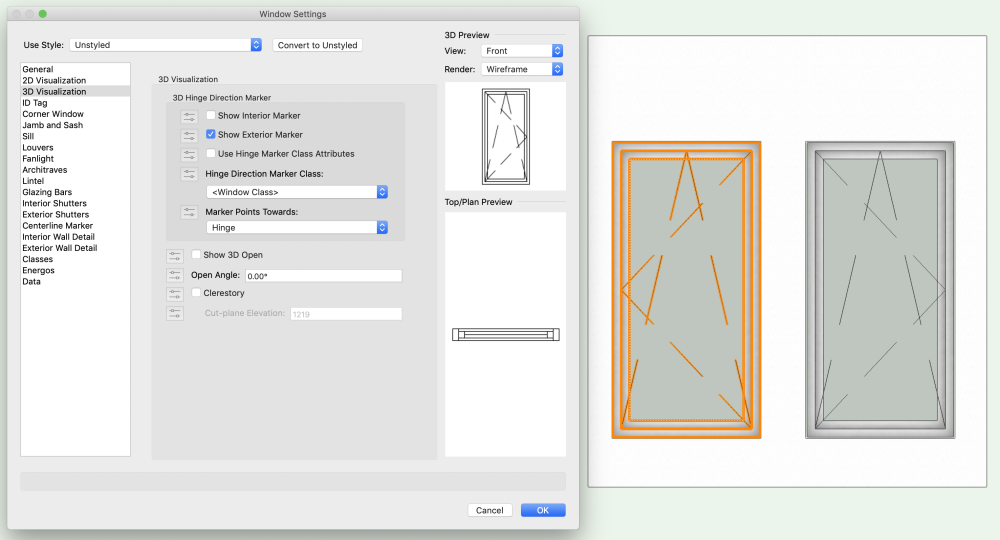
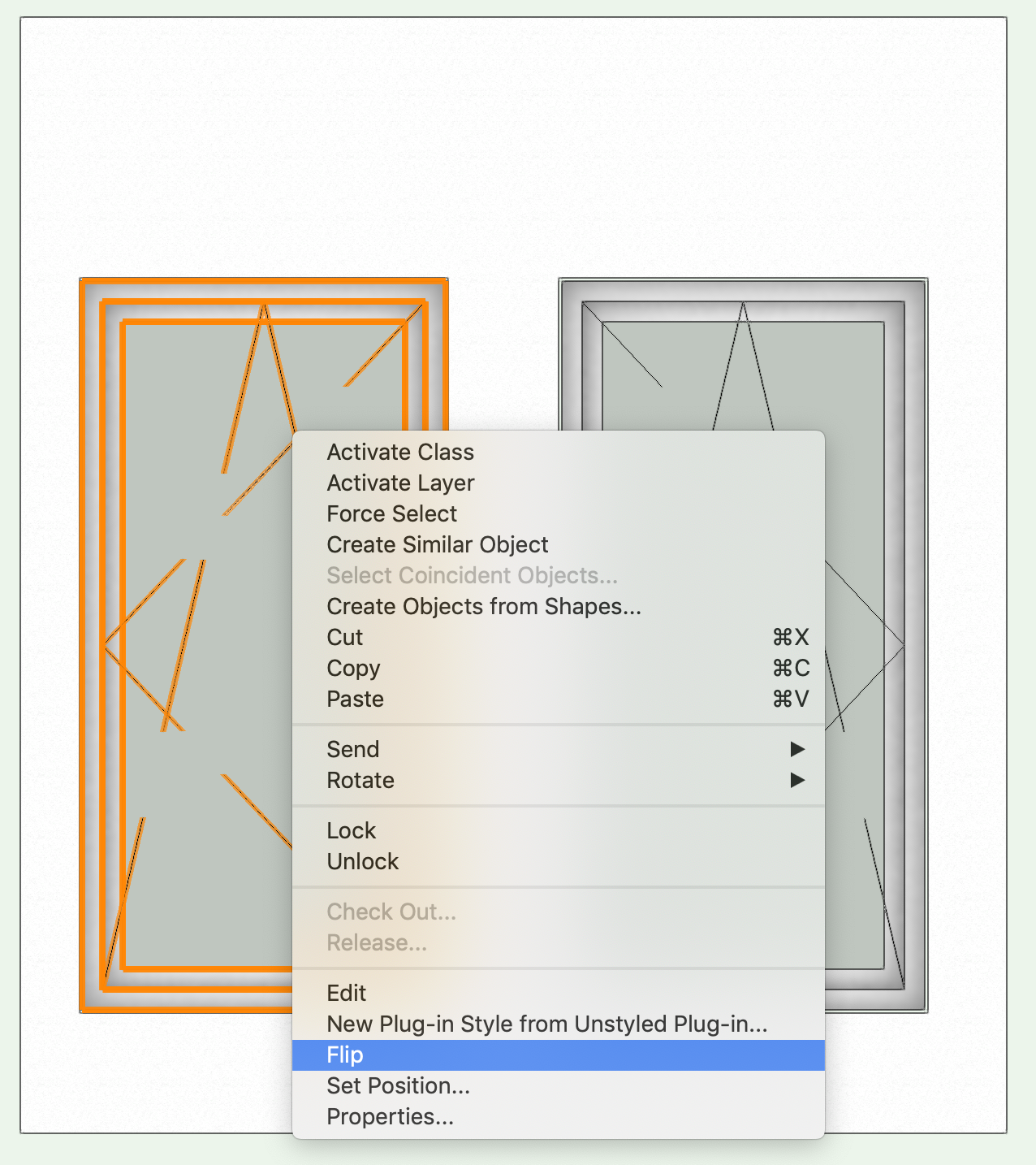
Hi @filip
Tilt and turn windows have had problems since their introduction. If you search the forum you'll find quite a few current issues on the 'performance' of the window tool having chosen tilt/turn.
Going back to 2017 you'll find right mouse provides flip to give you what you want. You could also mirror a window in plan to flip the hinge side.
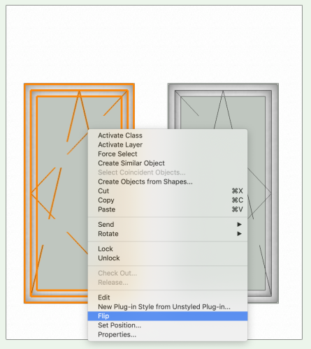
But - you'll also find the 3D preview doesn't want to show the correct choices. Just ignore.
-
On 6/3/2024 at 8:00 AM, Ragnar said:
I have drawn the house and my wife is happy with it..
Answer 1 = Have a ✅ and leave well alone 🤣
Answer 2 = Regarding the layout - I feel you are using (valuable) areas of the layout for circulation. Hallways can be impressive if large but balance the space used with the practicalities of cost/m2.
If that's what the 'client' is happy with leave it, but it might be worth adjusting the long route to the Bedroom and the route through a large cloaks area to reach a small wc.
In a single bedroomed house you might be better considering the larger shower/wc area is central enough to use for the two of you and also for visitors? You can then increase floor area in kitchen/Living room??
I'm not privy to your design reasoning nor any local codes that influence the layout, so I hope you find useful, but not upset if you have other views.😀
-
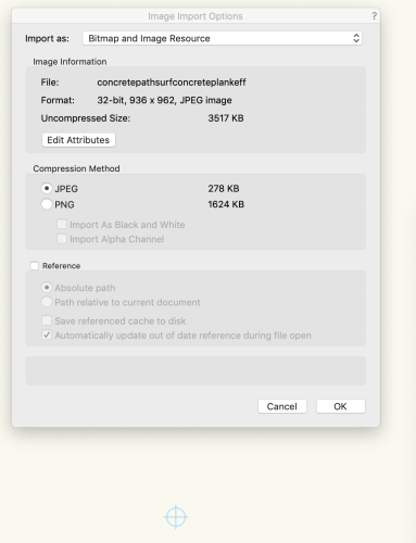
57 minutes ago, JHEarcht3 said:
VW can display transparency in its own format, but seems to be missing code for displaying Alpha Channel transparency.
The treatment of transparency is surely built into VW 2018 (my version) it won't work for you on 2013 - it will just regress the file to black background.
Unless someone will confirm, I don't think this will work. Perhaps a VW boffin will be able to confirm?
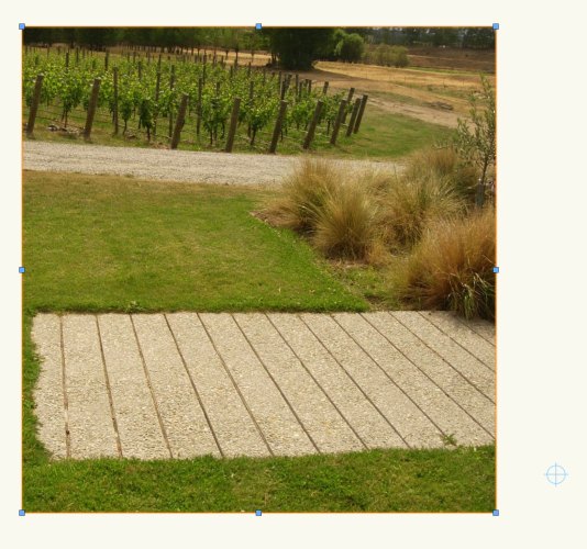
What will work is if you complete your design and, with the trees in place I'll open it for you and send back PDF's
But use PM
-
15 hours ago, JHEarcht3 said:
Is it possible to import the image into a newer VW, and then export as a .vwx file, and import it into VW2013?
Looking at the image, it is very low quality and therefore 'blocky'. Are you sure you want it at that resolution?
I can save to 2013, but I think you'll find its a lost cause and your imported file will have its 'transparency' re-applied in black.
You might be better off with a 'sketchy' form in VW with overlaid green fill. PM me the 2013 file and I'll apply something if you think that will work for you.
-
On 5/16/2024 at 4:01 PM, rudybeuc@gmail.com said:
I wish "Fit Walls To Objects" command had more options for selecting the objects to fit to.
Would be great if you could name or tag the stairs and those too would be recognised and appear in the drop down list - surely not that difficult to incorporate? But....
Time for the (usual) work-around to gaps the boffins have left.
Suggest you create a new, usually unseen 'sketch' layer that the wall will extend to, that contains only 3d planes to aid your design process. As a 'sketch' layer you may find other uses like drop ceiling surfaces, temp structures and the like.
The underside of the stairs (surface you want to extend to) is easy to mark up as a surface the 'Fit Wall To Objects' will recognise. And the stairs will be on the 'correct' layer rather than confusingly on is own.
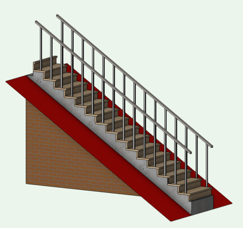
This is stairs with wall extended to unseen 'Adjustments Level'.....
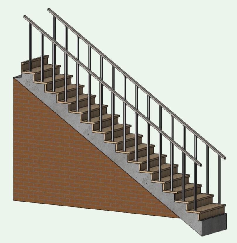
And this shows the Adjustment Layer created for the work-around.....
Hope this helps
-
4 hours ago, twk said:
My attempt below.....
Good illustration of the process @twk.
There are a few subtle pitch changes at the eaves line on @KWiley 's elevation pic. But not shown as a pitch change on the roof layout plan - Possibly needs to be finalised?
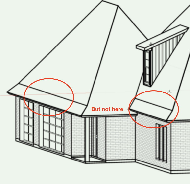
However - still easily accomplished with Roof Faces ( don't let the client change wall positions 😂 )
-
^ 2nd
-
1
-
-
3 hours ago, line-weight said:
I've ended up using the legacy "custom stair" tool
Funny how the legacy stair tool is often the best way to tackle 'architectural' stairs with a bit more style.
This is an older but still interesting stair being 'hand drawn' - Sorry nothing parametric about it, but once you have the 2D layout its not too much to adapt and develop to 3D
https://youtu.be/aj7m40TAjco?si=NMFlsPJ1pft4W-IH
-
@Dano Parke - quick question, as I can't see any benefit in your workflow. I'm prob missing something, but it seems overly complex.
Don't you end up with a handful of walls all very similar - Lets say a design based on 4'',5",6" or others very close to the same dims. Sketch layout looks ok, but you've no (quick visual) control over which wall you used unless you start clicking them in turn to find properties.
Wouldn't you do better to adopt a collection of 'most used walls'. Each can have some degree of identification for you in your chosen design use (quicker to choose and use in the layout) and then (my assumption would be) you then choose 'hide details' to provide plain grey (fill) walls for presentation to client?
Or your particular field doesn't have standard walls???
Then there's windows/doors????
-
If you don’t have the resources just Google it and find an online ‘icon builder’. There are quite a few.
(Generally) Upload a file, set your icon size from a list and use the output.
-
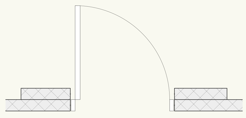
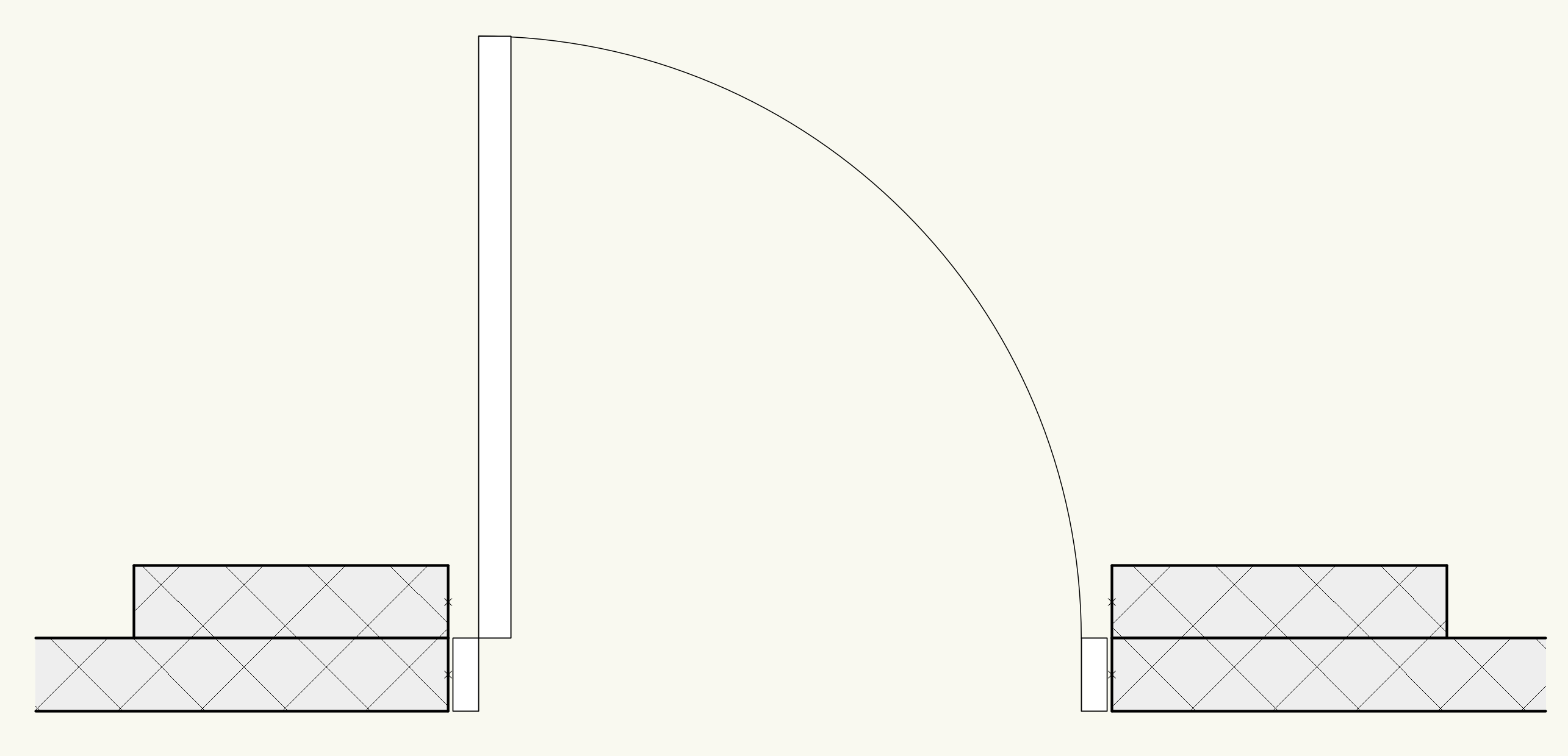
If it's a single operation, fair play to Revit.
But you could get the same effect using wall recesses to punch a starter hole in both walls then place your door more centrally if it needs
-
For an uncomplicated solution, I would use a 'door' for one wall and an 'opening' (with the same dims) for the other wall.
-
1
-
-
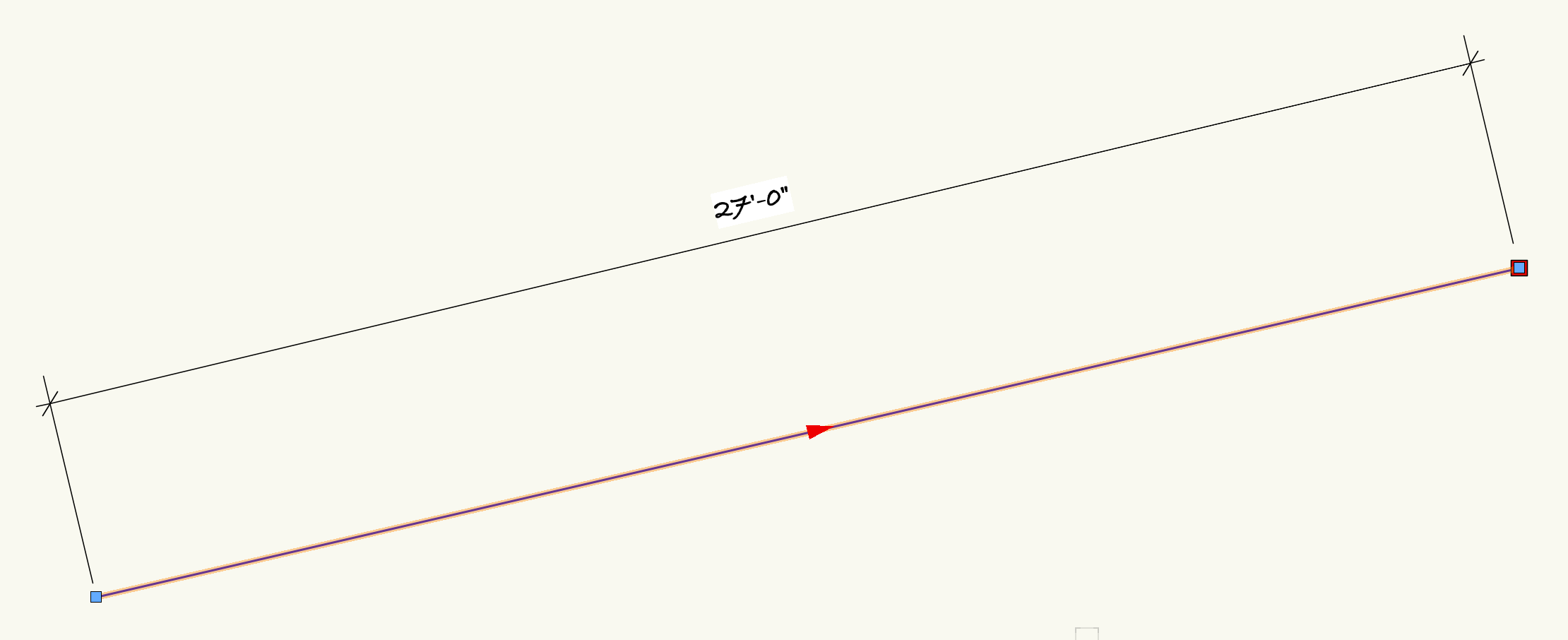
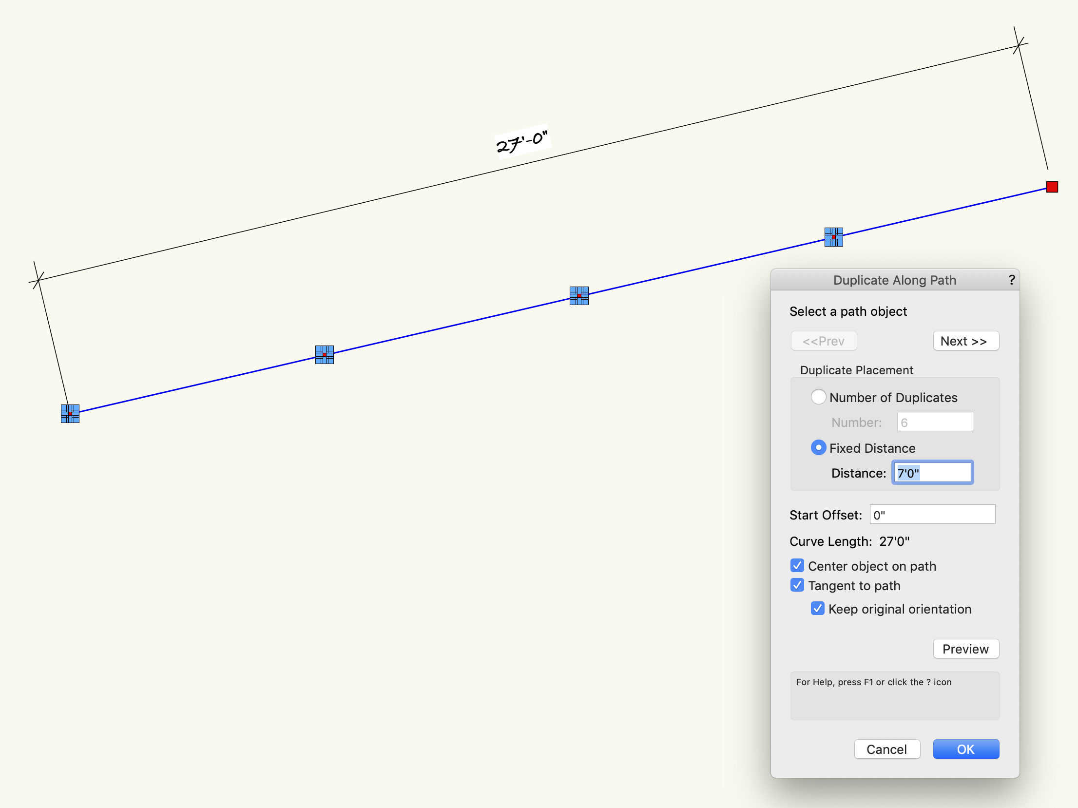
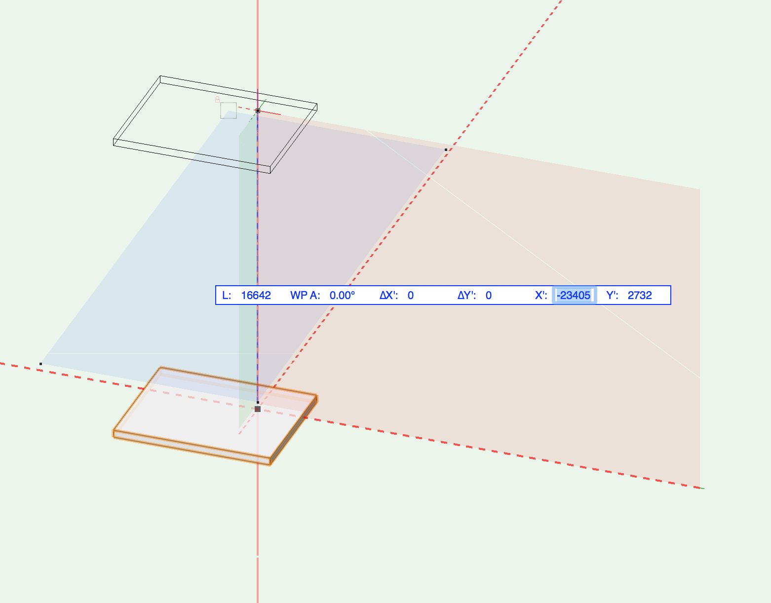
I think you are placing your object at the End of the line - probably as there is 6' remaining?.
DAP duplicates as instructed - the original is then 'lost'. The Original can be some way off from the Path, but I guess you want that extra object for your final layout.
Chose 'Show Direction' in the OIP
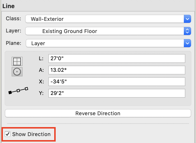
You can see where the duplications will start...
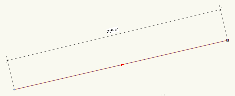
Therefore in Preview, you still see the original.

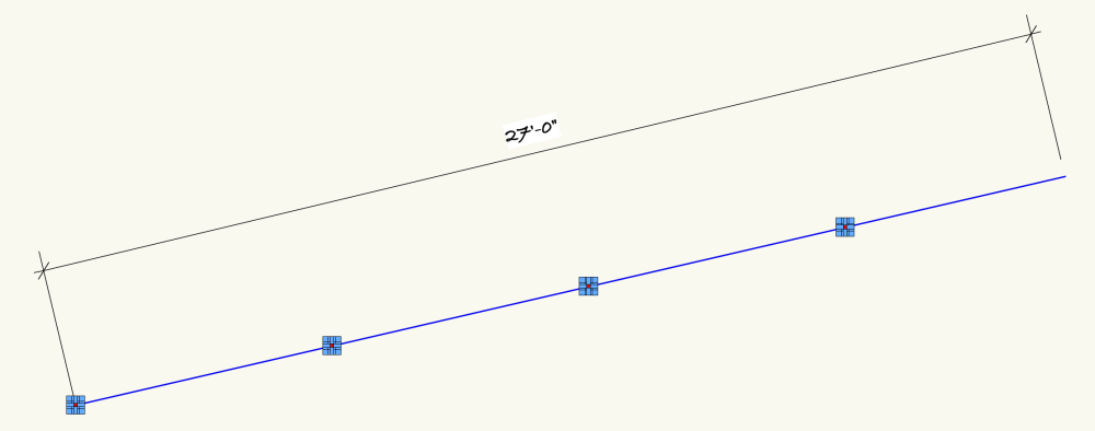
But you can see the original is then 'lost' when you choose OK
If you wanted the original to to be kept at the end of the line, copy the object before the DAP process and then Edit > Paste In Place - and there it is!
Hope I've interpreted your query correctly. You don't show a signature, but assuming you're on a newer VW than me, my screen grabs/menus may be slightly different to yours.
-
1
-
-
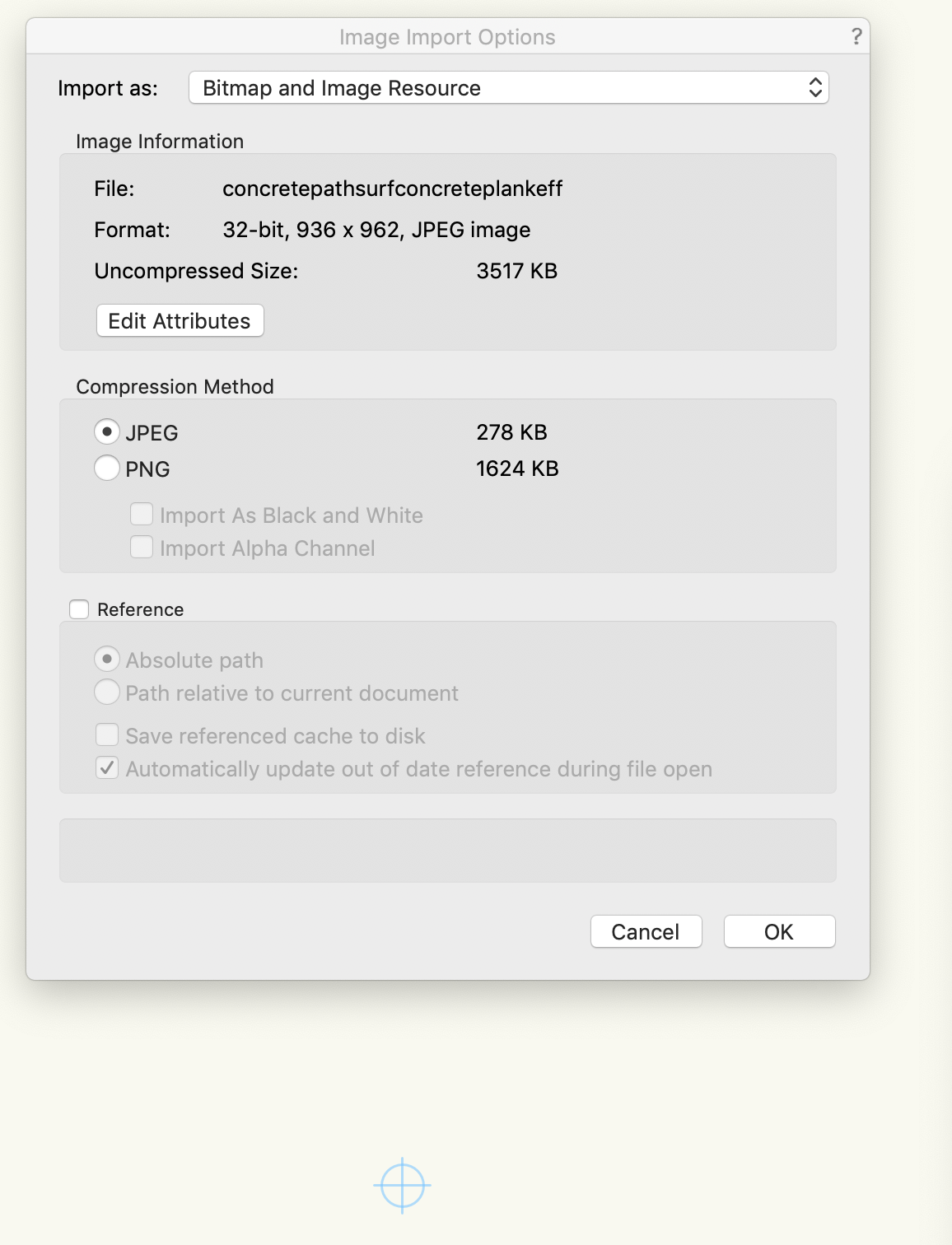
You’re not giving much background to this as it seems you don’t make any changes to the imported file 🫤.
Why didn’t you import a pdf in the first place….can you provide a better series of actions please.
(and a signature/os/version will help responses)
-
7 hours ago, line-weight said:
I have created a 3d symbol, the 3d component of which contains another 3d symbol…………..
The beast is risen - Looking to see how this turns out. So pleased that you’ve grabbed this and are looking at the options (we should all be doing that).I also use a variation of the 2d (top/plan view) and 3d (wall elevation/height) hybrid symbol for domestic switches/lighting/appliances.
Go, go @line-weight
-
1
-
-
2 hours ago, Christopher Mason said:
everything measures correctly.
Good to know your output seems ok. Looks like the final print/plotting side is suspect then. As you thought.Maybe try my earlier option on plotting out your basic scale bars so you can check over a wider area?
Can anyone else suggest a better/more thorough check ???
(Hang on Chris - we’ll get you there)-
1
-
-
14 hours ago, Christopher Mason said:
It's always off, about 6" every 25'
Are you certain of this fact? Or maybe just using a scale rule on the printout?
8 hours ago, Jonathan Pickup said:have you seen them change the settings?
Print techs should know their machines and also the options and difficulties of the software typically used on campus - but it could be worth you asking for a test print of a pdf with just a plain set of scale bars in H & V to be sure? Make them full length/width. The last thing you want is this problem to persist (stating the *** obvious!)
You're assuming your pdf is accurate? Although you don't say you have checked your own output by printing the pdf. The file you ask to be plotted may itself be the weakest link. You could import your pdf back into VW to check the accuracy.
Hope you get to the bottom of this - I've had my share of printers/plotters with 'sensitive' drivers, both the software sort and the tech sort 😂
-
1
-
-
Start to drag and tab into the options..

Is this what you need?
-
1
-
-
On 1/20/2022 at 11:40 PM, shorter said:
In order to fully coordinate your Vectorworks model with someone using Revit, first make sure your origin and their origin are in the same place relative to the model itself.
^ What Mr Shorter says.
I suggest your aim should be to agree the basic elements of 'transfer/process' before you even start the project. Don't make any assumptions that you will match expectations back/forth - have it in writing (BIM Manual or similar to outline application) if a contract depends on it. You'll then iron-out the pitfalls.
You can always swop simple files back and forth before you dive into the details. You'll find various posts here that have the 'drawing' working fine but stumble over incompatible font choice(s).
-
1 hour ago, twhitwell6 said:
Im working Vectorworks 2024
Your signature says 'Windows 7, Vectorworks 2018'


No longer a wall object
in Architecture
Posted
You chose 'subtract solids'. If you'd chosen 'create wall recess' from the AEC menu it would have retained the wall.
However I'm not sure you have that in Spotlight. And FWIW there are more direct ways as outlined above.