halfcoupler
-
Posts
461 -
Joined
-
Last visited
Content Type
Profiles
Forums
Events
Articles
Marionette
Store
Everything posted by halfcoupler
-

3d Locus not visible in wireframe Orthogonal view
halfcoupler replied to Dubman's question in Known Issues
Yes, seems to be fixed with 2019 -
Select Similar tool inside Clip Cube
halfcoupler posted a question in Wishlist - Feature and Content Requests
How about this: There should be an option in the select simlar tool settings "This selection affects only objects within the clip cube range". There are often certain objects which need to be selected out, that are in a defined aerea on a layer, but not all of these objects on a layer should be selected. Clip Cube would be the ideal tool to define this aerea. -
hi @ all ! I think there was a similar discussion here but can't find it. I have a 2d polygon on the the floor in front of a door and want to generate 50, 200 or 400 people in this area to get an idea how crowded the room is. (Actually it is a crowd in front of a theatre entrance door waiting for doors open) So what is the quickest way to fill this aerea with random symbols and random space ? Thanks much for help !
-
Exporting to pdf - vs. image file - file size
halfcoupler replied to halfcoupler's topic in General Discussion
Thanks much for the reply Jim, I often send my clients small drawings together with quotations so they have an idea of what they will get. These drawings should more be good looking than technically expicit. They should be clear renderings, not "pixellated" with as much resolution and with smallest file possible. I know that's a contradiction, but it does not make sense when they get an e-mail on their smartphone with a 50 kB quote document together with a 7 MB drawing file. I thought I could solve this with PDF files when I optimize the export options, but I guess iI will skip using PDF for that in future and will send out jpg. files. -
I have rendered a viewport on a sheet layer with 300 dpi resolution. - Exporting this via publish command to a PDF (non rasterized) results in a 5,032 KB file - Exporting this via Export command to PDF (rasterized) results in a 7,688 KB file - Exporting this via Export command to PDF (non rasterized results) in a 9,368 KB file. - Exporting this via Export command to jpg (image) file with 300 dpi resolution results in a 987 KB (!!!!) file. - Konverting the jpg file back to (rasterized) PDF via print command results in a 1,250 KB file that has the same quality as the 7,688 KB file directly exported from Vecorworks. Maybe anyone here knows the reason for this ?
-
I'm just wondering wether it is possible to create something like an object with link attribute on a design layer. Usually links can be opened by Ctrl-Click, but wouldn't it be great to give objects like symbols an attribute that opens an external link, when clicked on, so VW models could be developed as a kind of 3D information system, where people can fly over the model, click on certain points of intrest and a corresponding file or a folder opens ? Ok and here the coolest thing: What if all this could be exported as WebView so this "3D information sheet" coud be used in any browser ?
-
Yes, one of those "hidden treasures" 🤩 whats more, this way of replacement can be used the same way as the replace button in the OIP , replacing symbols as well, AND what I was always looking for, it can have a shortcut !!! I'm not quite shure, but its also seems that browsing the symbols is a little quicker than the replace button.
-
Hey, that's precisely what I was looking for ! Thanks so much !!!!!
-
Maybe I'm missing something, but afaik there is no way to select several 2D or 3D objects (rectangles, cubes, Speres, Extrudes etc.) and replace each of them directly with a symbol. Maybe anyone here has a workaround ? Maybe that's something for the whishlist ?
-
VW 19 crashes when updating older Viewports
halfcoupler replied to halfcoupler's topic in General Discussion
Usually the red hatch line (called "out-ot-date-border") only indicates that the viewport is out of date. Reason for this is: - one ore more of the corresponding design layers or classes or the viewport settings have been changed. - The document preference "Save site model cache" is disabled and Vectorworks was quit. The "out-of-date-border" can be enabled/disabled in the documents preferences too. -
VW 19 crashes when updating older Viewports
halfcoupler replied to halfcoupler's topic in General Discussion
I'm shure it has nothing to do with the grafic card or its settings. Of course I use the dedicated card. It seems that there are some incompatible parts in the old viewports (mainly section viewports) . The problem disappears when creating a new 2019 file , importing all design layers and creating new sheet layers and viewports again from scratch. But thats a lot of work.... I'ts bad that sheet layers can't be imported similar to design layers. How about having this as new feature for VW 2020 ? -
VW 19 crashes when updating older Viewports
halfcoupler replied to halfcoupler's topic in General Discussion
thanks for the help,- but neither of this works, grafic driver is up to date, creating an new user folder brings no result. There are still random crashes when updating viewports of files migrated from previous versions. Very bad... 🙁 -
I have some files that were created in VW 16 or older, updated anually until VW 18 and now I can't update the viewports in 2019. VW randomly crashes when pushing the update button. Anyone has the same problem ?
-
Worksheet calculating Spare Fixture counts
halfcoupler replied to ChadL's topic in General Discussion
Hi, sorry to disturb the "high level worksheet configuration discussion" at this point, but to my experience the amount of spare units usually does not follow exact mathematical rules,- its often a question of availability and/or transportation space. So my general "quick and dirty solution" for spare parts is simply to drag and multiply them on "spare parts layers". In that way it is even possible to generate spare part lists and/or general packing lists including or without spare, and as well make different layers and worksheets for different cases/transportation units. Maybe that helps... 🙂 -
It seems to need precise matches and ignores caps. Just stumbled over this: "fork lift" brings no result "lift" brings everything that is NOT a forklift "fork" or "Fork" works "forklift" or "Forklift" works too. not really logical...
-
3d Locus not visible in wireframe Orthogonal view
halfcoupler replied to Dubman's question in Known Issues
great ! Imagine: I get my car out of the garage where they made a general maintenanace. I notice that the driverside door does not open. Asking for the reason, I get the answer: 'Sorry we broke the key inside, but the latches have gone out, new latches will be delivered when the new car model is released. But we are glad that we sold you such a good car, it has the sensationell big amount of 5 doors. You still have 3 doors and and a reardoor, which you can use for the next half year...' 🙄 -
3d Locus not visible in wireframe Orthogonal view
halfcoupler replied to Dubman's question in Known Issues
Don't know if the reason is really service pack 4, but I cant see locus points anymore. No matter how the setting in preferences is,- they are not visible until I select them. A new locus in a new document is only visible as long as it is selected. Anyone else has this problem ? -
callout tool stopps adding leader lines
halfcoupler replied to halfcoupler's topic in General Discussion
Thanks much for this response, meanwhile I guess I found the solution: For some reason the pen opacity of the leader line was set to zero. That's difficult to find since you can get access to this button only after creation of the callout and VW seems to 'remember' the setting as general preferance. Setting it back to 100% and saving the file works. -
Don't know what happened, but I cant edit the leader lines of the callout tool anymore. I'm in SLVP annotations, inserting a callout, after inserting, the leader lines sticks horizontal and cant be edited. The callout always results in a textbox with horizontal line. Also I can't add a new leader line. After clicking "Add new Leader Line" I can draw it, but after double clicking the endpoint the leader Line dissapears. This also happenes with a new (blank) document. I thought that I have accidently changed some settings...(maybe visibility settings), I checked all options,- but can't find what's wrong. Anyone here has a clue ?
-
Thanks for all your help ! The script seems to do exactly what I need :-) I have to correct myself,- since SP 3 the problem that files do not keep the setting to 'screenplane only' after closing seems to be solved. Anyway, I still do not understand precisely when the program decides to switch to 'Layer plane' or 'Screen aligned' ignoring of what is set in the documents preferances. Is this only when 2d Objects that are in 3D plane are moved or otherwise operated ? Can't find any fixed rules for that, is it arbitrarily, or is that what people call A.I. ? 😉
-
After having again spent a lot of time correcting 2D move by point operations that were accicdently made in Layer plane modus I wonder again if this inexpressively horrible nuisance will ever be corrected. But meanwhile, as a workaround (until release VW2028, which I suppose will finally have this bugfix... 😉 ) , maybe it is possible to have a script that sets the option back to "screen plane only" by one shortkey instead of the 4 clicks 'screenplane/options/screenplane only/ok' ? Anyone knows how this could work ? Another workaround could be if this setting is somehow saved together with a saved view ?
-
Hi markdd, great! I'll check this. Meanwhile I'm wondering wether I could misuse the hoist tool for that...
-
Hi, I want to read out the 3D coordinates of certain positions in my drawing and note them on the drawing. Just at the moment I'm clicking on an object that has its center in the position I want to label, copy the x,y,z values from the OIP and paste them to the drawing beside the object. That's ok for 10 objects, but maybe anyone here knows an elegant way to do this for 100 or more objects ? Maybe it is possible to create a Marionette that produces a label with each click similar to the 3D labels in spotlight fixtures ?
-
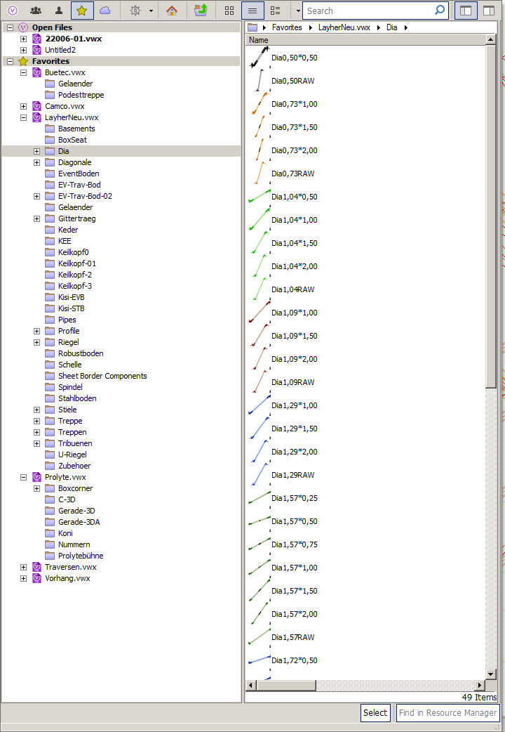
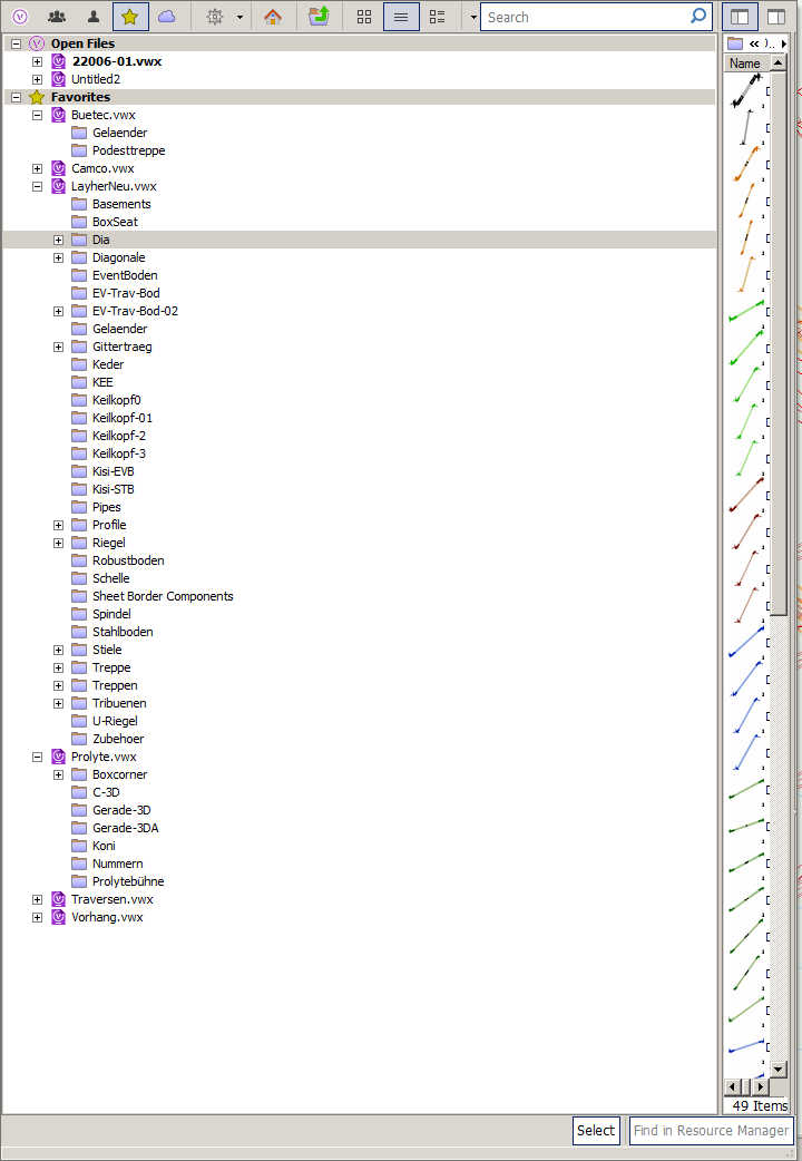
- select a symbol - press 'replace' in the OIP => the resource browser opens with minimized 'symbol pane' The pane has to be rezised to view the symbols - select symbol to replace. - repeat procedure => pane has to be rezised again. Thats very annoying when replacing a lot of objects... Is that a Windows issue or a Vectorwoks bug ?

-
How to draw transparent LED screen or mesh?
halfcoupler replied to frozenwaffles's topic in General Discussion
1.) Simpliest way is to draw one tube as extrude (3D) or rectangle (2D) and duplicate it via "duplicate array" until you have the right size of a panel, group this or create a symbol for a panel, then duplicate the panels as desired for the screensize. or 2.) Import page 2 of the martin pdf ( www.martin.com/Martin.Download.aspx?file=/files/files/productdocuments/11_MANUALS/999/UM_LCSeries_EN_A.pdf ) to vectorworks, ungroup it and use the vectorized part of the pdf as base for re-drawing 2D or 3D