
JMR
-
Posts
589 -
Joined
-
Last visited
Content Type
Profiles
Forums
Events
Articles
Marionette
Store
Everything posted by JMR
-
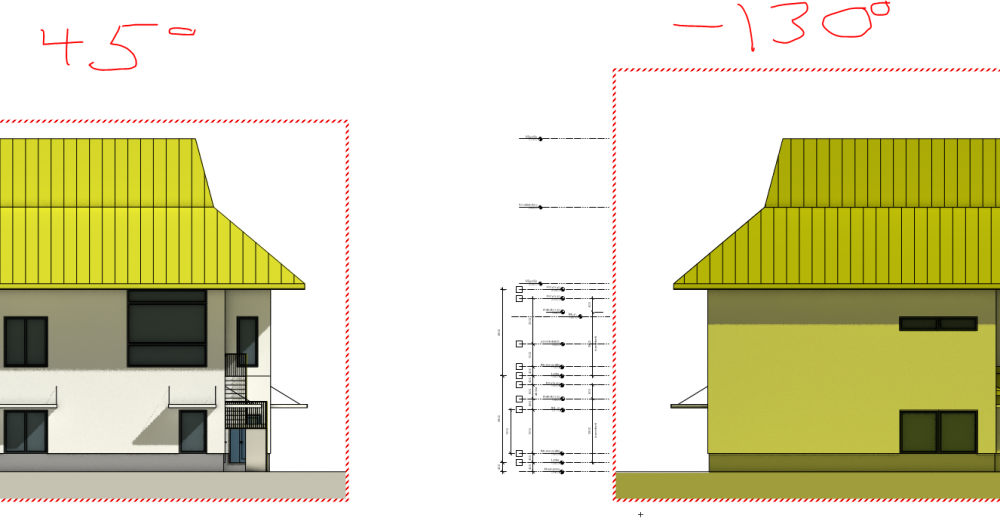
Well, the color issue is still there. Obviously something is wrong. I have two exact same heliodons, on two different classes. The other one is rotated 45 degrees in the OIP, the other one -130 degrees. Tried to set environment lighting to one. No help there. Where is the setting that causes this...it cannot be by design...?
-
Well, bummer, it seems to be indeed. You can get similar results though by creating a subdivision primitive as cube in 2018 and continue from there. Not quite the same though.
-
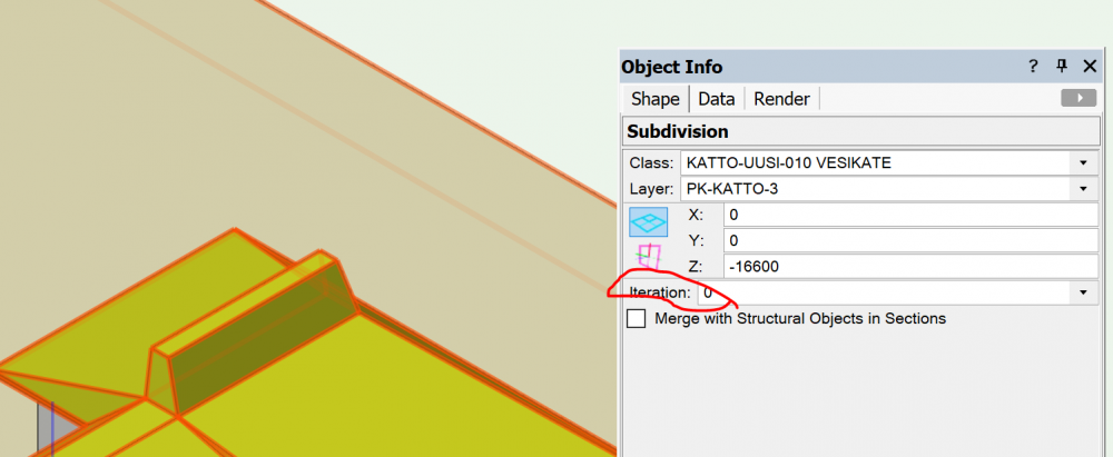
When you eg. convert an extrude to subdivison: And if you have already done it, in the OIP
-
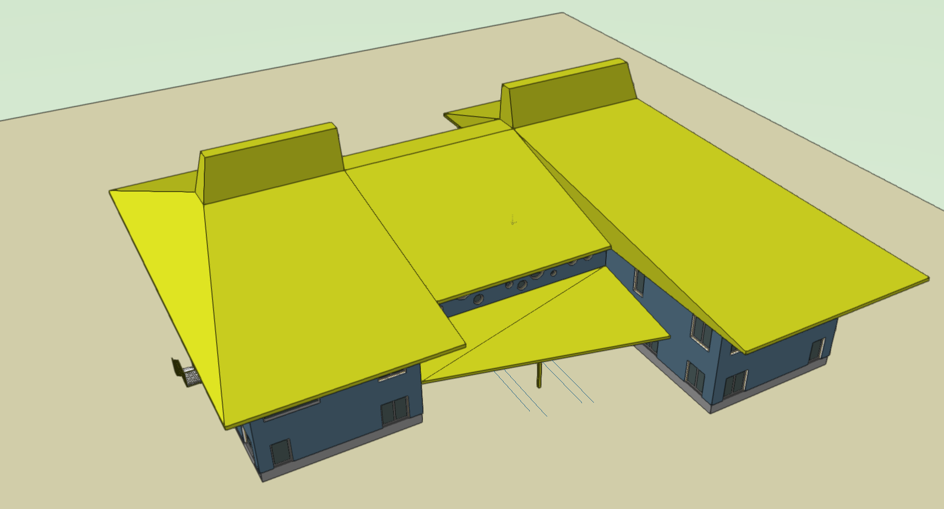
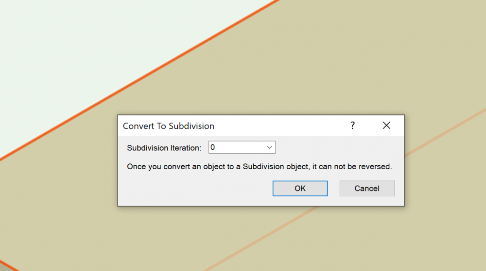
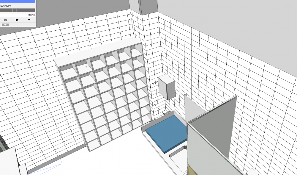
A side note on the subdivision tool: It can be used in a "linear" mode, and is actually rather powerful. For roofs, here is a "sample" method: Draw a 2d polyline describing the roof edges from above, push/pull that to some starting thickness, eg. 200mm for the eaves, the convert to -> subdivision, and set "iterations" to 0. Of course the subdivision tool doesn't have the roof tool functionality as to components etc., but for some situations and especially massing it's practical. Below is a screenshot of a subdivision roof made as described above.

-
That is very high end! Looks great. This "run of the tiles" -thing really is something that an architect has to take into account if high-quality end result is desired. If not documented beforehand, the tiles are just slapped onto the walls, the runs are erratic and taps, mirrors etc. are put wherever. The result is an awful visual mess, causing tics in neurotic architects' eylids, like me 🙂
-

Project Sharing - how to list objects within a certain space?
JMR replied to JMR's topic in Architecture
...Not possible currently...? -
That might well be the case, however please note that eg. in the previous screengrab example in this thread, the opened joins consisted of the same wall style. I can say with 100% certainty that the opened joins often consist of walls of the exact same style. This would suggest that not all the walls are checked out, even though they are of the same wall style?
-
A couple of years back we found that the built-in room finish schedule is a bit difficult to reliably maintain. Therefore we went with a custom room finish record, attached to a custom space tag. So far it's been 100% hassle-free, luckily. The built-in space data can still be used, just that we're not any longer bound to the text file defining the room finishes. Copy pasting information in the schedule is a snap now.
-
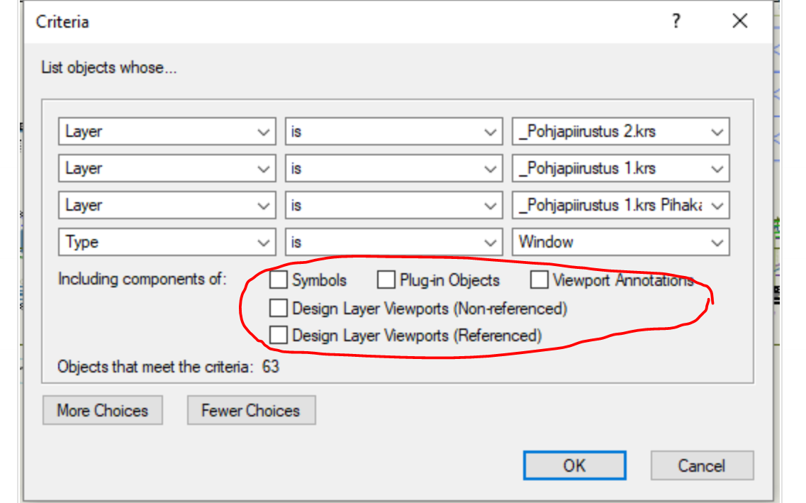
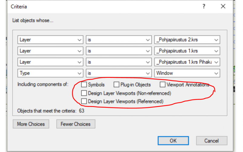
@Chris Rogers You might have included viewports and symbols in your schedule? Check these are empty (if you don't want/need them):
-
Yes I'm sure, but I hadn't applied your suggested fix at the time the unjoining occurred - the file was in it's "native" state with the stock "Attributes..." class settings. When I think of earlier instances, I'm 99% sure that we didn't edit the "Attributes Beyond Cut Plane" class - it's not something we'd have to very often in any case. HTH
-
Matt, I sent you a link to a shared directory with example files. There are states before and after, however since I was working offline this weekend there are quite a bit of steps between the files. I dug the previous ones up from backups and made a new working file based on the PF, which still displays joined walls. As to you questions, I use "automatically check out" functionality so I don't know if the program checks the walls out when editing a component class texture. I've also turned off the repeating prompt about checking out. We don't check out complete DL's any longer since the automatic check out and custom release functionality seems to work so much better (I guess it is lighter for the program to handle). Again, maybe the issue has nothing to do with component class edits - but that's the only "visible" change could guess. Now, between the example files there are other steps as well, unfortunately.
-
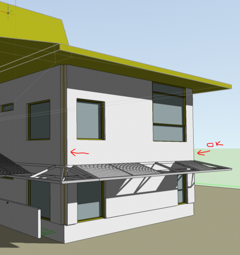
The unjoin happened to me today after I committed my file, and I think it was right after I changed the outer wall component class so that it has a texture with a surface hatch (previously none). This would further indicate it is something about classes and changes to those. Please see below. Again, curiously only some corners exhibit this even though all external walls are the same type.
-
As to Windows users, it seems Windows 10 snipping tool is being updated, the new version automatically gives a chronological file name and remembers the last directory . Still, automatic saving by the core VW program, to some subdir by project would be great...Maxwell has this feature and it's very handy.
-
Excellent work, thanks! About the cause, we haven't knowingly edited that particular class...however if the fix works, no matter. I wonder though if editing some other class the walls or components are on might have to do something to do with this as well...? Those I could say for certain we've changed in the process.
-
Hi all, A question about rendering please. Test renders that are done while working, create a handy chronological document about the design development. When I render some view, is it saved automatically somewhere, from where it could be retrieved later?
-
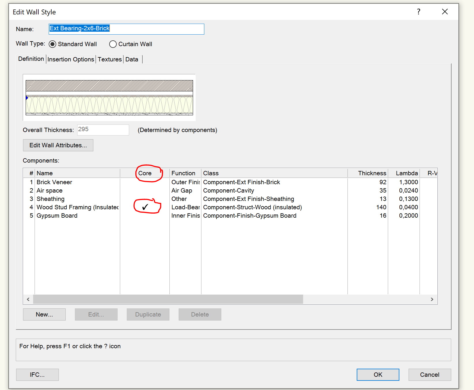
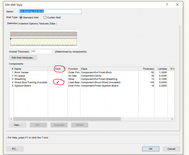
As to the wall core, please see below: The whole process of wall joining is a bit of a hit and miss. Aligned end-to-end walls can be joined with L-join, however, even if they are of the same style, they remain as two separate walls really, which is odd and plays havoc with windows and possible later changes. Do you refer to known issues occurring with project sharing, or does this happen even without it? In general, I very much agree with the above post. The wall joins are "production-critical" for an architect and it's not enough that the final drawing is "about right" - it has to be 100% correct, and the process has to be predictable. Especially since we are supposed to be doing BIM reflecting the real building. Still too often I find the component joins won't obey for no apparent logical reason. There is much room for improvement here and this particular issue is a very important one. The building cannot be presented the way the program wants it, rather how it's going to built, of course.
- 2 replies
-
- 2
-

-
- wall joins
- multi-component wall join
- (and 2 more)
-
@Acip79 You can do both, as to custom records edit the space tag via the space tool dialog, then add text and use tools->records->link text to records. Use classes to control visibility as needed.
-
Yes, we need both elevations and 3D views, so annotation is not an option. Annotation layer would also require "cutting" out stuff in front of the tiles, I think. True. There are some circumstances though where the run of the tiles is important, eg. placement of taps, mirrors etc. It goes both ways actually, since the tiles are usually set so that the extra is divided into two at the opposite ends of the wall, this determines the run of the tiles and therefore the placement of taps and other equipment.
-
In the end we did just a simple array of rectangles. The ceiling grid won't draw in anything else than plan, so that was not an option after all. It took a while to realize that the rectangles have to be a bit less than the array step; otherwise they won't be visible in the viewport. Or the lines won't. Eg. a 200mm tile needs a rectangle of 199, if the array step is 200. I wish there was an auto-updating way to do this though - perhaps please consider that the wall surface hatches could be developed a bit further, NNA? This "run of the tiles" and any repeating module stuff is very important for architects.
-
Hi all, Currently, object names do not propagate from the working files to the project file. This renders the LOC function unoperational. Bug submitted earlier. How do I make a worksheet that only lists objects within a certain space object? I can list the space number of each object with "getspacenumforobj", but I need to make a worksheet that only lists stuff in one room. Thanks
-
OT: SP3.1 is available! What I like about VW is its freedom to model and present the way you want. Archicad can be quite stiff in that sense, at least was back in 1998-2004 and 2008-2011 when was the last time I used it. Maybe it's better now. Those Bricscad Composition Plies sound interesting. I have an old licencse of Bricscad but that's from the early days when it was pretty basic. Whatever the method of component joining etc., it should be "production robust" = simple and consistent enough to withstand the daily grind of the architects' practice without falling apart at the critical moment.
-
As to the integrity of the top/plan views, I usually put these "helper" walls on an additional DL. It keeps the top/plan clean, but naturally creates some problems of it's own.
-
Indeed, those situations are very difficult. Stepped buildings can be a nightmare in this sense.
-
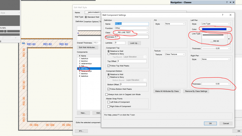
As to your visualisation; the fill and pen are not set for the REI values? That is, they are selected (apply), but the fills, colors and thicknesses have no value -> no change to the original appearance. There is some unnamed record field showing blue and black visualisation settings, which might confuse. As to another method I saw somewhere here on the forum, this doesn't use visualisation as such: Make a class for the REI text visibility control (an on/off switch) Start eg. with the stock "Gas line" linetype, make a copy of it, and replace the text with desired text (REI 30 etc). You can fiddle with the positioning and size of the text later to get it where you want, within the wall. Create a wall style that has one extra component for the REI line. Remember to set the class properly, and colors as you wish etc. Duplicate this wall style for other REI walls, change the used line type accordingly Now you have wall styles including visual representation of the fire rating, that can be turned off where desired. Within viewports, you can override the text size settings if necessary, maybe use a duplicate viewport on top with only this class visible if you want to leave other texts at original size.
- 1 reply
-
- 1
-
-
- tile
- fireresistance
- (and 3 more)
-
The wall joins are mighty important: The is no real BIM unless they cater for all possible real-life joining situations. Draggable components (in x,y,z) would be great, editable just like polygons. That would fully reflect reality. I don' know if any of the architecture cad packages can do this properly. NNA, early bird gets the worm.... 😊