


line-weight
-
Posts
3,755 -
Joined
-
Last visited
Content Type
Profiles
Forums
Events
Articles
Marionette
Store
Posts posted by line-weight
-
-
25 minutes ago, Kevin K said:
the actual 3d roof rafters. I know some would consider this extra work, but honestly it does not take that much more time, PLUS, by creating the actual roof rafters, they all show up correctly in sections....you don't need to annotate the living hell out of the sections to show the actual rafters. That said, this is just my preferred methodology. I even include the framing in my working drawings. The contractors and builders really appreciate that, so at a glance, they can get a good idea how to frame the roof, etc.
I am not suggesting that everyone should adopt it. 🙂
That's exactly what I do: it also helps me get my head around what's going on structurally.
-
While we are on the subject of roof faces:
Is there an inconsistency in the way class visibility works, compared with floor slabs and walls, or am I doing something stupid?
For example: if I have classes:
object_wall
object_roof
object_floor
material_A
material_B
- Then I have a wall, with 2 components, one is assigned to material_A and the other to material_B
- I put the wall object in class object_wall
- Then I set class material_A = visible, class material_B = invisible, class object_wall = visible
- I set the wall object to render by component
- Then what appears is the wall, but only with the component set to material_A actually visible.
- Of course, if I set the class object_wall to invisible, nothing appears at all.
But if I follow the same procedure with a roof face object, something different happens.... the component that is supposed to be invisible is visible.
Is that something that someone else can replicate?
-
@Kevin K I think it comes down to whether you want a tapering layer in the buildup. If the roof you describe was built up in such a way that the fall was generated by, say, tapering insulation, then it sounds like the slab drainage method would be best. If it were built up with some kind of rafters at a slight pitch and then a false ceiling, perhaps the roof face method (plus something else for the ceiling) would be better.
-
 1
1
-
-
I posted a file on the thread that I started 6 months ago. It is still there and available for anyone at VW to enter into the bug submit process, if they find they can replicate the problem, as it has been for half a year:
-
17 minutes ago, Tom W. said:
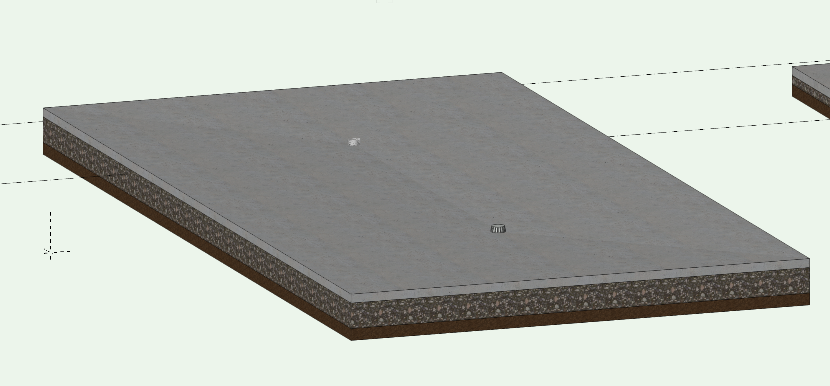
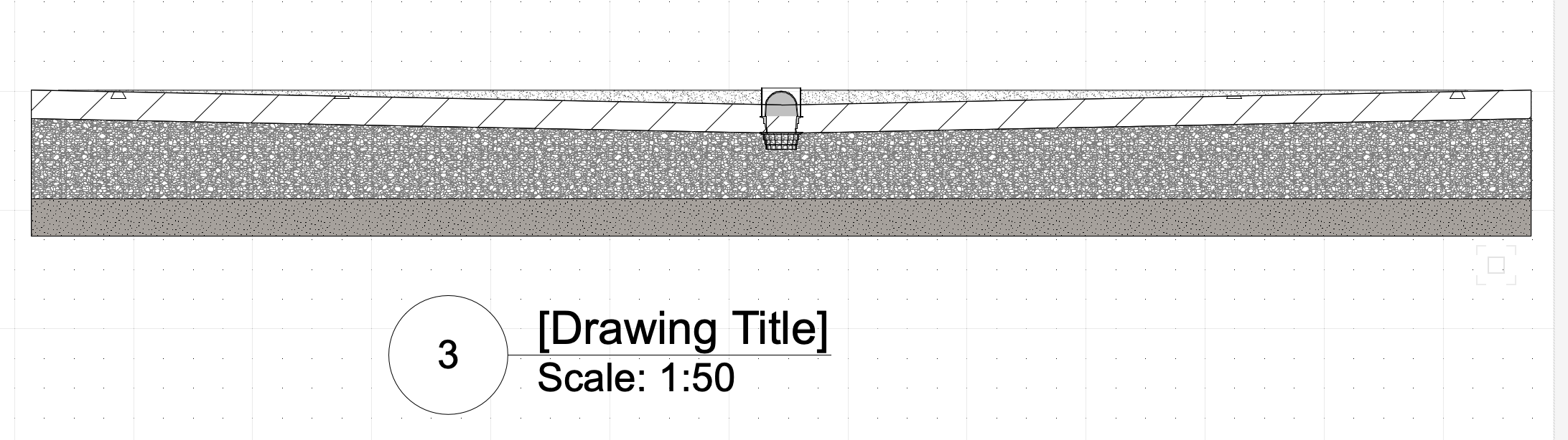
Do you mean for a flat roof? If so yes that's what it's designed for: to put in the various falls + drainage points.
Or for yard areas where you have a similar arrangement of falls/drains.
Or factory floors with floor drains.
This kind of thing:


But as I said in the thread I linked the drainage symbol component doesn't really work
However I should say this is just from messing around with these tools, I haven't used them in proper projects.
Does it limit you to a flat underside? So it suits flat roofs built up on truly flat structure, where you introduce the fall through tapered insulation or similar - but not where the structure itself is pitched?
-
1 hour ago, Helm said:
As to paying extra for an outside rendering program, in a busy office the time/money saved or the cost of using an outside rendering service more than makes up for the price of it.
For those of us that are small, perhaps one-person operations, this is not necessarily the case. In a bigger office with several employees and several jobs on the go, a license for a rendering programme can be shared around and maybe be in use most days.
For me, depending what stage projects are at, I might not really use renderworks at all for weeks or even months at a time. The calculations might be rather different.
VW has always been attractive to the smaller operator because of its price. At the moment, what I pay for VW covers my basic drawing plus rendering needs. If it becomes necessary to pay for a 3rd party applictaion to do rendering, effectively that's bumping the price of VW up, and that new "real" price would have to be compared to alternatives. Maybe VW would still come out best value compared to competitors, or maybe it no longer would.
-
1
-
-
I've never really tried the slab drainage tool - what advantage does it offer over the roof face tool?
The things I find useful about the roof face tool:
- it can give me a multi-layer buildup
- its outline shape can be quite easily edited in top-plan view
- it can give you an extrude-type object with vertical edges
- it's quick and easy to adjust and keep track of the pitch, and Z reference
These things are all advantages over using solid-modelled objects. So, even though the ability to tune the edge offsets is a big limitation (as are the problems with joining faces) it is sometimes quite useful... particularly in the early stage of projects (means that I can quickly work out the implications of different roof pitches etc) and I do sometimes use it to a limited extent in construction level-drawings, sometimes overcoming the edge problem by having a roof buildup up actually made up of a group two roof face objects, one dealing with the outer parts and one dealing with the inner parts.
But can the slab drainage tool offer the things I list above, plus something extra?
-
1
-
-
Agreed that having RW built in was a true added quality.
I could live with a decision that RW has become outdated, and hence we move to a different but fully integrated rendering engine. But would feel a bit disgruntled if it relied on paying for third-party software, while the price of VW remained the same.
-
3
-
-
On 12/11/2020 at 7:43 PM, Tom W. said:
Hi @line-weight But what was not so good was the fact that the edge conditions applied to all of the roof edges at once, which would be fine if you had a hip roof bearing on identical walls on all sides but not so good if you had a gable roof where you wanted the components to behave quite differently at the gables to the eaves. This is from memory I've not used it much I could be wrong.
yes - this pretty much matches my experience - if I remember right. The fact that you can't have it behave differently at gables/eaves makes it useless for 90% of real life situations.
-
Same here, for the most part. There are certain buildups where the insulation is outside the rafters and in those cases it would be nice to be able to use the roof face object for multiple layers. But probably it would become infeasible anyway at edges where some layers need to be set back relative to others.
-
20 minutes ago, Kevin K said:
Yeah,I have had the same issue and could never actually get it to resolve the connection.
my workaround was to change ever so slightly the roof thickness on one of the roofs so they met up acceptably.
Not the best solution, but it did work.
An entirely unacceptable workaround for anyone wanting to use it in accurate construction drawings, of course.
-
1
-
-
24 minutes ago, Stéphane said:
Might have found the beginning of an explanation... It doesn't work properly when you connect a flat roof (0.0000000°) with a tilted roof. When I fake the flat roof (0.00000001°), it works better. I say "better" because there is still something weird happening but I cannot exclude it's a design issue. @line-weight, does your issue (the post you linked) involve a flat roof ?
No, my problem in the other thread did not involve a flat roof. Also, the test that I did today was for two roofs, one 30 degrees pitch and one 15 degrees pitch, and it did not work.
-
Right, so it looks like it's yet another dysfunctional tool, and a problem that has persisted through at least 4 releases of VW?
Can anyone from VW confirm whether it's ever been reported as a bug?
-
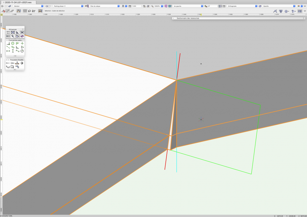
Hi @Stéphane. I think "dual object connect" is the correct one to use. I think you are doing this correctly.
I have just done a test and I get the same result as you do: I get a vertical join, when it should not be a vertical join. This is when I am using this mode:

So, either we are both doing something wrong, or the tool is not functioning correctly. Maybe someone else can help.
Which version of VW are you using? I am still using VW2018.
-
1
-
-
This is a problem I had with this recently:
-
I think you want to use the combine/connect tool using the left-hand mode (see the two options with the red line shown)
I've found this tool not always to be 100% reliable connecting roof faces though.

-
1
-
-
9 minutes ago, Kevin K said:
Ok, now I am much clearer on the big picture of what you are doing, now that you have explained things in a bit more detail.
I had thought the slight slope in your object was unintentional ! Silly me!
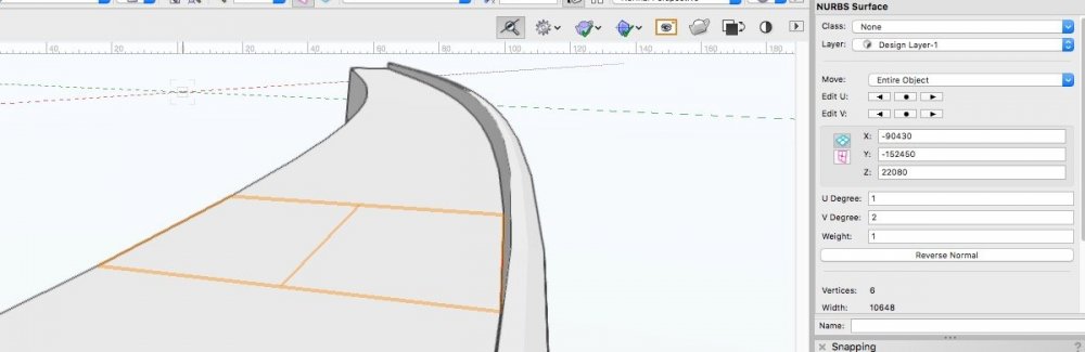
And yes,, you are correct in that you can’t create a nurbs surface directly from 3d polys, but.....if you have a nurbs curve, there is an option to create surface from curves option. I use it quite often. You CAN convert a nurbs curve from a 3d poly, however, then convert surface from that nurbs curve. It does get a little finicky at times if your nurbs curve(s) are complex.Ah! In the 3D power pack tools, I see. "Create surface from curves".
A classic bit of VW user experience design that - give you a "convert to.." menu with lots of options, but then hide one of the actual options available, in another menu.
-
1
-
-
3 hours ago, Kevin K said:
First, the main difference between nurbs curve and nurbs surface.....nurbs curves have no solid mass. think of it as a polygon with a none fill.
curbs surfaces do have mass. You can give them a solid fill as well as a few other options like extruding them by choosing the shell solids option.
On this, I've found this video quite helpful in understanding better what a NURBs surface is, and how to create one:
As far as I can make out, it's not possible to directly convert, say, a 3d polygon to a NURBS surface, only to a NURBS curve... have I got that right?
-
@Kevin K thanks for the responses.
What you have done - splitting the object into two parts, is essentially what I have ended up doing, because it makes it easier to do the kind of edits I want to do.
I should explain that the slight slope on the object is intentional, and it's this that makes things tricky, because it means that the top surface is not all on one flat plane. The slope itself is not even - it's a gradual curve in elevation - and again this is intentional and necessary to model.
I have understood most of the problems I've been having with this object, thanks to a little bit of behind-the-scenes help from @axhake. Some are due to the way I generated the original object (firstly as an EAP and then as a lofted solid) and things can be made cleaner by ensuring that the profile object is perpendicular to the path.
But there's another issue going on as well, which is to do with the faceting problem, and it means that to make things work, these objects (which are modelling railway viaducts) have to be generated using a segmented path rather than a smooth curve. The faceting problem, unfortunately, is not solved by changing the OpenGL settings. This issue is discussed in more detail on this thread:
Going back to my original question in this post - and for the benefit of anyone reading this with the same question - the answer is that you can create a solid from its enclosing surfaces simply by drawing those surfaces as 3d polygons, and then using the "add solids" command. This I didn't know - I might have expected nothing to happen because 3d polygons aren't "solids" to me, and/or maybe I'd have expected to get a hollow object. But it turns out this creates a properly solid object. Something useful to know for the future.
-
2
-
-
14 minutes ago, Kevin K said:
Sir line-weight
Geeze, what a post to wake up to! 🙂
Before I put in my 2 cents,
1) I noticed that the object in your file is a generic solid....was there a reason you didn't just leave it as the original objects?
2) IF I understand the basics, you just wanted to have that parapet object(above your red line) as a separate object??
3) did you consider simply doing an extrude along path for the parapet part?
As is often the case, there are several ways to accomplish things in VW, but....there is usually one best way...meaning less tweaking and mouse clicks. Not sure exactly what that would be in this case until I mess with the file.
Pat S usually has a good handle on all things VW, so I see he offered up a solution.
1) How long have you got?! The answer is to do with the messy way VW deals with very gradual curves where they end up as very faceted (thread somewhere about this) so I had to convert the spline type path to a segmented one, and then EAP doesn't work (I now forget why, there's a thread on that too) so I had to generate as a lofted object instead which gives me a generic solid as the output.
2) I wanted it removed, in that case.
3) Actually, that's kind of what I ended up doing (except as a lofted profile, for same reasons above) and then the 'parapet' was separate from the 'body' which made doing the edits I wanted rather easier.
-
5 hours ago, axhake said:
Have a look at this, I created in V21 and exported to 2018 so you should be able to open OK
See if you can trim the parapet back a bit by following what I did.
Alan
Thanks - I've looked at that and I can see how you have done it, and you have done it cleanly.
However - when I go into the history of the solids, and go right back to the original object, it's not quite the same as what I see in my original file.
In mine, if I try to extract one of those top surfaces, I don't get something I can extrude (I get a NURBS surface as per my screenshot above).
In yours, I do: I am able to extract a polygon.
I'm not sure if this is the result of something working differently in vw2021 vs vw2018.
I don't want to take lots of your time on this - because it's something I have got around in a different way in the end. But still useful and interesting to understand what's going on.
-
3 hours ago, axhake said:
As you have the solid you require you could simply
1. Switch to top or top/plan view
2. Place a line perpendicular to the curve at the point you want to trim the parapet back to
3. Using the Split Tool (second mode “Line Split mode”) cut your solid using the line in (2) as a guide.
4. Using the “Extract Tool” (Preferences – Tick Create Planar Object”), select the top faces of the wall (use Shift to select multiple)
5. Ungroup and extrude above the top of parapet, then extrude the back face beyond the outside faces of the parapet
6. Use the “Taper Face Tool” to close any gaps in the extrusions)
7. Select the extruded blocks and “Add Solid”
8. Select the block with the parapet and the new block created in (7) and then “Subtract Solid”… no parapet 🙂
9. Select the two and "Add Solid" to get back to one object
Thanks for the suggestion...
Step 4 (even when I use the "create planar object") doesn't seem to give me an object(s) that I can extrude.
-
4 hours ago, JRA-Vectorworks-CAD said:
What does anyone else think about moving in this direction?
What I think is that all that would be great but I'll eat my hat if it happens in the next 5 years or even 10.
-
1
-
-
I have sympathy with what you are saying @doberman69.
Especially with things like dimensions and callouts, I often feel like I'm trying to play some sort of whack-a-mole to keep them consistent. I'm in a constant state of slight confusion about what is controlling what - is it the text style or the dimension style or the text size or the class or the default it's set to somewhere or what.
I could probably get it under control by sitting down for an hour or two, going through everything methodically and working out how best to do it all, and writing myself a set of notes so that I knew what was happening next time i came to it.
There are various things in Vectorworks where I reach a threshold of things being out of control, and do that - literally spending a couple of hours writing myself an instruction manual. Sometimes I don't quite reach that threshold - I just bodge along to avoid the pain of doing the working-it-all-out.
No doubt some of this is inevitable in a complex programme, and there may be a sound underlying logic but to me it suggests bad design, or at least it's just the result of incoherent incremental changes. I wouldn't be the first to suspect that VW has got to a point where it can't really be fixed without being rebuilt from scratch.
Sometimes I feel that the mental load of operating Vectorworks and managing the drawings is actually greater than the design work that I'm trying to use it to do.
-
1
-


How to control two roof faces intersection ?
in Troubleshooting
Posted · Edited by line-weight
re-uploaded attachment with correction
Here's an example file.
Look at the two saved views and the class visibilities for each.
One is called "normal view". One is called "should be timber only".
You can see my wall and roof face objects each are made of two components: timber layer and an insulation layer.
In the saved view "should be timber only", I don't want to see the insulation on the roof. It should have disappeared like it has for the walls.
components.vwx