line-weight
-
Posts
3,755 -
Joined
-
Last visited
Content Type
Profiles
Forums
Events
Articles
Marionette
Store
Everything posted by line-weight
-

Units and rounding: downsides of excessive precision?
line-weight replied to line-weight's topic in General Discussion
Does this mean that when you think of the thickness of say plywood, it's 0,018m in your head? And then half a metre is 0,5m or is it 0,500m? -
Multi-storey building all in one storey - would this work?
line-weight replied to line-weight's topic in Architecture
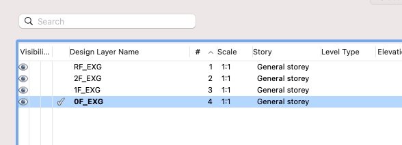
Yes... well here is the very basic setup I have made so far on the drawing I'm trying this out on.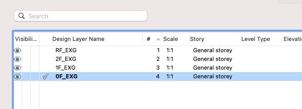

-
Multi-storey building all in one storey - would this work?
line-weight replied to line-weight's topic in Architecture
I suppose I am thinking of a scenario where eg. I am drawing up from a survey, and I have some element at 2nd floor level that I want to place offset from, say, some datum lower down like ground floor FFL, or DPC level, or window sill level or something, because that's where I took the measurement from when I did the survey. Maybe when I was measuring in a stairwell for example, or on the outside of the building. But thinking about it, maybe this is a fairly rare use case, and relating it in that way is not actually useful in the longer lifespan of the drawing. -
Multi-storey building all in one storey - would this work?
line-weight replied to line-weight's topic in Architecture
Yes, I can see that (in my system) if I change a floor level, then any walls or slabs that I've got hooked relative to that floor level will move with it, but other things (furniture, doors&windows(?) ) won't, whereas they would if I changed the layer height or if the layer height were changed along with the storey. This is not really an issue for most stuff I do which tends to involve existing buildings and therefore storey heights mostly are what they are. In fact for me when it is most useful to shuffle floor levels about is when I am drawing up from a survey and need to shift things around until they are right. For this process, I mainly get things like floor levels and wall locations right first and then they don't change, after which I add further detail. It's annoying that doors and windows can't be hooked to 'levels' (or am I missing something?) because surely this would be useful with either approach. -
I agree; this is something I would like to have too.
-
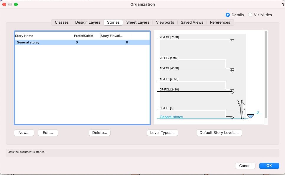
Spending this afternoon trying to get my head around storeys. As usual, VW builds the UI to make things as confusing as possible. Anyway, that complaint has been covered elsewhere. Most projects I work on have a maximum of 3 or 4 floors. I don't really need the automation to change something on 100 floor levels at once, that sort of thing. So at first sight storeys might not be for me (and that's the approach I've taken so far). However - it seems to me that the potentially most useful aspect of 'storeys' is the use of 'levels'. I'd quite like to be able to define or place objects relative to a set of defined levels. But say I am placing a wall or some other thing at the 2nd storey. For sure, I will mostly want to define heights relative to that storey's finished floor level, or ceiling level, or whatever. But sometimes I might want to define them relative to a building-wide datum. So, for whatever reason, I want to make a height relative to the ground floor finished floor level, or the roof ridge, or something. As far as I understand, I can't do that with storey levels. Is that right? I can only place relative to levels on that storey, or the storey above or below it? And it's not possible to have a "storey-less" level. Is that also right? This made me think, would it work to just have one, overall storey? It would contain all the design layers, and I would set up all the levels I wanted as "default story levels". So I'd have one named FFL-1st, one named FFL-2nd, and so on. And then any element in any layer could relate to any of these levels. This would let me give all design layers an elevation of zero. I do this sometimes already, because it means I can paste-in-place objects between layers without them jumping according to the layer elevations (a frequent frustration for me because I usually have quite a lot of directly-modelled objects). Then I would be able to set wall tops and bottoms relative to my levels, rather than working out relative to the project zero. Has anyone tried something like this? Is there something that will mean it will be a disaster? I might give it a go anyway.
-
I've just spent a couple of hours finally trying to get my head around storeys, to decide whether I want to attempt using them on a drawing I'm currently setting up. Everything @zoomer says above is absolutely spot on. He identifies all the things that are confusing when you start out trying to understand what's going on, and more stuff that I don't quite follow right now but I'm sure I would find out if/when I started using storeys for real, and I suspect it is all exactly right and will reflect the frustrations of many users. I expect most of this feedback will be ignored. Ho hum.
-
Units and rounding: downsides of excessive precision?
line-weight replied to line-weight's topic in General Discussion
Thanks @zoomer, that all makes sense. On using mm vs m - I prefer to use mm just because I "think" in mm. I think this is a UK convention, compared to some continental European countries where dimensions are shown in m or even cm. I will always think of something as 200mm long rather than 20cm long, and 1450mm long rather than 1.45m long. I have wondered the same as you though; does using mm instead of m mean that drawings start to show problems from getting too large (objects far away from origin) sooner. Currently my biggest model is about 500m in its largest dimension but drawn in mm and it seems to be ok. -
Units and rounding: downsides of excessive precision?
line-weight replied to line-weight's topic in General Discussion
Actually, fiddling around with things, I see that in fact even with precision set to 1, if I draw something 10.5mm long (by typing 10.5 into the OIP) then although the OIP tells me its rounded to 11mm, in reality it *is* 10.5mm because if I duplicate it, snap the two things together and measure the total length, it is 21 not 22. Same applies with a wall style for example - I set components at x.5 width and it looks like they've all been rounded up or down, but when I check the overall width of the wall it's correct. This now makes me wonder why there's an option to display less precision than is available, because all it does is make small errors invisible to the user. -
Units and rounding: downsides of excessive precision?
line-weight replied to line-weight's topic in General Discussion
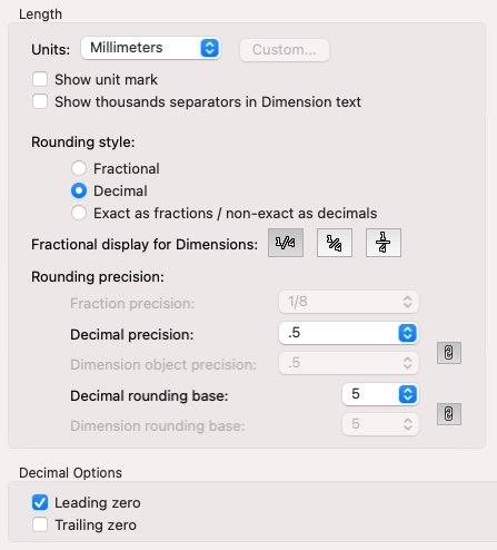
Although... I see that actually I can use these settings to draw to the nearest half millimetre: (Changing "decimal rounding base") Do the settings above, in theory, make it impossible for me to draw a line that isn't in a 0.5mm increment (unless I snap to something else)? If so, then it seems a good way of avoiding accidentally not-in-0.5mm-increment dimensions. I guess my question is still whether there are any downsides of setting the precision higher. If there aren't then it seems to make sense to do what zoomer suggests.
-
Units and rounding: downsides of excessive precision?
line-weight replied to line-weight's topic in General Discussion
Ah, thanks. That other thread outlines the same worries that I have! I've never fully understood what actually happens behind the scenes with accuracy and so on... probably some maths beyond my comprehension. For example if I draw 2 lines at right angles, each length 1 unit and then a diagonal between them, I know that's going to be a number with an infinite number of decimals, so somewhere it must get rounded up or down, but if I then add lots of those diagonals together, don't all those rounding errors add up and cause problems. Probably best just not to worry about it. Going to try @zoomer's method on a new drawing and see if it presents any problems. -
I tend to draw with millimetres as my unit, and with "decimal precision" set to 1. That's because, for architectural work you don't generally need to be more precise than a millimetre. However - there's one issue I run into repeatedly which is (at least in the UK) a standard brick is 102.5mm wide. Of course, no brick is actually exactly 102.5mm wide, but this is the dimension used for various co-ordinating dimensions, and the 0.5mm will add up over multiple bricks. It comes up, for example where I am drawing a cavity wall which is 102.5mm brick, 100mm air gap, 102.5mm brick. The overall width of the wall should therefore be 305mm. But when I make that wall style, because I can't use half millimetres I have to make it as 103+99+103, or 102+101+102 or 102+100+103 which is annoying, especially when I come to dimension things. So - my question is, is there any downside to me changing to drawing with "decimal precision" set to 0.1 instead? Somehow I worry that I'm going to start finding all sorts of things that measure 99.9mm and so on, but I'm not sure this is rational. When I come to dimension things, I can set the dimension precision to "1" (because I don't want to produce working drawings with dimensions like 104.6mm all over them) and then for any dimensions that I do want to show as eg. "102.5" I can change the precision individually. Is that going to work? Final question: if I change an already existing drawing from precision of 1 to precision of 0.1, is anything bad going to happen? Or does nothing actually change 'behind the scenes" and all that changes is what is shown to me?
-
I was in the same position as you... decided to go for the M1 and as a consequence had to go for the VW upgrade. I was on 2018, now on 2021. VW2021 is better than VW2018, but not lots better, and I only did it because I had to in order to move to the new mac. In and of itself, the amount I had to pay for the VW upgrade was not worth the limited improvements (and all the most annoying bugs and problems still remaining). Because I bought with a VSS subscription, I will be able to get 2022 as well, and so I'm going to hope that whatever it brings makes what I spent seem worthwhile.
-
Yes, that works for me most of the time, but sometimes it doesn't, and it seems to change when I come back to the computer when I've left it overnight.
-
Seems like problems related to things sleeping or not sleeping or not waking is a common them with the M1. For me, it's a monitor that sometimes refuses to come to life when I wake the machine. The problem always happens after the M1 has been left alone overnight (ie when it's been asleep for some time). I've found that I can largely prevent this from happening by (1) switch off the troublesome monitor then (2) put the M1 to sleep, at the end of each day. No idea why this should make any difference but it seems to save me from the situation where I can only get that monitor back by restarting the computer.
-
I just asked because I've realised that OpenGL can become jittery when I have a floating view pane open - this affects the main pane and the floating view pane. I think there are various problems with floating view panes...but this is a subject for another thread.
-
This wasn't when you had a floating view pane open on a second monitor by any chance was it?
-
Railing/Fence: Custom post problems
line-weight replied to line-weight's question in Troubleshooting
I expect we are shouting into the void and we'll never get an answer to that. -
Railing/Fence: Custom post problems
line-weight replied to line-weight's question in Troubleshooting
Agree with everything you say. It seems the "red" symbols need to be split into two sets; there needs to be another colour. Also, each type of 'thing' needs one, consistent, easy to remember and understand name. It's really confusing with the terms "symbol", "symbol definition", "style" and "plug-in object" all flying around. -
Railing/Fence: Custom post problems
line-weight replied to line-weight's question in Troubleshooting
This has got me reading what the official help says https://app-help.vectorworks.net/2021/eng/index.htm#t=VW2021_Guide%2FSymbols%2FSymbols.htm%23XREF_75382_Vectorworks_Symbols Am I right in saying that the bit in bold is wrong? Because for example a door style is a "red" symbol definition. But if I create a door style, which gives me a "red" symbol in the resource browser, and then use it to create a few doors in the file, then if I change the settings for that red symbol, it's an edit to the style and all existing instances change accordingly. -
Ah - thanks!
-
It would be nice to have something similar to hide everything except the objects clicked upon... I am often temporarily putting objects into groups, so I can then click into the group, and have all external context disappear, and work on just those objects I've put in the group. This is often a workaround for the various tools that malfunction when trying to select a specific face in amongst many other objects, such as the push-pull tool.
-
Railing/Fence: Custom post problems
line-weight replied to line-weight's question in Troubleshooting
Yes, exactly, the whole thing is inconsistent and confusing. Took me a while (and quite a lot of frustration) to come to the same conclusion - with the Railing/Fence tool you are only saving a configuration of settings. Nothing in the implementation helps you to understand this quickly, because it doesn't follow a pattern established by the way other tools operate. It doesn't work off an existing understanding of what a "symbol" is, it seems to be something like what a "style" is, and yet it's not. -
Railing/Fence: Custom post problems
line-weight replied to line-weight's question in Troubleshooting
How's the user supposed to know this though? When I look at the resource browser showing everything that's in my current file, there's the drop down menu where I can choose between different types of resources. I can choose, for example, "text styles" or "wall styles" as a category. But when it comes to a "fence style" it is under the category "symbols/plug-in objects". And then there are "styles" which are in a "style" folder but under the category of "symbols/plug-in objects". So in fact there are at least 3 different places you might find a "style" - in its own-category top level style folder, in its own-category folder under "symbols/plug-in objects" or simply mixed in with everything else in the "symbols/plug-in objects" category. Furthermore, the "fence/railing" tool invites me to save these settings as a "symbol" not as a style. And, for example if I right-click on a titleblock object it gives me an option to "edit plug-in style" but if I right-click on a fence object I get no similar option to edit the style ... in fact it's still unclear to me whether you can actually edit a fence "style" (which nowhere is named as such). I don't think it's hyperbole to say all this is a user-experience disaster zone. -
Railing/Fence: Custom post problems
line-weight replied to line-weight's question in Troubleshooting
Another thing that's really confusing about the fence tool is that aside from whether you use a custom symbol within the fence post settings... you can save the whole fence, or rather the fence settings as a symbol, which then appears in the resource browser as a red symbol. But it's not really a symbol, more like a saved set of settings, which to me ought to be called a "style" or something like that. To me it's unclear what exactly it is, this "symbol" that is created. I can use it as a way of applying that bunch of settings to another fence object, but I can't seem to go in and edit the "symbol" and then see these changes applied to all other instances of it. So it doesn't conform to the principles of what we expect a "symbol" to be. Another example of absolutely terrible UI design if you ask me.