


line-weight
-
Posts
3,755 -
Joined
-
Last visited
Content Type
Profiles
Forums
Events
Articles
Marionette
Store
Everything posted by line-weight
-

Point size control for Point Clouds
line-weight replied to JeremyLondonRMLA's question in Wishlist - Feature and Content Requests
Yes, well done! This is definitely the approach I would prefer for really old buildings - rather than creating the "idealised" model, because if walls are leaning/twisting significantly enough, then it does actually affect the geometry of what you can subsequently fit into it. Your method makes sense to me as a pragmatic way of extracting some of the detail into a usable VW model. It would of course be nice if it could somehow be automated, and what @zoomer describes Bricscad being able to sounds really useful. Probably we need to develop some pretty sophisticated AI before such a process could be fully automated - until then I guess there will always need to be a fair bit of human intervention in the process. Did you consider taking a horizontal slice at vertical intervals going up the building, and then trying to use some kind of loft command to generate the solids for the walls? -
That's interesting; do you just have 3 'levels' for each of your storeys? Are they chosen because they are the convenient heights to hook the bottoms and tops of your walls to? I have been using levels partly as a way of fixing various useful datums for the model (previously I've actually resorted to writing them on a bit of paper pinned by the screen) because it lets me store that info "in the file". In practice I'm finding that levels aren't really that useful for drawing the model because there are so few objects that you can set relative to them (pretty much just walls and slabs?). In particular it seems a major omission that doors and windows can't be set relative to them but really I'd like to be able to set any object's z height relative to one of my levels. I still end up getting the calculator out to work out where certain things should be, now referring to my 'levels' set up instead of my bit of paper. But maybe a spreadsheet is a good idea.
-
This raises the alarming proposition that it's possible for something worse than VW windows and doors to exist.
-
Activate Selected Object's Class?
line-weight replied to Bruce Kieffer's topic in General Discussion
This is what I get when I right-click on an object
-
Point size control for Point Clouds
line-weight replied to JeremyLondonRMLA's question in Wishlist - Feature and Content Requests
@Tom W.thanks. I normally tend to do my own surveys and one reason for this is that it seems to take as much time translating a surveyor's (conventional) 2d plans and sections into a useful 3d model, as it does for me to draw up a 3d model directly from my own survey info. Also, when measuring-up, I know what's actually important to measure. The laser survey/point cloud method is obviously very attractive if it cuts out the tedious process of physically taking the measurements... the question is whether the process of making the point cloud into a usable model then becomes an equally tedious process in itself. I'd be interested to hear how you get on with it in practice. -
Point size control for Point Clouds
line-weight replied to JeremyLondonRMLA's question in Wishlist - Feature and Content Requests
I might be going a bit off topic for this thread but what happens next with the point cloud info? Is it sufficient to generate meaningful "as existing" sections/elevations/plans? And if so, when you come to drawing whatever the newbuild elements are, does part of the model stay as a point cloud or is there a process where you have to convert it into objects that VW understands what they are? Eg those roof beams or the walls; do you convert them into solid objects at some point? -
Trouble snapping while rendered OpenGL?
line-weight replied to Bruce Kieffer's question in Troubleshooting
I have this problem particularly when in a floating view pane. Snapping becomes very unreliable in OpenGL. -
I'd quite like to try a bit of thermal modelling - nothing too advanced, just a way of adopting a slightly more scientific approach to avoiding cold bridges and so on, in the context of architectural detailing. At the outset at least, a 2d approach would be fine I think. Obviously, the more compatible with Vectorworks the better. The package I see mentioned most often is THERM - available for free: https://windows.lbl.gov/software/therm The problem there is that it looks like a bit of a hassle to get it to run on a mac, and especially my relatively new M1 mac. I've also found another package which runs natively on mac https://energy.concord.org/energy2d/index.html But that looks a little basic and not really aimed at architectural detailing. Then there seem to be various paid-for things out there, some running on the cloud, but they are all rather opaque about their pricing (which I suspect might be geared towards large corporate users). Before going further with my researches I thought I might ask here in case there's anyone knowledgable on this stuff who could point me in the right direction.
-
Additional Roof Options
line-weight replied to Kevin K's question in Wishlist - Feature and Content Requests
This looks pretty handy - not just for architraves etc but also for repeated-element wall coverings etc. I wonder if that could be used for things like tiled or slated roofs (even if it didn't give a fully accurate representation it might give something that produces better results in sections etc) -
Additional Roof Options
line-weight replied to Kevin K's question in Wishlist - Feature and Content Requests
I'll give this a go at some point, by the way. -
Additional Roof Options
line-weight replied to Kevin K's question in Wishlist - Feature and Content Requests
That's a shame ... alternatively is it possible to copy and paste-in-place a path, between one object and another? Because then you could have a bunch of profiles all extruded relative to the same path, and if you wanted to change the path you could do so in one of them and then just copy to the others. -
Additional Roof Options
line-weight replied to Kevin K's question in Wishlist - Feature and Content Requests
Nicely done! The principle of modelling things as they would be built/assembled is definitely a good one. In that example you don't get the 'seam line' problem because the panels are not a continuous material with the flashings. -
Additional Roof Options
line-weight replied to Kevin K's question in Wishlist - Feature and Content Requests
Thanks - that looks pretty handy and a potential escape from the dreaded extrude-along-path which I hate! Does it allow you to contain multiple objects (ie with different classes) within the profile symbol? -
Additional Roof Options
line-weight replied to Kevin K's question in Wishlist - Feature and Content Requests
Haven't heard of this - where do I get it? -
Additional Roof Options
line-weight replied to Kevin K's question in Wishlist - Feature and Content Requests
Yeah, I use a section or top view for the roof plan. Looks something like this for this bit of overlapping roof planes But it gives me a bunch of lines that shouldn't be there - eg the red circled ones - where the roof face meets the flashing. I've not yet worked out how I'll deal with that in this drawing - it's possible I might convert the roof faces to dumb solids when I'm happy everything is correct, and then do some solid additions. By the way, one of the reasons I rejected the hybrid-with-top/plan workflow is that I kept having the same sort of problem - a seam where a hybrid object joined something else.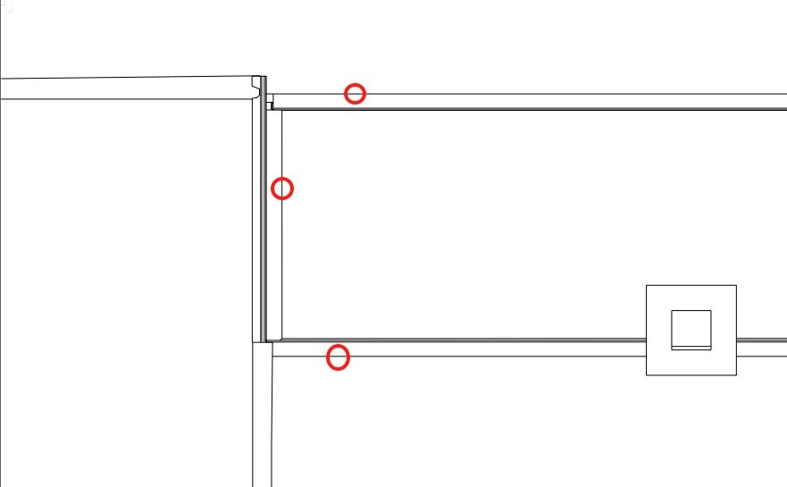
-
Additional Roof Options
line-weight replied to Kevin K's question in Wishlist - Feature and Content Requests
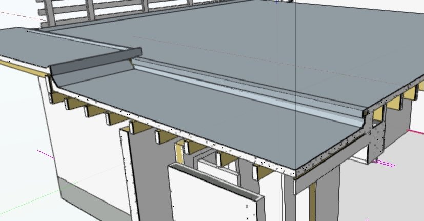
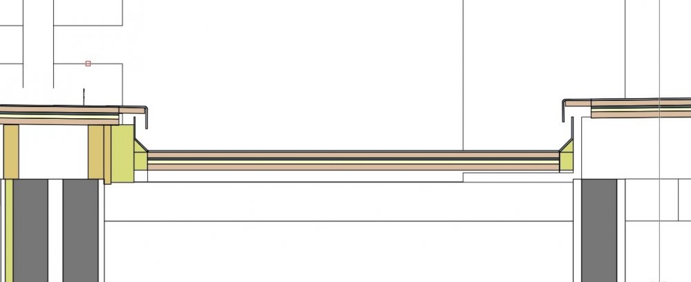
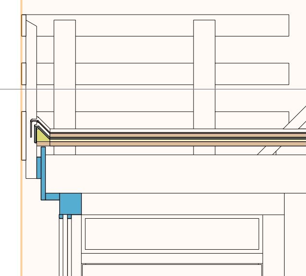
Here is a real world "as existing" roof I'm modelling at the moment. It's a series of flat roofs that have been added onto over time so there are several different parts, a variety of different flashings and multiple layers (eg fibreglass laid over previously existing felt). The roof face tool is pretty useful for getting the main flat areas right because it draws the multiple layers and I can tweak the falls until it's right. But all of the flashings, drip edges and so on have to be modelled from scratch. That's all doable, although it leaves me with some junctions between the roof face objects and flashings, where a material should be continuous, which I'll have to disguise somehow. Some might say this is an excessive amount of detail to model in 3d but I find it helpful as part of the process of extracting info from my survey and making sense of it in 3d. At the moment the sectional details I can extract from the model look like this (work in progress) It this stage in the process I give each material a colour fill so I can easily see what's going on everywhere. Later down the line I usually change the colour fills to hatches so as to make more conventional construction drawings. I often try to get as much of a 1:20 or 1:10 detail directly from the model, and minimise the amount I have to patch up with annotations. In this case, at least modelling the outermost layer of the roofing in 3d is necessary for me to get decent roof plans or elevations out. If I didn't model all those fibreglass flashings, it would look completely wrong and fail to convey quite a bit of important info. I'd be impressed if someone could build me a tool that let me model all of these different flashings parametrically. It would certainly be useful to be able to "attach" a custom set of extrusions along each edge of a roof face and have them follow that edge if the fall is altered (if I change the fall on any of these roof elements I'll have to manually rotate or adjust each edge flashing).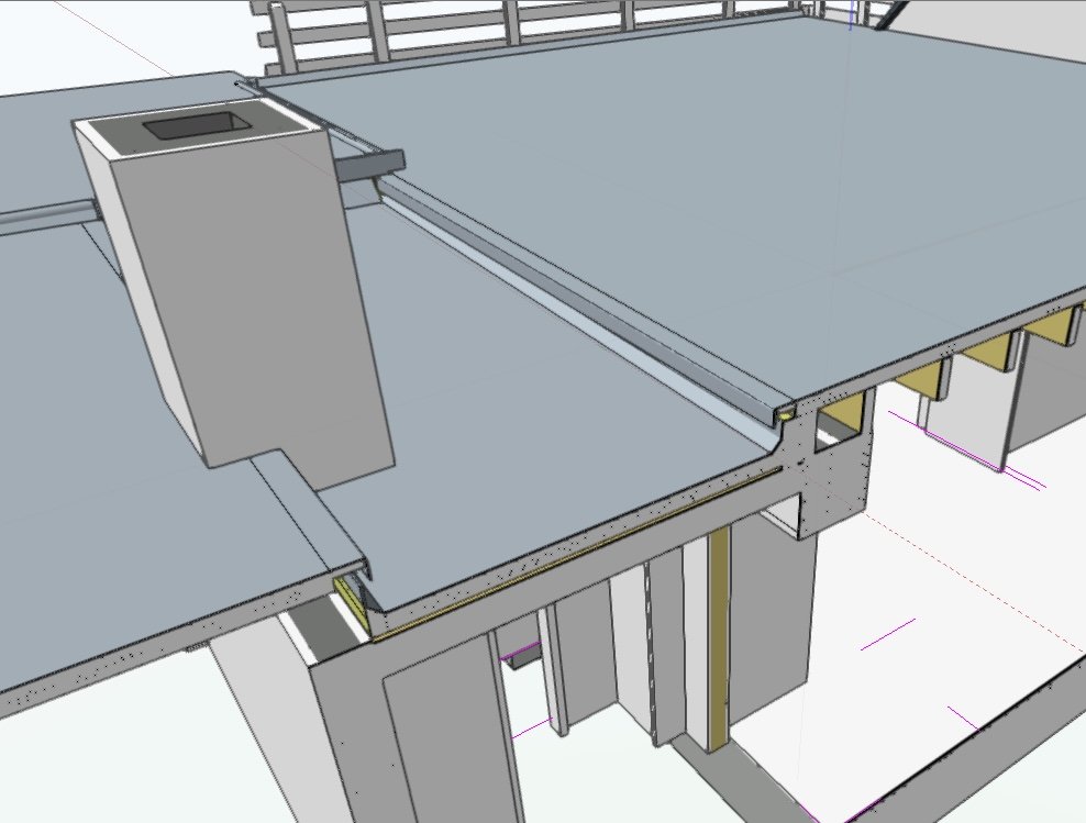
-
Stories & levels - things that don't work as expected
line-weight replied to line-weight's question in Troubleshooting
Indeed! -
Stories & levels - things that don't work as expected
line-weight replied to line-weight's question in Troubleshooting
Thanks for the clarification - I think I understand it - although I still think the terminology is confusing. It seems you are saying that "level types that are available by default when creating stories" is something different from "default story levels" because a level type has no elevation attached, but a default story level does. However - my point remains that it appears to be impossible to follow the instructions given in the documentation. Once I have opened the "level types" dialogue as instructed, I do not see how to "specify the level types that are available by default when creating stories". PS. I would find the following terminology less confusing, although there are probably better solutions: "Level type" - as it currently is "Level" - a level that has an elevation "Level presets" - a level with a preset elevation I think calling them "story levels" is unnecessary and adds confusion. I think that calling a level type "layerless" is also confusing, in fact the whole way the dialogues try and create a layer along with a level and/or a story is massively confusing. I think this has been covered before though. As with so many things in VW, we have certain concepts like "styles" that we ought to only have to get our head around once, and then be able to apply it to various different tools and objects... but for example with levels, the "styles" concept isn't used at all whereas I think it could be, for example potentially "default story levels" should really be "styles" (I dunno, shouldn't be my job to give myself a headache trying to work this out) -
Stories & levels - things that don't work as expected
line-weight replied to line-weight's question in Troubleshooting
Ok - but if you give people the opportunity to make a new level (whether or not it's a new level type) from the 'edit story' dialogue, then doesn't this imply that they are wanting to use this new level in the story they are editing? Because I don't see any reason that you would create a new level that you didn't want to use. Therefore, I would expect it to be added to the levels used in that story, meaning it should automatically appear with a tick against it, as a result of this action. -
Wall object: bounding incorrectly to story levels (VW2021 SP4)
line-weight replied to line-weight's question in Troubleshooting
As per other thread - I don't see why the insertion options should be relevant to an already-existing wall, which I've actively chosen to bound to something different. -
"Delete wall peaks" loses and changes top and bottom bound associations.
line-weight replied to line-weight's question in Troubleshooting
That doesn't make any sense to me because I'm not inserting a new wall - I'm editing an existing one. Why would anyone want a wall to revert to a default option during a "delete wall peaks" operation? -
Attached file contains one wall object. - select wall object, note which levels it's bound to in the OIP - run command "delete wall peaks" from the AEC menu - note that the wall is now bound top and bottom to completely different levels. The more I experiment with "levels" and bounding walls to them, the more unreliable they seem to be. They seem to have the ability to seriously mess up a drawing. peakbug.vwx
-
Wall object: bounding incorrectly to story levels (VW2021 SP4)
line-weight posted a question in Troubleshooting
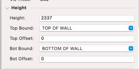
See attached file. It contains a wall object, which is responding incorrectly to the top bound (it is bound to a storey level). The height of the wall does not match its height given in the OIP. Setting its height to zero in the OIP creates a wall with the correct height in the model. If I "cut" and then "paste in place", then it reappears and its height is correctly bound to the levels. This problem appeared after I made some adjustments to story levels in the file that I extracted this from. That included renaming some level types and I don't know if it's related. I'm now looking at having to go through the entire file, cutting and repasting each problem wall object, which means I'll have to rejoin them all too. I wonder if this is connected to the problem I identified here. wallbug.vwx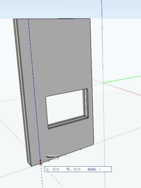
-
Stories & levels - things that don't work as expected
line-weight posted a question in Troubleshooting
It's been covered previously that the dialogues and mode of operation for stories & levels are very confusing but here are two things I've found as I continue to struggle to use them: 1) Newly created "level types" disappear - To make a new level, go to organisation palette, stories tab. Highlight relevant storey, click “edit” - Brings up “edit storey” dialogue, click “new level” - Brings up "new storey level" dialogue - Invites choice of an existing “level type” via dropdown, can use an existing type, or choose “new level type” within dropdown - Choose "new level type" and give it a name and elevation - exit "new storey level" dialogue - the new level appears in the list within the "edit storey" dialogue, but without a tick next to it - if you now exit the "edit story" dialogue, without putting a tick against the level in that list, the newly created level type simply disappears. - is this intended behaviour? Doesn't seem logical to me. Either, automatically tick it, or don't, but keep it available as a "level type" that I can go back and make active in whatever story. 2) Not possible to make an existing level type a "default story level" - maybe I'm missing something but following the instructions here doesn't work: https://app-help.vectorworks.net/2021/eng/index.htm#t=VW2021_Guide%2FStructure%2FDefault_story_levels.htm%23CSH_15 specifically, I don't see how to do the step that I have highlighted in blue here: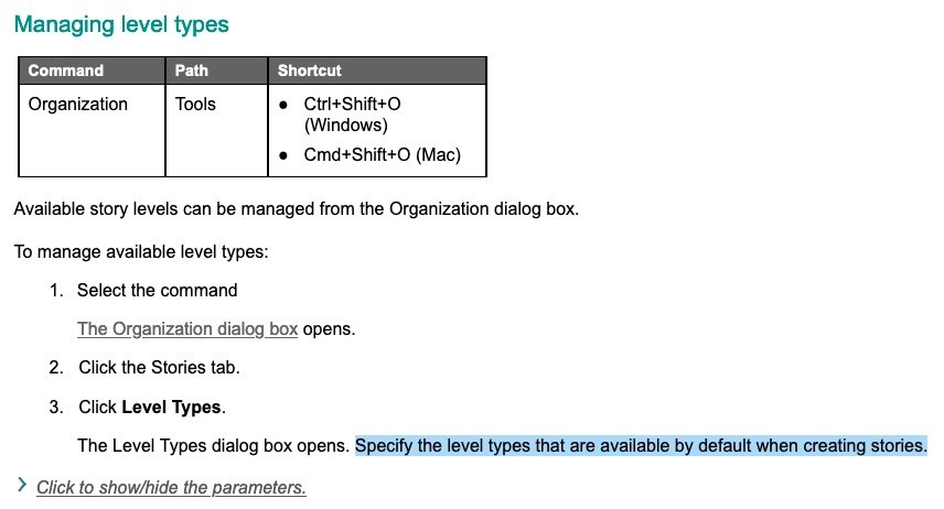
-
"functional" performance problems - multiple view panes
line-weight replied to matteoluigi's question in Troubleshooting
I think there are various bugs to do with multiple view panes. At least, when I use a 'floating view pane' I experience problems. For example, very glitchy behaviour in sheet layer viewports in the main pane, with a mess of geometry flickering in and out of view when zooming. Snaps don't behave properly in the floating view pane. Jerky 3d navigation.


