line-weight
-
Posts
3,757 -
Joined
-
Last visited
Content Type
Profiles
Forums
Events
Articles
Marionette
Store
Everything posted by line-weight
-

VW24 - Window shows wrong exterior hinge markers
line-weight replied to bjoerka's topic in Architecture
How strange. The perfect way to direct rain straight into your house. -
VW 2023 - Window PIO Issue - Insertion Points / Offset in Wall Depth
line-weight replied to zoomer's question in Troubleshooting
I can see there are legitimate arguments for various options - nothing / grey square / window-like symbol. In the end, my point is really just about consistency. Whichever approach is decided upon, I think it should be applied to all of the illustrative diagrams in that interface. So if the decision is that a grey rectangle is the best compromise ... I would use it in those two other diagrams too. This may seem like a small thing to be fussing about, but I think that it would reduce the mental burden on users trying to work out what's going on. Once you've figured out what the dotted grey rectangle represents in one place, your work is already done when you meet it elsewhere. Thanks anyway for the explanations.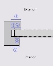
-
VW 2023 - Window PIO Issue - Insertion Points / Offset in Wall Depth
line-weight replied to zoomer's question in Troubleshooting
I assume these are automatically generated when you do it within a window object. I wonder what happens to wall closures if you make a custom symbol of your own, and define your own wall hole and make it non perpendicular to the wall. I had better get on with some real work now though. -
VW 2023 - Window PIO Issue - Insertion Points / Offset in Wall Depth
line-weight replied to zoomer's question in Troubleshooting
I think it would be ok if it was just a basic window representation regardless of whether you're inserting a window, door or custom symbol. That's what you get (as far as I can see) in the two other locations within the closure dialogue, regardless of what you're inserting: I do get that it is difficult to make a decision on what's the least confusing approach though. The way I see it, once people are using custom symbols, they are probably deep enough into things that they can easily understand that the representation is just diagrammatic. My aim would be to make things as legible as possible for someone meeting the interface for the first time, and at that point they are likely just to be wanting to insert a standard window or door. Anyway, yes I do agree with you that the green text in the Help page is a bit confusing/unclear.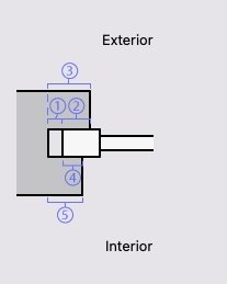

-
VW 2023 - Window PIO Issue - Insertion Points / Offset in Wall Depth
line-weight replied to zoomer's question in Troubleshooting
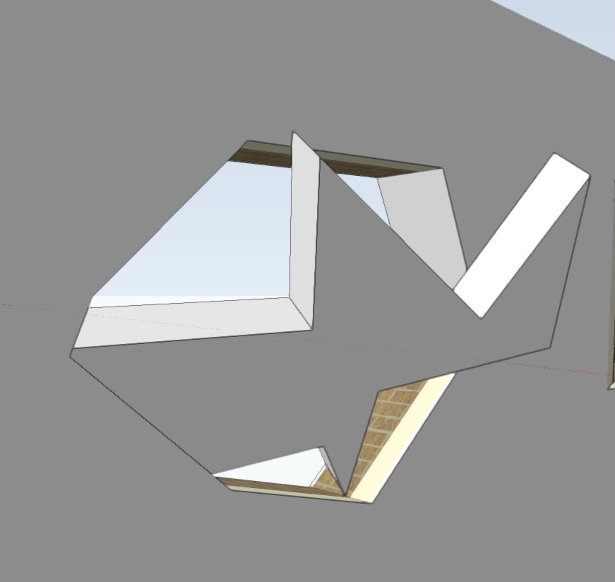
Veering slightly off topic... I did a little test to see what happens when you use a non rectilinear symbol as a "window" (that is, using the "use symbol geometry" within a standard VW window object). It looks like it cuts a hole perpendicularly through the wall based on the object's outermost extents, and then it decides the closure arrangement for each side of the resulting polygon based on how close it is to being vertical or horizontal. In this case I have it set so that components "wrap" at left and right sides but not top and bottom.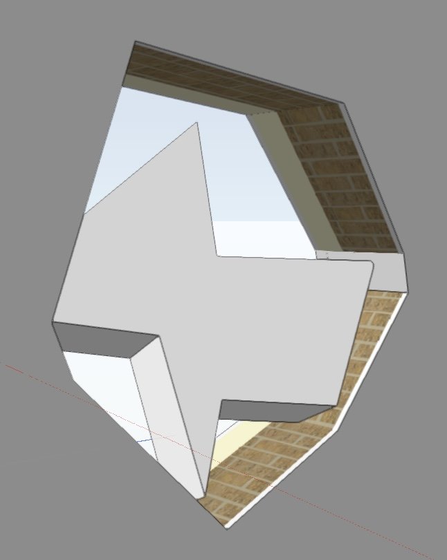
-
VW 2023 - Window PIO Issue - Insertion Points / Offset in Wall Depth
line-weight replied to zoomer's question in Troubleshooting
I'm assuming that the preview creates a basic cuboid type object, because there are in the end only 6 planes (exterior/interior, 4 sides) that can interact differently with the wall, and its those 6 interactions that the preview tries to show? And the complexity of the insert object itself doesn't change any of that, or does it? Reason I ask is, would it not be possible to draw a basic 2d shape, that resembled a window, in place of the grey square, in what is shown to the user. -
VW 2023 - Window PIO Issue - Insertion Points / Offset in Wall Depth
line-weight replied to zoomer's question in Troubleshooting
No - I just get that grey rectangular zone, and have to put the thickness/insert origin in myself.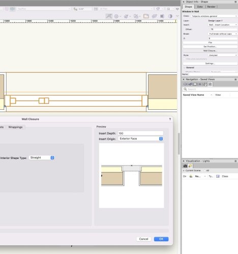
-
Quickest way to find an intersection of solids surfaces?
line-weight replied to line-weight's topic in General Discussion
Yes, I suppose that should have worked for me, at least for two of the extrudes. Unfortunately I often find these "smart edges" and so on rather janky. VW doesn't reliably find them for me. I think it gets worse, the more complex my model gets. It is often seeing ghost objects and so on. I wonder if this is another thing that is worse in perspective (which I like to work in) than it is in orthogonal like in your recording above. -
Quickest way to find an intersection of solids surfaces?
line-weight replied to line-weight's topic in General Discussion
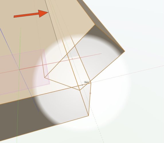
Aha! Thanks. Have never used this tool. I will now. -
VW 2023 - Window PIO Issue - Insertion Points / Offset in Wall Depth
line-weight replied to zoomer's question in Troubleshooting
By the way I just had a look in VW help to see what it says about this section. I don't quite understand what the green text means. In my example I have opened the dialogue for an "insert" (a standard window). So is a representation of that particular insert supposed to display?
-
VW 2023 - Window PIO Issue - Insertion Points / Offset in Wall Depth
line-weight replied to zoomer's question in Troubleshooting
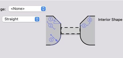
Yes, I am sure there are all sorts of horrible complexities that I am unaware of. Where terminology can't be made clearer there is always the opportunity for visual hints. When I first met this interface there were two things that confused me. One was the fact that the preview requires some manual input of data and that changing settings here doesn't change anything in the drawing. But there's not much to signal that to the user. That's not something that really occurs elsewhere in VW (that I can think of) so I think there could be something that makes it more immediately clear what is happening. Some cursor prompts do appear in small text when you hover over the settings, but could that text not be written immediately above the input fields? The other thing is the "grey zone" that appears in the preview image. This represents the region where the "insert" will sit, but I spent some time thinking it represented a depth zone between the outside face of the wall, and the outside face of the inserted object. That's partly because "insert depth" (where I'm invited to type a number) could be read to mean the depth of an inserted object or the depth at which an object is inserted. In fact I have to confess it's quite hard to think of an alternative name for this field that is unambiguous. Hence I'd wonder if better graphical hints could help. I appreciate that in some cases it won't be a window going in here but could be some kind of custom symbol. So perhaps that's why it's just shown as a "grey zone" rather than something that looks like a window. However - in the diagram immediately adjacent to it, in the "profile offsets" panel, someone has made the decision that this diagram will show a simplified typical window shape. So why the inconsistency between these two illustrations, that appear next to each other in the same interface? If the "preview" image showed a simplified window-type shape, just like the other one does, I think that would go a long way towards making it more immediately apparent what's being shown.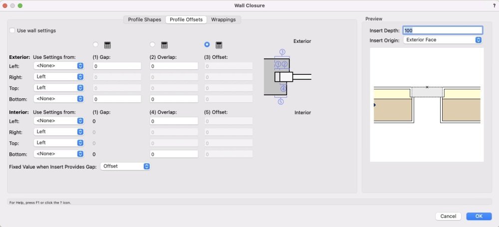
-
VW 2023 - Window PIO Issue - Insertion Points / Offset in Wall Depth
line-weight replied to zoomer's question in Troubleshooting
Ok - thanks for the reply. I guess I will revisit this whenever I get around to migrating to VW2024, and understand the changes that have been made to how closures are defined. -
Quickest way to find an intersection of solids surfaces?
line-weight replied to line-weight's topic in General Discussion
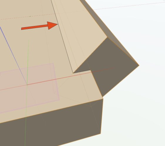
Here is one example of the kind of convoluted operations I end up doing, to achieve something seemingly straightforward. Hopefully the intended end result is obvious from the recording. Screen Recording 2023-11-07 at 14.25.13.mov -
Quite often I am trying to find the line that sits where the faces of two solids intersect. As indicated by my red arrow. (The solids have not been added together - they are two separate solids whose volumes overlap) If I want to find this line exactly (without doing a solid addition/subtraction which will make it become an edge) all my current methods are rather convoluted involving drawing intersecting 2d lines on working planes. Is there some straightforward way of finding that line (or points on it) that I am missing?
-
First, you have to explain what you mean when you say a layer "shows" no classes. Otherwise your question doesn't make any sense. A design layer in itself doesn't have any control over whether classes are "shown". You say design layer 1 "shows" the baseplan. Presumably that means that the objects that make up the baseplan are located on that design layer. And those objects are all in a class, because every object has to be in a class. So I don't understand what you mean by "shows no classes". Something to check is that you are not getting confused between sheet layers and design layers. A sheet layer can contain a viewport, and then that viewport can control which design layers and/or classes it shows.
-
Cutting shafts through multiple Slab objects?
line-weight replied to TaylorK's question in Troubleshooting
I don't think this is possible. In a similar vein, it would be very useful to be able to cut holes through multiple wall or (especially) roof face objects, using just one object- 1 reply
-
- 1
-

-
Is there any good reason not to change that design, to make everyone's life a bit easier?
-
VW 2023 - Window PIO Issue - Insertion Points / Offset in Wall Depth
line-weight replied to zoomer's question in Troubleshooting
I'm largely just quibbling about confusing/inconsistent terminology that is one of my bugbears, throughout the VW UI. But yes, in the preview (as far as I can make out) Insert Depth = overall depth of the window object (or other symbol) you are inserting, and you have to set this yourself Insert Origin = where, within the window object, not within the wall the insertion point for that window is, and you have to set this yourself As far as the insert location (the location within the thickness of the wall, where the window gets inserted) is concerned, settings you make within the wall closures dialogue are reflected in the preview but may or may not reflect reality, and settings you make in the plug-in object options dialogue aren't reflected in the preview and you can't manually add them to the preview yourself. -
VW 2023 - Window PIO Issue - Insertion Points / Offset in Wall Depth
line-weight replied to zoomer's question in Troubleshooting
Then of course on top of this, there is the choice of where the window's "insertion point" is, relative to the window geometry. (That'll be the "insertion point" that gets called the "insert origin" in the preview image, just to add a little more uncertainty about whether it's referring to the same thing. And of course the "insertion point"/"insert origin" gets placed at the "insert location", not the "insertion location".) -
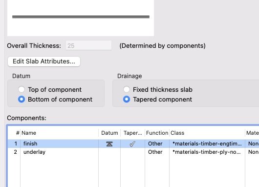
The thing is that a component has thickness, so it should really be represented with a rectangle not a line. In conventional architectural drawings, you'd not generally use that symbol to point at just a line, you'd use it to point at the top or bottom of a slab, which is a thing with thickness, and having the arrow point up or down helps with legibility (quickly understand that something refers to a ceiling level, say). If a symbol like that is use on a line, like for a reference datum level, then it doesn't technically matter whether it's pointing up or down... because a line has no thickness.
-
VW 2023 - Window PIO Issue - Insertion Points / Offset in Wall Depth
line-weight replied to zoomer's question in Troubleshooting
It's actually even slightly more confusing than that because while the insert location is either/or, the offset can be cumulative (if you choose the insert location to be determined by wall closure settings then the offset in the PIO options is added to the offset in the wall closure settings). And the cumulative effect is not reflected in the semi-fake preview. -
It appears in slabs too, for the reference datum, but with a confirmatory radio button above which is either "top of component" or bottom.
-
That's weird. Where exactly is that screenshot from, the options for what? I'd assumed this was because that symbol started out as something used to indicate whether a reference point was on the underside or top face of an object, perhaps before multi component objects were a thing.
-
VW 2023 - Window PIO Issue - Insertion Points / Offset in Wall Depth
line-weight replied to zoomer's question in Troubleshooting
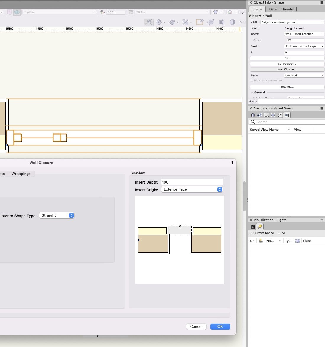
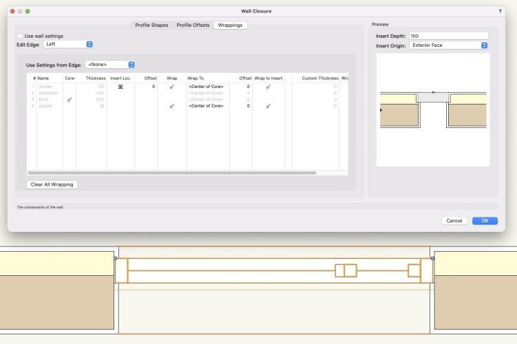
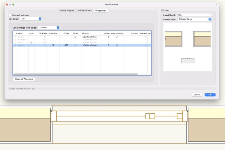
Having had a brief look in VW2024, this is still the same there - is that right? This is really a major source of confusion because if I decide that the wall closure settings for a certain window are going to be determined by that window, not by the wall's "suggestions", and untick the "use wall settings" box in the window's OIP, if I start interacting with settings offered to me for that window instance it seems reasonable to assume that any adjustments I make in those settings will apply to that window instance. Let's say I have also gone into the "plug-in object options" for that individual window instance, and chosen an insert location for it, and said that this will be determined by the "wall - insert location" plus an offset. This places the window into my wall like this - which is what I want (the offset is from the interface of the brown/yellow components) But if I now go to the wall closure options for that window instance (which are being controlled by the window, not the wall) I get presented with this: There are three issues: 1. It lets me edit the "insert location" and "offset" columns in those wrapping settings, and it adjusts the preview accordingly: And yet, these changes to the settings have no effect whatsoever on the actual window. It's not just that it lets me edit them (when they should be greyed out, because I've chosen to determine the insert location by other means) but it even shows them taking effect in preview, just like the wrapping settings (correctly) show in preview. So it gives me this twofold feedback that firstly I can edit, and secondly here are the results of that edit. And yet it's all in fact entirely futile. 2. The preview does not automatically show the (real and effective) window offset that I've already applied in the other settings. This is yet further reassurance that it's the offset I'm editing in the adjacent table that's the effective one. 3. Ok, so maybe there is some technical reason that the real offset can not be shown in that preview. Anyone who's already been fiddling with this feature will probably have realised that this is a kind of semi-faked preview because you have to manually enter the depth of your "insert" and its origin location, but it doesn't let me manually enter its offset within the opening, so it's not actually possible for me to generate a representative preview even manually. (I think the fact that this preview is not a true automatic one needs to be signposted more clearly in general in the interface by the way, this caused me confusion in itself for some time. Additionally the terminology "insert depth" and "insert origin" is inconsistent and misleading but I haven't the energy to type out why.) Ok, so that's my moan about this bit of the interface, which frankly I think is awful. However so as not just to be negative about everything, I think this ability to do wall closures, once you work it out, is a really big step forward and well done for getting it implemented. I can only imagine how complex it all is, behind the scenes.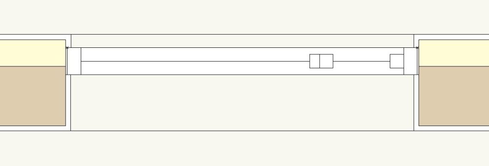
-
VW 2023 - Window PIO Issue - Insertion Points / Offset in Wall Depth
line-weight replied to zoomer's question in Troubleshooting
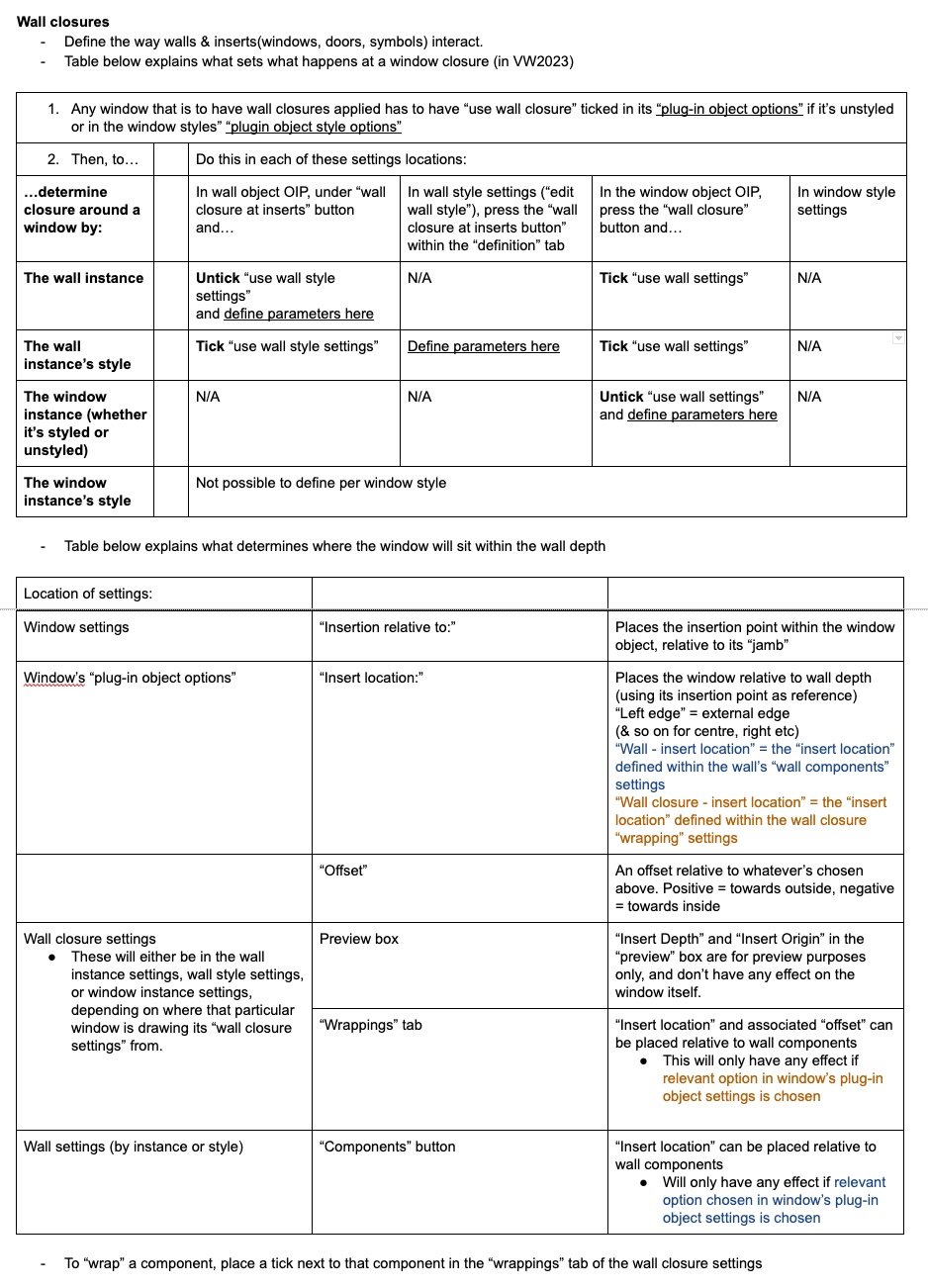
Today is the day I chose to start grappling with wall closures, which I've so far not started using. Taken me at least 4 hours to get to a point of understanding basically what determines what happens where. I came up against nearly all of the exact same issues that are described in this thread by @Tom W., @zoomer and others. Hence ending up finding more useful info in this thread than in the official help. I presume everyone goes through some version of this. I often end up doing a "write-your-own documentation" exercise when I'm figuring out a new VW feauture, partly because it helps me get my head around it but also because there are often gaps in the official documentation. I've posted below what I have written in case it's of use to anyone else. There may well be errors/incompleteness in there. This is for VW2023; I'm aware some things have changed in VW2024.