line-weight
-
Posts
3,755 -
Joined
-
Last visited
Content Type
Profiles
Forums
Events
Articles
Marionette
Store
Everything posted by line-weight
-
 There's a column in the table that I made as part of this exercise that's about whether the class can be set...
 -
I think the numbering should start at -5 and go up to +5 so that update zero is the one that occurs when it's safe for most people to consider starting to use it for real.
-
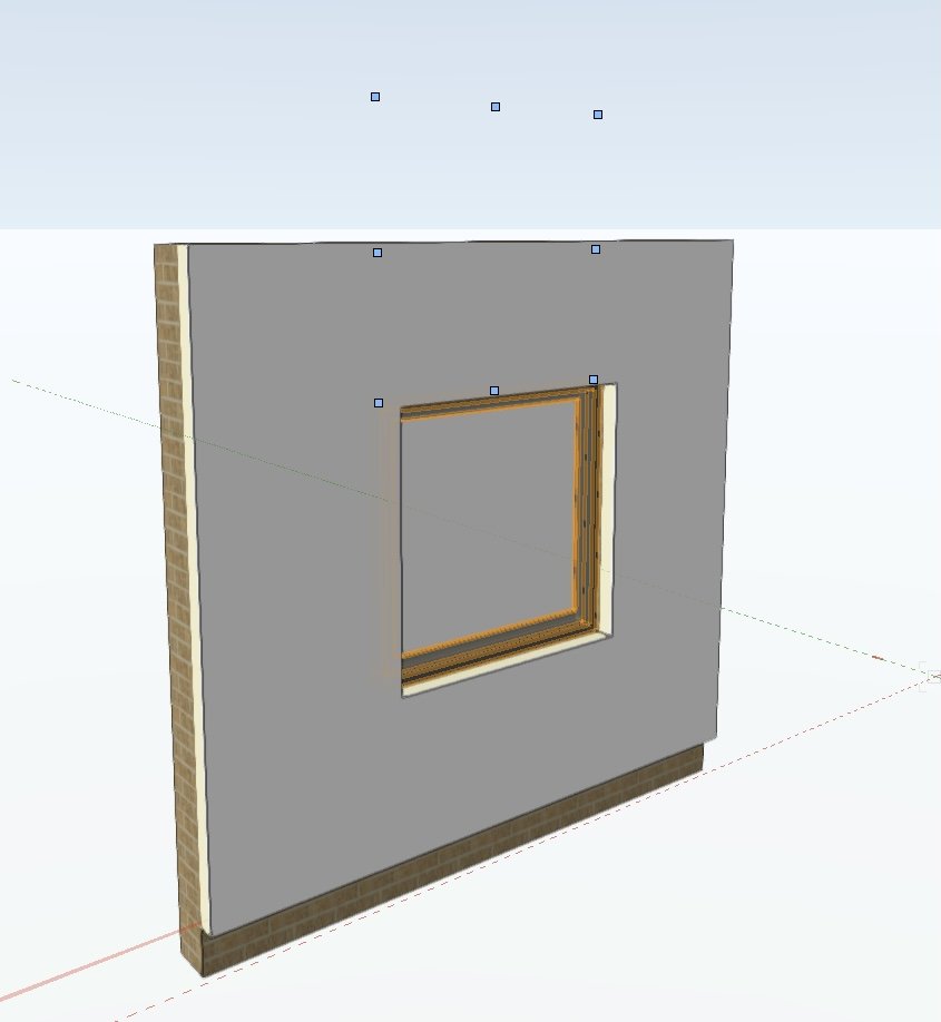
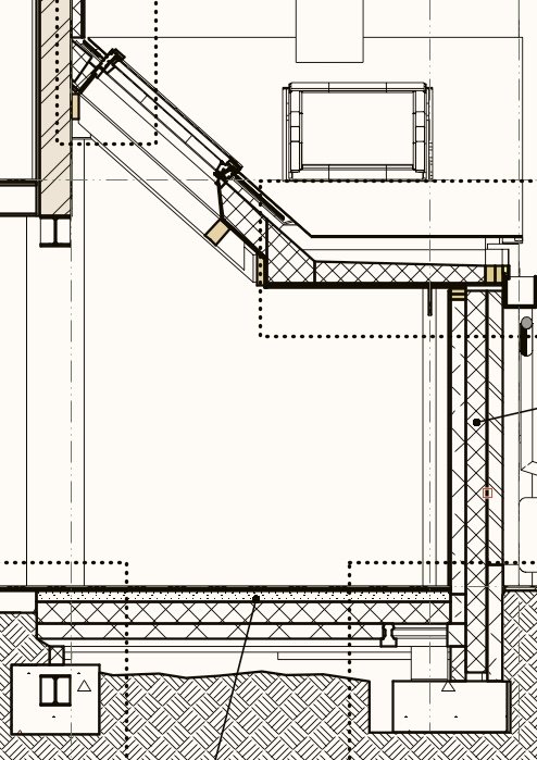
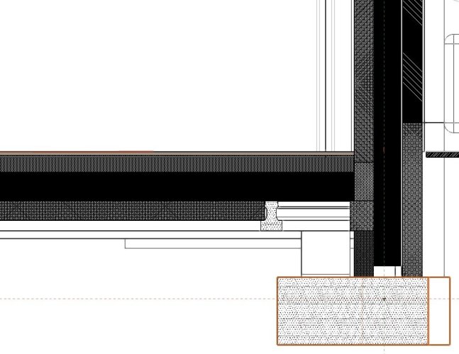
Latest experiments in Velfac window-making: I want to start using wall closures and this rules out the bodge solution above (putting separate window objects into a dummy wall). Also, I want to start using "show 2d components" in my horizontal sections. Even if I can manage to build something approximating a Velfac frame, the fact that VW is unable to draw a window properly in 2d plan component view means that I can't use it in a horizontal section with "show 2d components" switched on. This afternoon I tried with WinDoor. It fails on multiple slightly different counts. It can't have different inner/outer materials for the frames. You can make a very simple representation of a multiple-section Velfac window (basically just a single 149x50 rectangle for each "sash" with a very thing "frame" or mullions inbetween) but it can't draw glass with any thickness (ridiculous at larger scales if you've got triple glazing) nor can you control where the glass sits within the sash, and it draws the glass sliding right through the sash. It would just about do for 1:100 and maybe 1:50 but nothing larger. Additionally if you make the sash overlap the frame, it can't draw this properly - it fails to occlude the frame where the sash overlaps it so you get lines that shouldn't be there. So, I think the only solution is really to model each window from scratch, make into a symbol and insert into walls & take advantage of wall closures. That's the only way I can get this software to draw me a window, at a scale larger than about 1:100 and have it look ok on a floorplan, that is match the standards I'd expect if I was drafting it in 2d. It's a very poor show.
-
Windoor object handles in the wrong place
line-weight replied to line-weight's question in Troubleshooting
Well - re-installing WinDoor seems to have fixed it. Thanks @Matt Panzer. -
Windoor object handles in the wrong place
line-weight replied to line-weight's question in Troubleshooting
Hm. That screenshot is taken in 2023 SP7. I think that's after a restart of VW (as a result of a crash caused by trying to do something to a Windoor object). Will double check. How do I update Windoor? -
What's going on here with the selection handles? VW file attached (VW2023) windoortest.vwx
-
2008: 2015: 2020:
-
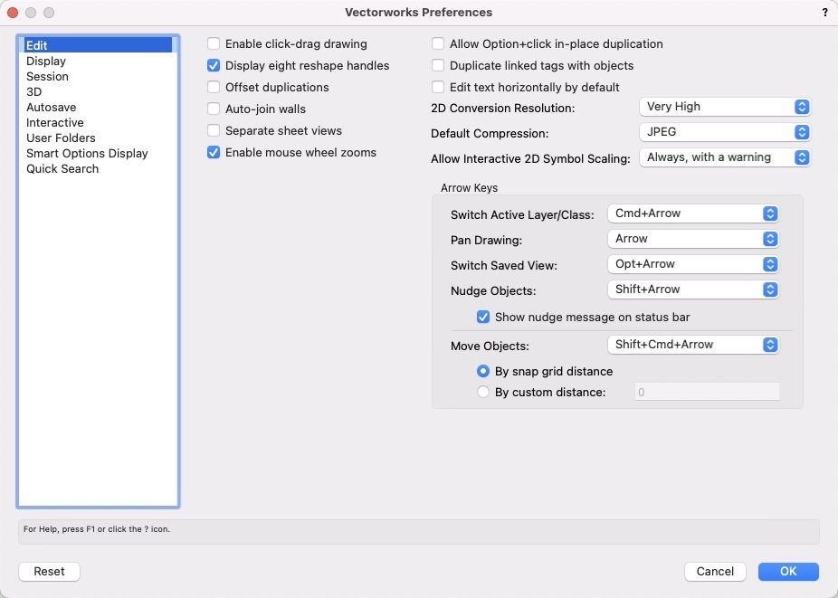
Have you checked that "default compression" is the same? I've found that changing between JPG & PNG can have a significant effect on file size.
-
Vectorworks exporting huge PDFs has been a problem for ages and it's very frustrating that it never gets addressed, along with the fact that colours get altered in certain forms of export as well. PDF is now the main way that information is issued and it really shouldn't be like this. Do you get a different result if you use "publish" instead of "export to PDF"?
-
This works! I have to double click each data tag to persuade it to update itself though. Can I somehow use an "IF" type formula in there? So, if a field name in the record format = X then write Y in the data tag?
-
Ok, thanks. Had to remind myself of exactly what Record Formats are and how they work. I think I get it now. I don't think I can use this to do quite what I want. My list in that pop-up could be G.01 living room G.02 kitchen G.03 bathroom etc and then if G.03 became a bedroom, I could change that in the record format pop-up (=drop-down?) list and then it wouldn't automatically repopulate everywhere but I could go around and update by resetting as you say. But it wouldn't let me put "G.03" and "bathroom" in different fields in the data tag and have them both updatable in conjunction with each other.
-
One thing it demonstrates is that it's easier to reposition a piece of furniture in a 3d view in a rendering application, than it is in VW. Hopefully soon we will be able to use the 3d dragger thing to do that. But yes of course that looks a much nicer environment in which to render things than using RW. Having moved the chair, how easy is it to replicate that repositioning back in the VW source file?
-
If I were doing mechanical engineering type drawings I might well have eg. "front" and "side" view viewports, rendered in hidden line or dashed hidden line, right? I'd have thought that in that context, it would be very surprising if I could not dimension a circular feature, and this was intended behaviour.
-
I think I still don't quite understand this. There is a data tag, and attached to this is a record, that has all of the info that you want for all data tags in the file? And then other data tags refer back to the record attached to this "master" data tag?
-
I don't think they are really "too limited" - I think you were trying to use a section viewport when what you wanted wasn't really a section. Section viewports are critical for architectural documentation. 99% of all orthogonal viewports I create for architectural projects are section viewports. They are what you use to show the detail of internal buildups of walls, roofs and so on. They are also what you use to explain the relative levels of the interior of a building and the relationship to adjacent buildings, site levels etc. In practice they are also what you use for external elevations (or at least I do) because buildings aren't free floating objects - they are always embedded in a context. So a building elevation is really a section through the landscape parallel to the face of the building you are looking at.
-
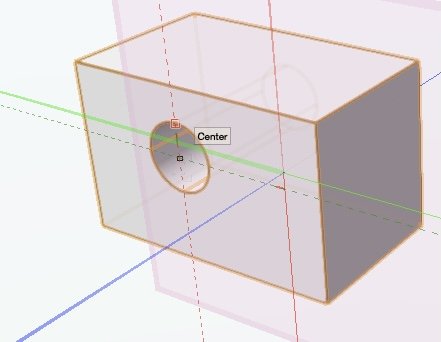
Certainly you can snap to the centre of a subtracted circular hole in a design layer.
-
yes you can certainly do it with class over-rides. And this is what I do in some cases. However it becomes very tedious keeping it up to date when you have a lot of viewports, and it doesn't let you toggle back and forth between a colour/hatched version. Viewport styles would appear to make this much easier though. (I've not yet started using 2024 so haven't actually tried it yet)
-
Agreed. It's certainly satisfying to get these things working (and once you do, you can recoup the benefits on future projects too). However, for myself I am conscious that it can become a procrastination device to avoid getting on with the proper work!
-
Thanks. It sounds like I can probably have a better setup, once I can transition things to VW2024 and start using materials. So it's not really worth trying to change my current system for the projects that currently live in VW2023.
-
When I said "refer back to a worksheet" perhaps what I mean is a record? But yes just a dumb table of some kind where I enter the info manually - and where I could change, say, a room code number and have it automatically update across the drawings. I suppose I should try using spaces and also returning data directly from window/door objects. I feel like I quite often read comments about people having difficulty getting data tags to work properly so am not sure if that additional layer of faff is worth it for me, on projects that don't contain vast numbers of these objects. Plus a large proportion of my doors & windows often end up as custom built objects where it would be extra work to attach that data to them properly.
-
So I'd just make a data vis that says anything that has "brick" material assigned to it, instead of filling it with "brick hatch" in section, fill it with solid brown, and I'd set up one of those for each material?
-
Yes, I can see that things will be a bit easier once I can start using viewport styles - at least as far as the viewports themselves are concerned. How would it happen using materials? Can each material have an fill alternative and hatch alternative set for it? And then the data vis chooses which is shown, across all materials?
-
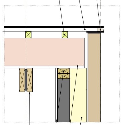
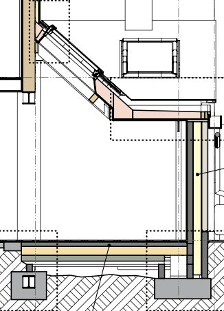
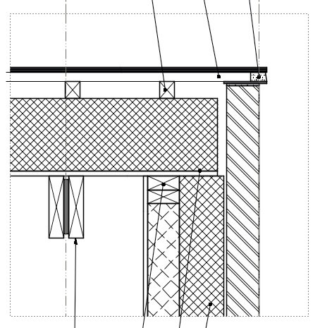
I think the answer here is "no" but want to make sure. Here's my basic issue. I tend to give all objects & components what I call a "material class" and this is what determines what they look like in section. At an early stage of a project, for most of these "material classes" I use a solid fill colour. This is so that when I am working on section details it's dead clear what is what, material-wise. So a section at this stage of the project will look something like this: However, at some point (and it's never easy to decide exactly when to do it) I'll flip all the drawings over to a style where everything sectioned has a hatch instead of coloured fill. So those two same extracts will look more like this: This switchover generally happens when I'm getting closer to the point of formally issuing construction or pricing drawings. The reason I tend to change away from the block-colour version is mostly a long standing principle that black & white linework is more likely to survive things like photocopying or bad quality printers. This is perhaps become less and less meaningful as things are increasingly viewed on screen rather than paper but that's a different discussion. Anyway... the point is, once I have made this transition to hatched versions, the drawings become less easy to work on, especially when I use the "Section In-Place" option to view design layers directly from section viewports. Because of the lack of control over hatch scale I end up looking at this kind of ugliness: in addition to this, my current process of starting out with solid colour fill and then changing to hatches is not very efficient, because of all the adjustments I have to make to multiple classes at the switchover point. Really, it would be nice to be able to switch between the two modes at any time (and switch any viewport back and forth with minimal effort). And I started wondering if I could do this using data vis. But as far as I see I can't. (All of this to some extent takes advantage of a quirk of how VW fill attributes work ... something can have a solid colour, and you can then choose a hatch instead, and if you then go back to the "solid" option, it will remember this, but not vice versa.)
-
I think this is a bug & it needs to be picked up by any VW people reading this. I don't know if it's related to what's discussed here: https://forum.vectorworks.net/index.php?/topic/111074-radial-dimension-tool-not-working/
-
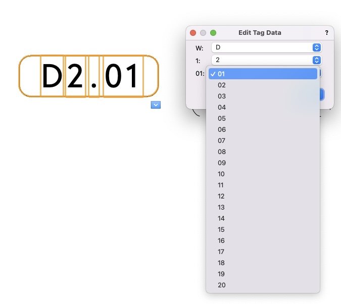
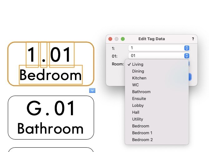
I've never really used data tags - but am starting to use them a little bit without actually associating them with any objects. Essentially I'm using them as a convenient way to place window/door/room labels. For example I have window labels set up like this - with simple drop-downs (that can be accessed just by double-clicking on the tag) to choose from: I also have a room number version Within a single project, if room 1.01 is a bedroom, then in every viewport where I want to place a room number tag and choose number 1.01, I want it also to say "bedroom". At the moment I just do that manually - I choose all three fields manually. Is there any simple way to set things up so that if I choose room number 1.01, it will automatically fill in the name field as "bedroom"? For example can the tag somehow refer back to a worksheet somewhere, where I make a table of room numbers & names? Or is this a stupid question and I should just be using it as intended, that is it should be associated with a space object on the design layer? (I've never bothered using spaces) Alternatively, is there a clever way of having a dropdown where one of the options include "1.01 Bedroom" and it will put the number & text into the two lines as per my screenshots above?