


line-weight
-
Posts
3,930 -
Joined
-
Last visited
Content Type
Profiles
Forums
Events
Articles
Marionette
Store
Everything posted by line-weight
-
Yeah you're right, that was the wrong example, it's my *objects classes that would be gaining the extra appendage. But some of them are similarly complex and are already hyphenated several times.
-
I have prefixes for classes like *objects- and *materials-. Typically a wall will be in something like *objects-walls-internal And its components in eg. *materials-masonry-brick-yellow_stock One of the reasons I'm reluctant to use classes to designate existing/demolished/new is that I would then end up with classes like *materials-masonry-brick-yellow_stock-new - but VW only recognises the first 3 hyphens (I think) and any more you use after that don't get collapsed in the class organisation dialogue so it becomes rather unwieldy. I can see that using brackets could be a clever way of giving oneself another level of hierarchy though...for objects [walls] [doors] but for materials {masonry-brick} {timber-rough-softwood} or something like that. But...then I wouldn't be able to collapse away all material or all object classes as I can now.
-
Are we talking about something different when we say container classes? When I say a container class I mean the wall object is in class "wall" and I then have to put it inside another container (for example a group) so I can then put that into a "demolished" class.
-
Does this involve some careful use of container classes? For example, say I have in my model: existing walls demolished walls new walls existing timber joists demolished timber joists new timber joists And I want to show: (A) the existing condition but I want to show walls only, and no timber joists (B) the proposed design but I want to show walls only, and no timber joists. Then it seems that for example any demolished walls have to go in a "walls" class and then into some container that can be classed "024000 Demolition" so that I can turn off "024000 Demolition" in to make sure they don't appear in (B) but I can turn on "024000 Demolition" so that they do appear in (A). I can't simply put the demolished walls and the demolished timber joists into "024000 Demolition" because then I can't show (A). To achieve that I have to do the container class thing - timber joist class object inside a Demolition class container, and so on. The alternative is to have a bunch of separate classes like Timber joists - demo Timber joists - exg Timber joists - new Walls - demo Walls - exg Walls - new And this is one of the main reasons I use layers instead - because the strategy above means potentially creating 3x as many classes as I'd otherwise need, and this seems much more complicated than having 2x as many layers as I'd otherwise need. In most of my models the number of layers is in single figures while the number of classes is at least in double figures.
-
I'd be interested to see a file set up to accomodate the following simple situation, using only one layer: Existing: a solid brick wall, with two windows in it. Plaster finish on the inside of the wall, which wraps into the window reveals. Proposed: one of the window openings is enlarged, the other reduced in size. The plaster finish has been removed, and replaced with insulated plasterboard. This also wraps into the window reveals.
-
I don't see the duplicate models as a problem, because you are not really trying to maintain and keep up-to-date two models. The "as existing" model, once you've built it, doesn't then change. By definition it doesn't change because it's frozen at a moment in time.
-
The official Vectorworks documentation on NURBS is very poor (it shouldn't need to be a process of trial and error) and this is only going to become more of a problem as more people move to modelling in 3d.
-
Yes I'm always interested to see how others set things up so if you have a sample, post it!
-
I use Layers. I have an "as existing" layer and a proposed layer. The "as existing" geometry largely stays as-is once I have draw things up from a survey. I find it useful to always have there in the background, to refer back to. In theory it can be done in classes, including with classes that are for objects that are existing, but to be demolished. In practice though, I find this just adds an extra level of complication to everything that doesn't actually provide much benefit. In particular wall objects can become very difficult to set up, where you have a run of wall that in the existing/proposed conditions is going to connect with different wall types at different places, may have various finishes added/subtracted, and openings removed or enlarged or added, and so on. You end up with a whole load of bits of walls that are then very troublesome to edit and this is more work than just copy-pasting the existing into the proposed layer and then making the modifications needed. My demolition drawings tend to be the "as existing" with demolished portions highlighted manually in annotations.
-
 My 16GB M1 Mini continues to work (with 3 monitors) just fine, for the most part!
 -
You might find it useful to look at this thread, also current:
-
Making a smooth transition (in 3d) between two NURBS curves?
line-weight replied to line-weight's topic in General Discussion
I'd really prefer the computer to do the legwork here, though. -
Making a smooth transition (in 3d) between two NURBS curves?
line-weight replied to line-weight's topic in General Discussion
But not a true circle, and sometimes this is important. -
Making a smooth transition (in 3d) between two NURBS curves?
line-weight replied to line-weight's topic in General Discussion
This doesn't create a NURBS curve that exactly follows the radius, unfortunately. Near enough for many purposes, for sure, but it's not geometrically accurate. By way of demonstration here's what you get using 4 interpolated points. The more points the better, but it never quite matches.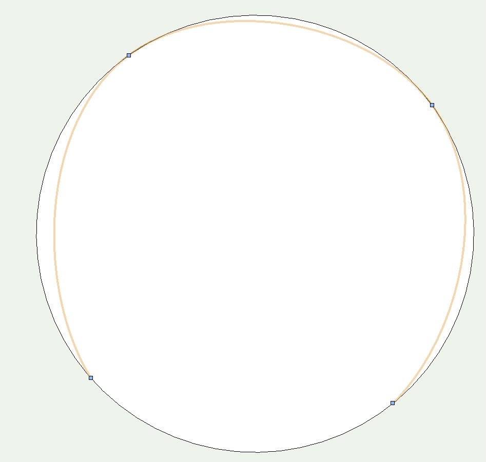
-
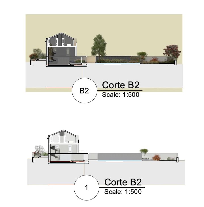
I've just had a quick look, and it appears that the problem exists when a Renderworks render is used for the viewport (top), but not when a "shaded" render is used (bottom). Does that match what you see?
-
Making a smooth transition (in 3d) between two NURBS curves?
line-weight replied to line-weight's topic in General Discussion
Because of the extra steps of extracting the curves and then creating the loft, it means going back a few stages if I want to change that radius. But I think yours is the cleanest method suggested so far, for creating the curves themselves. -
Making a smooth transition (in 3d) between two NURBS curves?
line-weight replied to line-weight's topic in General Discussion
... and second question, how did you achieve this? -
Making a smooth transition (in 3d) between two NURBS curves?
line-weight replied to line-weight's topic in General Discussion
How have you drawn the NURBS curves from scratch, to follow an exact radius in plan? -
Making a smooth transition (in 3d) between two NURBS curves?
line-weight replied to line-weight's topic in General Discussion
Yes, true, using the method you suggested. If I am being fussy, the problem using sweeps is that the cross-section of the handrail gets distorted on any steeply sloping sections. -
Making a smooth transition (in 3d) between two NURBS curves?
line-weight replied to line-weight's topic in General Discussion
I agree that this is a way of getting something like the desired result - and it's similar to what I did in the end. However, it still relies on tweaking those transition curves by eye, which is what I would like to be able to not have to do. When it's quite a small radius it is relatively easy to get away with but it becomes difficult when a larger radius transition is required - it becomes (to my eye) more obvious that it isn't a true constant radius transition. What I really want is something I don't think I can have, which is a parametrically controlled transition curve where I can easily type different radii into a box until I get what I want. It also all gets worse if you are trying to to an inner handrail, where the radius in *plan* can be much tighter and also when the transition from horizontal to quite steeply sloping is much more abrupt. Any little wobble gets massively magnified when you try and run an extrude along the path. And this is compounded with problems of excluding twist from the path. -
Making a smooth transition (in 3d) between two NURBS curves?
line-weight replied to line-weight's topic in General Discussion
Is this done with a loft? When I did a quick trial using my original curves, and a "one rail" loft, it produced a handrail with a twist in it. Are there extra steps I need to take? -
Making a smooth transition (in 3d) between two NURBS curves?
line-weight replied to line-weight's topic in General Discussion
I started this thread and then neglected it somewhat due to getting busy with other things. Thanks for the replies in the meantime. -
I was going by one of the sheet layers in the sample file, which has the RW viewport on it. However yes I see you're right, it renders out with wireframe type linework for the windowframes and I can't see how to get rid of that unless the pen is set to none.
-
The image in the OP is a renderworks render not shaded view. If the frames have no "fill" then I think that's what you'd expect to see in a RW render. Because it's using the "white model" preset render style, colours & textures are turned off and that's why the glass shows as opaque.
-
Just don't use it! The path animation tool is one of the most horrible things in Vectorworks. It simply is virtually impossible to create an animation without lurches and jerks. There are other threads on this.

