Bas Vellekoop
-
Posts
651 -
Joined
-
Last visited
Content Type
Profiles
Forums
Events
Articles
Marionette
Store
Everything posted by Bas Vellekoop
-

Combining nurbs surfaces
Bas Vellekoop replied to Samuel Derenboim's question in Wishlist - Feature and Content Requests
No there is not, sometimes it is possible to use the compose command or connect/combine tool from the basic palette. 99 out of 100 you will be getting a generic solid. But please feel free to make it a wishlist request, it is one of my long standing wishes -
@art V thanks for your help!
-
Multi-View Interface
Bas Vellekoop replied to PVA - Admin's topic in Wishes Granted / Issues Resolved
Really like it that this is discussed here so openly! Thanks @JimW! -
VW2016 Extremely slow after W10 Aniversary update
Bas Vellekoop replied to Mickey's topic in General Discussion
I think i have the same problem, my first thought it came of upgrading to VW 2017, but i have exactly the same issues as you. When i get behind my pc i will check if its the same in Vw 2016 -
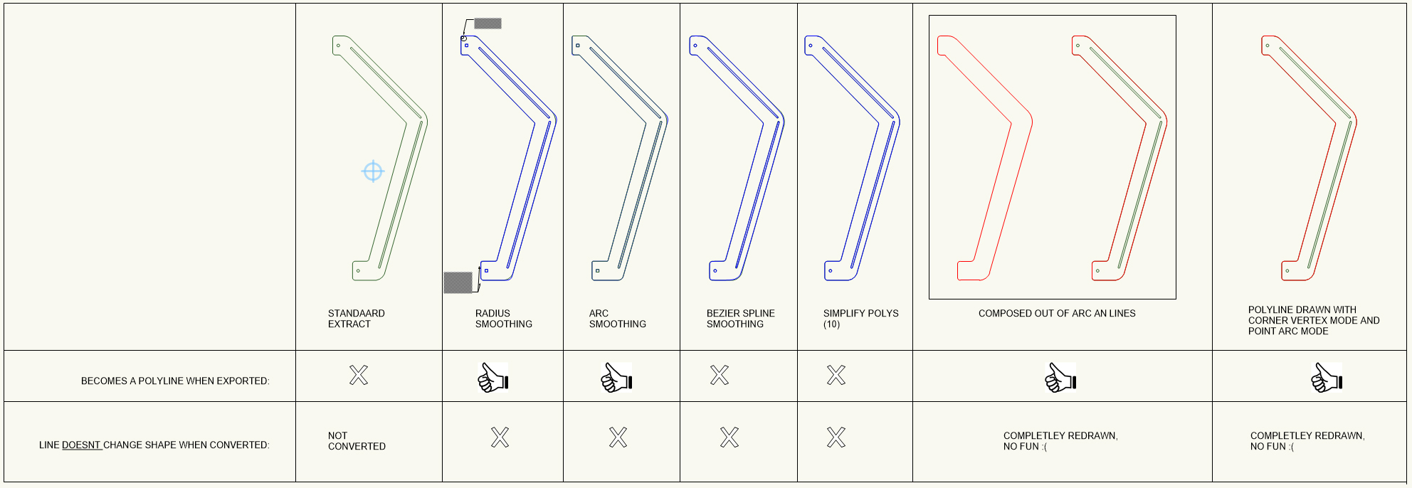
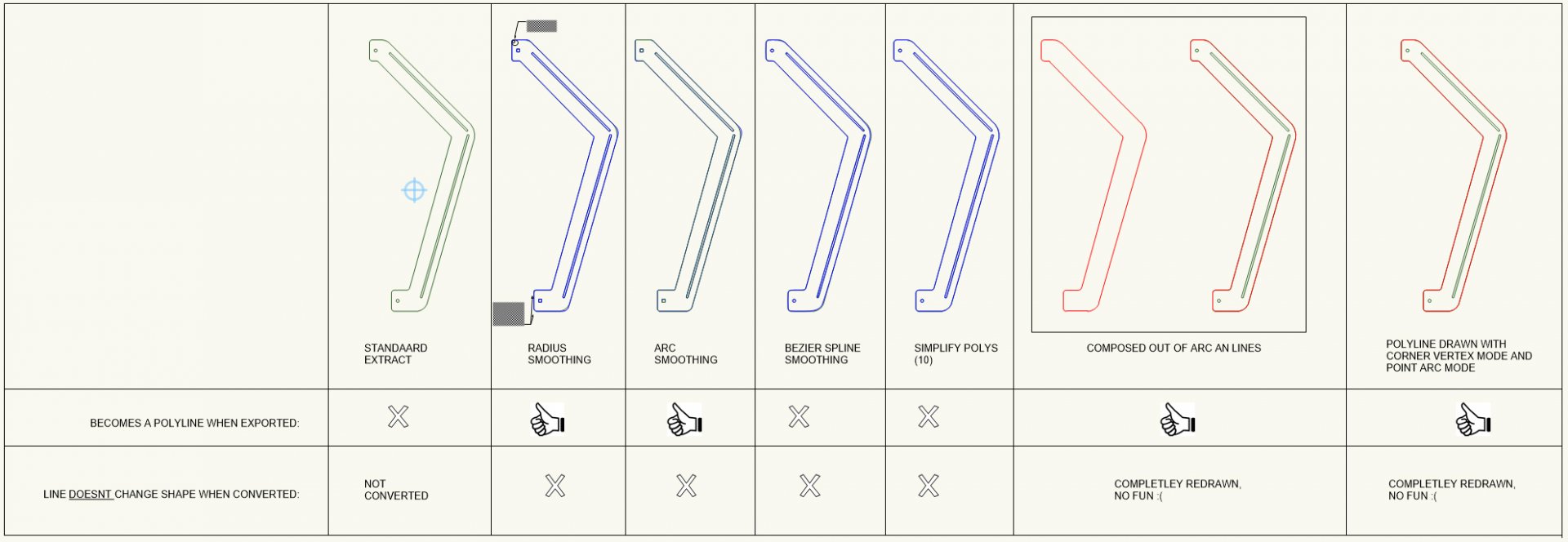
I did some further investigation for solutions, but not really happy with the outcome: First possibility: For a polyline to export and import as an polyline in Autocad the line should be build up out of: - separate arcs and lines that er composed in a polyline - a polyline that only uses the corner vertex mode and point arc mode But this means I have to completely redraw my extracted polylines, and that's a waste of time to be honest. Second possibility: Extracted planar object exported as DWG and imported in Autocad sometimes become polylines (good!), but can become splines (bad!)as well. Why te difference is unclear to me. To make sure the polylines in VW are polylines in Autocad I convert them with 'poly smoothing'. At first sight I thought this worked very well. But having a closer look showed that radius of curves are changed from bigger to smaller (from 5mm to 3mm) I'm under the impression this is a to big of a difference to not be seen as a bug. @JimWcan you have look at the files, and do you know why one polyline exports as an polyline and the other as an spline? And the relative big difference of the radius when converting lines with poly smoothing, should that be considered a bug? test convert to correct polyline v2016 but drawn in 2017.vwx
-
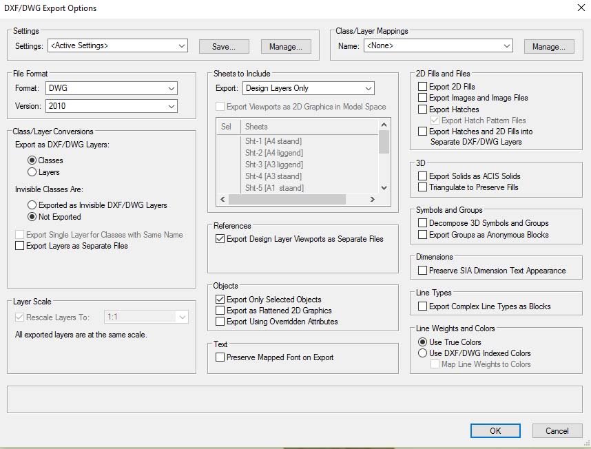
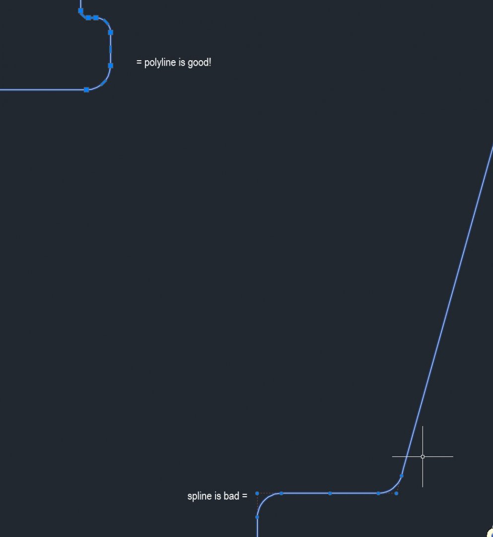
For the production (CNC-milling and waterjet cutting) of several parts I need DWG and DFX-files I have a problem with the exported lines. The exported lines from VW should be (to work properly with the different machines) 'polylines', but sometimes they are 'splines' (see image underneath and the difference between how the curves are drawn). If I convert the splines in Autocad to polylines they get hundreds of extra control points and the different milling/cutting machines aren't able to use those (and the line gets faceted). My workflow: - Draw the model in 3D - extract planar object - change the objects to screen plane - export the selected object to DWG or DFX version 2010 or earlier The odd things is that from different object, but the same file, I get different types of lines in Autocad. Anybody experience with this? Anybody knows how I can export them so i get clean polylines? Attached the different files, if anybody could have a look i would be very happy! (ps I`m not able to attach VW-2017 files on the forum ) export test.dwg export test v2016.vwx
-
@Art VThanks for the tip!
-
@fuge In your case i dont know if the benefits will outweight the big change it will be. I had a look a Solidworks as well. My work has shift from interior architecture to product design / furniture design. The interactive way of modeling and ablity to work with sheet metal is one of the big pro`s you have in solidworks. In VW allot of times it is not possible to change te size of something in a model interactively like in SW. Even annotating an arc/circle/radis in VW is hard if not impossible if it is a solid and not a planar object. If VW could do all this : https://www.solidworks.com/sw/products/3d-cad/solidworks-standard.htm
-
nurbs/line preferences, normals align
Bas Vellekoop replied to Bas Vellekoop's question in Wishlist - Feature and Content Requests
Bump -
fillet edges nurbs
Bas Vellekoop replied to Bas Vellekoop's question in Wishlist - Feature and Content Requests
Bump -
shell tool wishes
Bas Vellekoop replied to Bas Vellekoop's question in Wishlist - Feature and Content Requests
Thanks @kevin for the clarification! You described it much better! And I agree that its bit odd that you have the different options for shelling, extruding, tapered extruding. For people new to VW its hard to understand why those different tools existed. The are probably good reasons for that but i think it would better that there is one extrude tool that gives different options depending on the kind of object you want to extrude/shell. (the same goes for add surface and add solid, wouldn't it be easier if that's the same command reacting differently depending on the 'input') -
shell tool wishes
Bas Vellekoop replied to Bas Vellekoop's question in Wishlist - Feature and Content Requests
I not completly sure i get what you mean, but what I meant: Example: I want to create this image, or rafters underneath a curved roof: If i want to create rafters underneath a curved roof i use the contour tool to get the curves from the nurbsurface or subdivision object. These curves are the middle of the wanted rafters. At the moment the shell extrudes to one side, the in- or outside, depending on wich mode you choose. I would like to have the abilty to extrude half to inside and half to the outside so that the contour is in the middle of the solid that is created. The same for shelling polygons: beside the option to shell to the inside or outside it should have an option to shell to both sides. (At the moment not behind VW so if i didnt explain it clear enough I will create a mock-up of the wanted result, just let me know ) -
Thanks for sharing!
-
After the great release of VW 2017 I'm hoping for some upgrades for the solids modeling (interactive fillet / interactive chamfer / editing history) and nurbs surface modeling (interactivity / joining of surfaces / combining of tools) for VW 2018. I like and use the 'old' modeling tools allot, but they are in some desperate need of care and love. They are not fancy as the latest additions to modeling tools (subdivision surfaces, twist and bulge tools) but because they have a editing history and because the work with basic planar objects that you can extrude its easier to work with real dimensions. The twist/bulge tools and subdivision surfaces are imo more like working with clay, allot of fun, but not allot of stuff is made of clay For example: if I want to model a piece of bend sheet metal, i always draw the side view with the correct radius as a planar object and the extrude it. Or create 2 nurbs surfaces and fillet them with a chosen radius and shell it. I can control every step in this proces and go back. Personally i dont 'trust' the bend tool in VW for this (and it doesnt help you cant go back a step if you want to change the radius). I searched for the several wish lists topics about them and gathered them here. Lets 'plus' this topic with hope it gets priority for the next release (love the new search tool on the forum )
-
- 3
-

-
- vw2018
- solids modeling
- (and 3 more)
-
list of updates would be great!
-
Haha
-
Agreed, but maybe that should be something that is controlled in the viewport options under the advanced button, like merging adjacent components with same fill class. If could give the different classes another 'outline' in some sort of way. +1 The difference between plans and sections is most of the times not that big, true, but I like the idea of having more control over it. If there is a system of turning on-and-off options/complexity like in C4D then we can choose which of the class settings we want to use: only the general old style with 1 fill, 1 pen, and 1 texture, or more complex with a different section style and/or elevation style with the different options for pens, fills etc. Rather have the option and don't use in 80% procent of the times then figuring out a workaround for the other 20% of times I don't know if I like this concept. Its a bit like changing the scale of a hatch in the resource browser that is used in a RW-texture. It is logic that they both change but I can give unexpected results if you don't keep track where and how they are used. In my case I would have a different class for the bench and the wall paneling. The whole kitchen (bench, kabinents, countertops) would have a general class (or sit in a group with a general class) so I can turn it on and off completely, and the materials in the kitchen would have there own class so I can change the appereance/materials. The same for the wall paneling, a general class for the wall and a specific one for paneling 'inside' this class.
-
@Art V Agreed, in Cinema4D you have for the sketch and toon settings a simple, intermediate and advanced 'mode' to change settings. For VW simple it could be as it is now, and advanced would be with all the settings for sections, elevations etc. Or maybe there should be a selection box to turn on specific settings for the different options (elevation / section / plan): for this material I only want to use 'classic VW style' and not those for elevation, but I do turn on the settings for plans and sections. @Tom Klaber Curious: how is having line weights for materials/classes different from how you work now? I'm used to work with specific classes for specifics components in walls and floors etc. So a class for the concrete and a class for the insulation. By doing this they have already a line weight assigned to them and in my case I only get more control over that for the different presentation scales.
-
Past week I was working on a project where i needed to use surface hatches. I think it can be implemented beter. When i was thinking about this i realized its 'bigger' then only the surface hatch part. To be honest i think there should be an overhaul of how classes work an what you can do with them. In general classes should have to ability to work as materials. This would mean you would create a class for every material with al the specifications needed (including R-ratings and other properties like weight/m3 etc.) With the new forum its easier to look for previous comments and discussions about this. I will included these because some things i borrowed from there. MOCKUP AND WISHES: ability to create 1 material / classes that you can set to use different settings for different scale. When you create a viewport (1:10) on a sheet layer that's different then the scale on your design layer (1:50) it automatically uses the properties of 1:10 instead of 1:50 This option could work as class overrides do now, but more automated. For every material you can set Lambda values so you don't have to do that in your wall style. The wall styles gets the options to use the values from your class or material or just use a different value. This should work like the attributes palette works: it can be set by classes, but it doesn't have too. Ability to use hatches and tiles in surface hatches. (I'm never been able to create in a simple way a hatch as I can with tiles) I don't like how hatches work together with textures. I think this should be 2 separate things that can work together but don't have to. It should not be part or your renderworks texture but something you can set separate. Beside that I think its confusing that you have a scale for the hatch in your recourse browser, as well in the renderworks edit texture. At the moment if you change the scale of your resource it changes in the renderworks texure as well. In someway this is logic but it worked unexpected for me. You should be able to change in % the scale of your hatch in the class/material without editing the resource in the resource browser. For a section and a surface we should be able to set different hatches without overrides, so lets split that up in different options. I wanna set the pen, fill, hatch, opacity, scale, thickness separately for: sections plans elevations
- 14 replies
-
- 3
-
-
- building materials
- materials
- (and 5 more)
-
Thanks Jim!
-
Xray doenst work when working with subdivision objects
Bas Vellekoop replied to Bas Vellekoop's topic in Solids Modeling
Thanks for looking Jim -
Xray doenst work when working with subdivision objects
Bas Vellekoop replied to Bas Vellekoop's topic in Solids Modeling
Thanks for looking at it Tim! I will ask Jim if this works as designed or is a bug. If its not a bug i will fill a wish. -
Xray doenst work when working with subdivision objects
Bas Vellekoop replied to Bas Vellekoop's topic in Solids Modeling
Hi Alan, And when you are editing the subdivision, does it then still works? Like in my example? -
Is this intended?