


MaltbyDesign
-
Posts
257 -
Joined
-
Last visited
Content Type
Profiles
Forums
Events
Articles
Marionette
Store
Posts posted by MaltbyDesign
-
-
3 hours ago, jeff prince said:
If you go the data visualization route, there is an excellent tutorial on Vectorworks University where they demonstrate this technique on a remodel project.
"REFURBISHMENT WORKFLOWS: CONSTRUCTION PHASING USING RECORD FORMATS AND DATA VIS"
Sadly, I can't find a tutorial by this name. Are you able to share a link?
-
1 hour ago, jeff prince said:
If you go the data visualization route, there is an excellent tutorial on Vectorworks University where they demonstrate this technique on a remodel project.
"REFURBISHMENT WORKFLOWS: CONSTRUCTION PHASING USING RECORD FORMATS AND DATA VIS"
Thanks for that, Jeff. I'll go have a look at that. This seems to be a really logical way to control visualization for phasing.
-
 1
1
-
-
24 minutes ago, michaelk said:
Here's an example with walls. Keep in mind that this works with ANYTHING (…almost!)
That looks interesting but what I don't understand is how you apply the existing, new and demo characteristics to the wall. I see in the Properties Data tab you have the three phases in a drop down. How do I do this with my own wall types? Is there a tutorial on this that you could direct me to? I'm using VW2022.
-
29 minutes ago, michaelk said:
Your signature says you're using 2015. Is that still true?
No. And I can't see where to change my signature. This came up before and I checked my profile settings but don't see it anywhere. Used to see it under my name but something appears to have changed with how the forum is set up.
-
15 hours ago, michaelk said:
In the viewport set the Detail Level to Low. All the walls should lose their components. As far as I know that's a VW-wide setting that isn't editable. I know you can't change it on a per wall style basis.
I use Data Visualization to change the graphic attributes per viewport (white fill for existing, dark fill for new, no fill + dashed line for demo). The easiest attributes to use are a record format attached to the walls, but you could also use class.
Thanks for this. Where can I find out how to implement Data Visualization? That sound like what I need; a way to easily differentiate between existing, new and demo.
-
When I model walls, I like to create wall types made up of components which can be seen on plan but for some presentations it's nice to show walls as solid black. I thought there was an easy way to do this but I can't seem to find it. Any tips or directions to a tutorial that explains how this can be done?
Thanks in advance.
-
I can! So that took me on a hunt to change units on the computer itself which is exactly what was causing the problem. Thanks for your help, Pat.
-
On 4/8/2022 at 5:10 PM, Pat Stanford said:
That sounds like a problem with the printer driver not with VW.
Try going to System Preferences:Printers & Scanners and see if there is an option there to turn on other paper sizes.
Or download and install a different printer driver.
I set up for 'Any Printer' so I don't think printer drivers come into it. However, the printers I do use are set up for imperial sizes. Not sure why I can select from both imperial and metric sizes on my iMac but my MacBook Pro is only showing metric paper sizes.
-
I have units set to imperial and when I go into File>Page Setup>Printer Setup only Metric paper sizes are given as an option in the selection tab. Okay, so go into Manage Custom Sizes and hit + to add a new sheet size but only metric shows as a size option. I don't have this problem on my iMac in my home studio, just on this new work laptop. I can't figure out any other location where I can change units other than File>Document Settings>Units. What am I missing?
-
@Benson Shaw thanks for the suggestions. I don't think it's any of those but I'll double check.
-
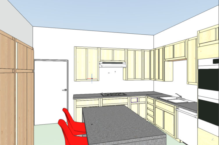
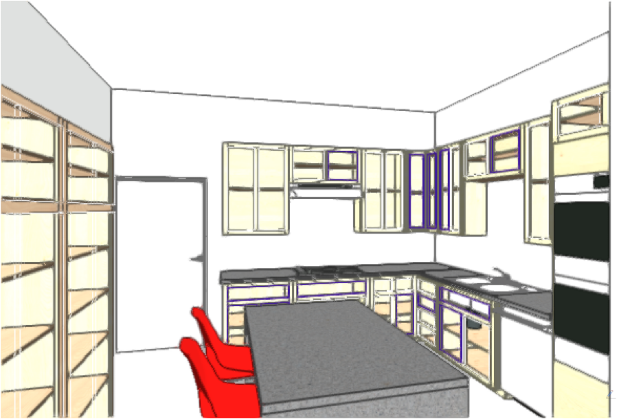
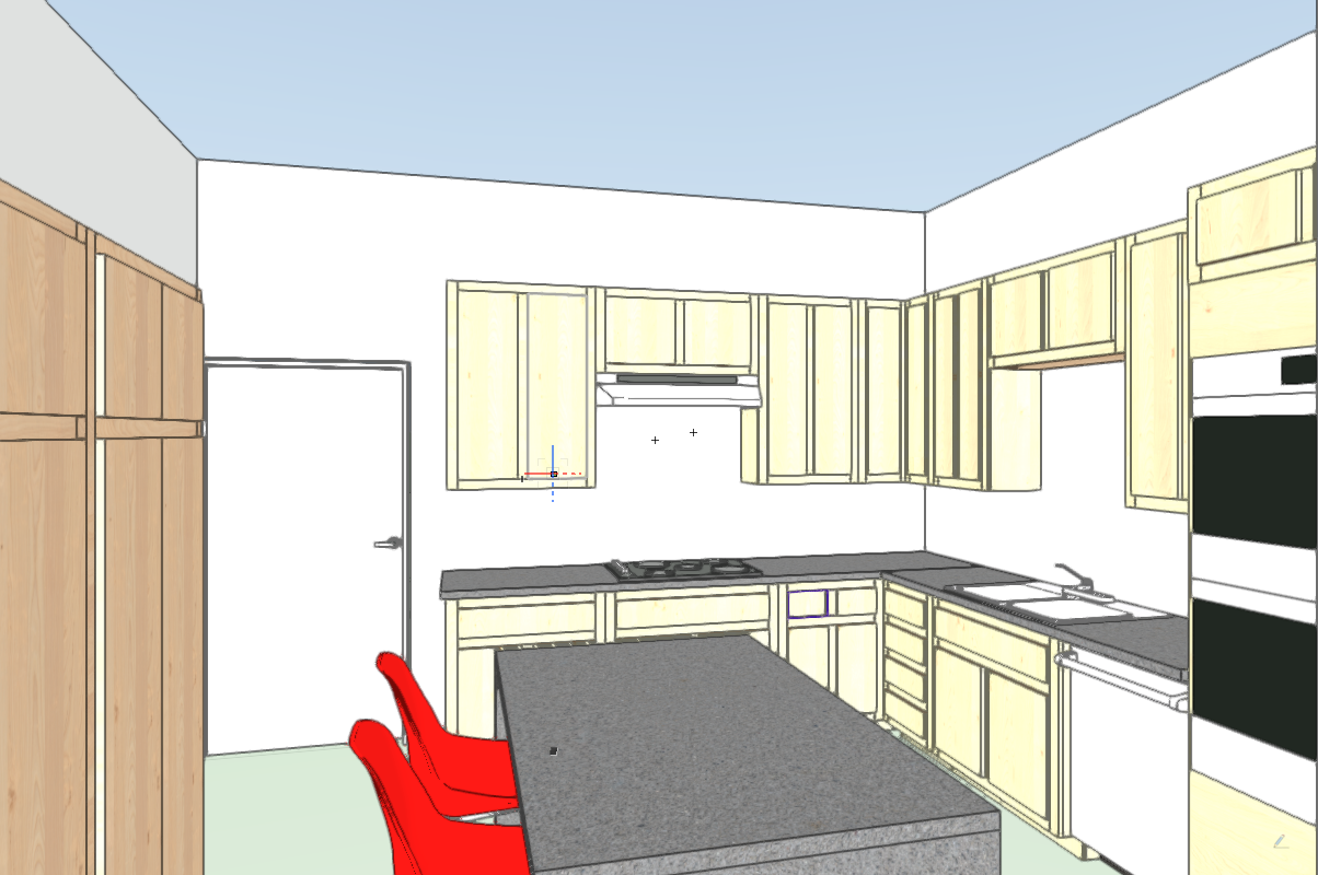
Cabinets appear to have portions remaining in wireframe when 'shaded' in a 3D view. Restarting VW seemed to address this. When I save a view the rendering appears as it should but when I want create a viewport of this saved view to add to a sheet, the resulting rendering is partially rendered with the doors appearing as wire frame. That is not rendering like the rest of the cabinet. Restarting VW didn't solve this. The first image show a screenshot of the saved view which renders properly while the second shows the viewport on the sheet, on which door faces aren't rendering. Any ideas how to fix this? Is this a software problem or user error?
Monterary v12.2.1
MacBook Pro (14-inch, 2021)
M1 Pro
32GB memory
-
Thanks very much, Pat. I'll see if I can't eliminate those. It's a drawing that I inherited so am sorting out a few issues.
-
Thanks Pat. The viewports on that sheet are fine. The problem is when I try to create a new viewport from a design layer. I'm using VW2022 SP3. My signature hasn't been updated in a while.
-
2 hours ago, Pat Stanford said:
Post or DM the file or a link and I will be happy to take a look.
Thanks! I'll DM the file to you.
-
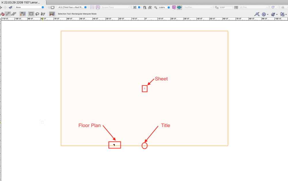
Select All and then Zoom>Fit to Objects was one of the first things I tried. I can't see any reason for the giant bounding box.
-
On 10/13/2020 at 3:02 PM, Pat Stanford said:
Without a crop the viewport will extend to the limit of all the objects in the drawing. Check your design layers for objects out at the limits of the viewport.
Sorry to revive this topic, but I'm suddenly having this problem as well. I turned on all classes and layers to be sure there was nothing floating off in space to dictate such a huge bounding box. I created viewports the other day without having this happen but now I can't see why this is happening.
-
@techdefThanks for the clarification. I'll give that a try. I was trying to get the 'fascia' wall to follow the roof but that wasn't working.
-
@techdefwould you mind sharing a screenshot of your Insertion Options in the edit wall style dialogue box? I've got the wall as fascia part but can't get the wall to follow the top and bottom of the sloped roof. Thanks in advance.
-
Thanks for the alternate approaches. I just wish that the built in tools worked as expected without having to find workarounds.
-
I often use the Create Roof tool to quickly create shed roofs, done by converting 3 of the 4 sides to gable ends and the low side of the roof remaining an eave. Inserting a fascia will only add a fascia board to roof edges that remain an eave. Any edges of the roof that have been converted to a gable end will not receive a fascia board. This seem like the most basic of flaws in the software, particularly when trying to quickly model a design idea. Am I missing something? I don't think this should be a difficult task.
-
@Ben Beaumont I just wish that the whole setup was more intuitive than it is. Considering how much discussion and confusion there is around storeys, layers and levels suggests that the user experience could be made less complicated than it is.
-
1
-
-
@zoomer when I was playing around with TM, the first time I imported a model it was nowhere to be seen. Discovered that it was because I create my site model with actual elevations for the grades and import my building model which I build with the main floor at elevation zero. TM imported my model at the elevation of my site model (+760'-0"). So I ended up creating a separated model file with the site model set to zero before exporting it and that seemed to work. What I don't like is how the model edges look like cliffs when imported. Not sure what, if anything, can be done about that.
-
@Tom W. Thanks very much. I was looking at that but didn't see the "Set by Image" button. I was also to edit the surface hatch as well. Thanks again.
-
I'm using the standing semimetal roof material MT on my model and it appears at half the scale showing seams at 6" apart rather than 12" On walls, it looks like I can scale the spacing up in the OIC - Render tab. But where I've applied this material to a roof, I can't see any way to adjust the scale. Why doesn't the material insert at the correct scale to begin with and is there a way to adjust to the correct scale on the roof? I should note that on one of the wall, adjusting the scale won't work for some reason, despite being identical to the others that dis scale.
Thanks for any thoughts on how two fix this.

Easy way to show walls with black fill for 2D sheets?
in Architecture
Posted
Thanks very much, Jeff!