


J. Wallace
-
Posts
702 -
Joined
-
Last visited
Content Type
Profiles
Forums
Events
Articles
Marionette
Store
Posts posted by J. Wallace
-
-
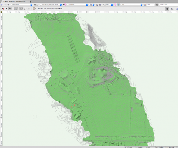
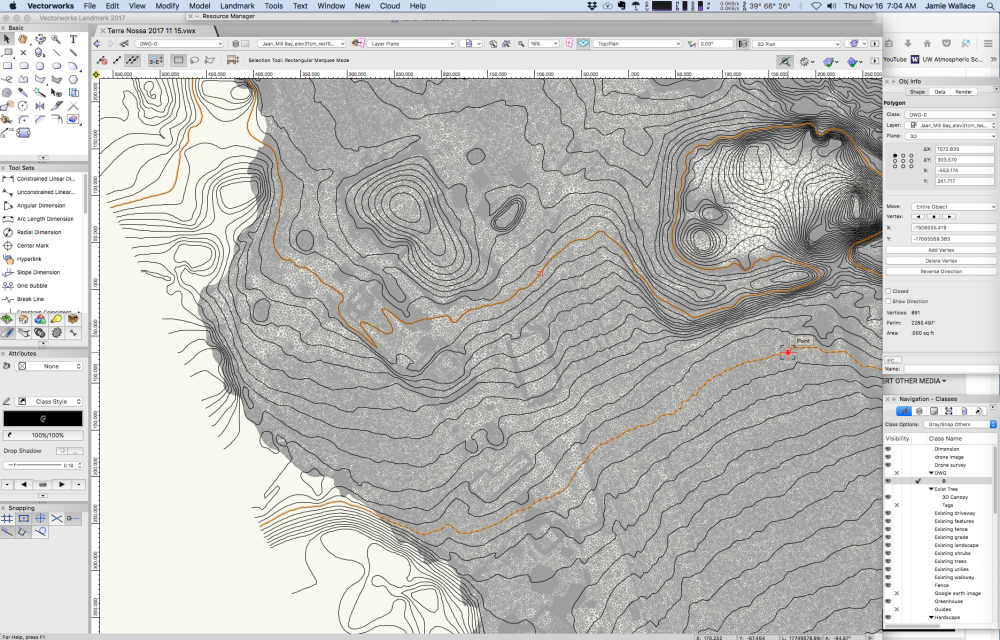
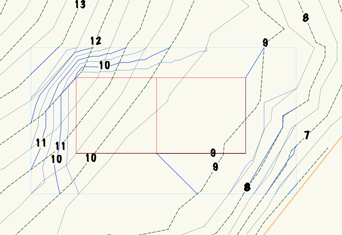
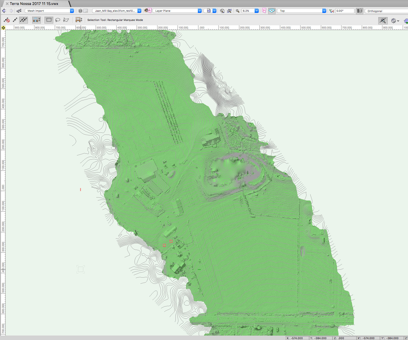
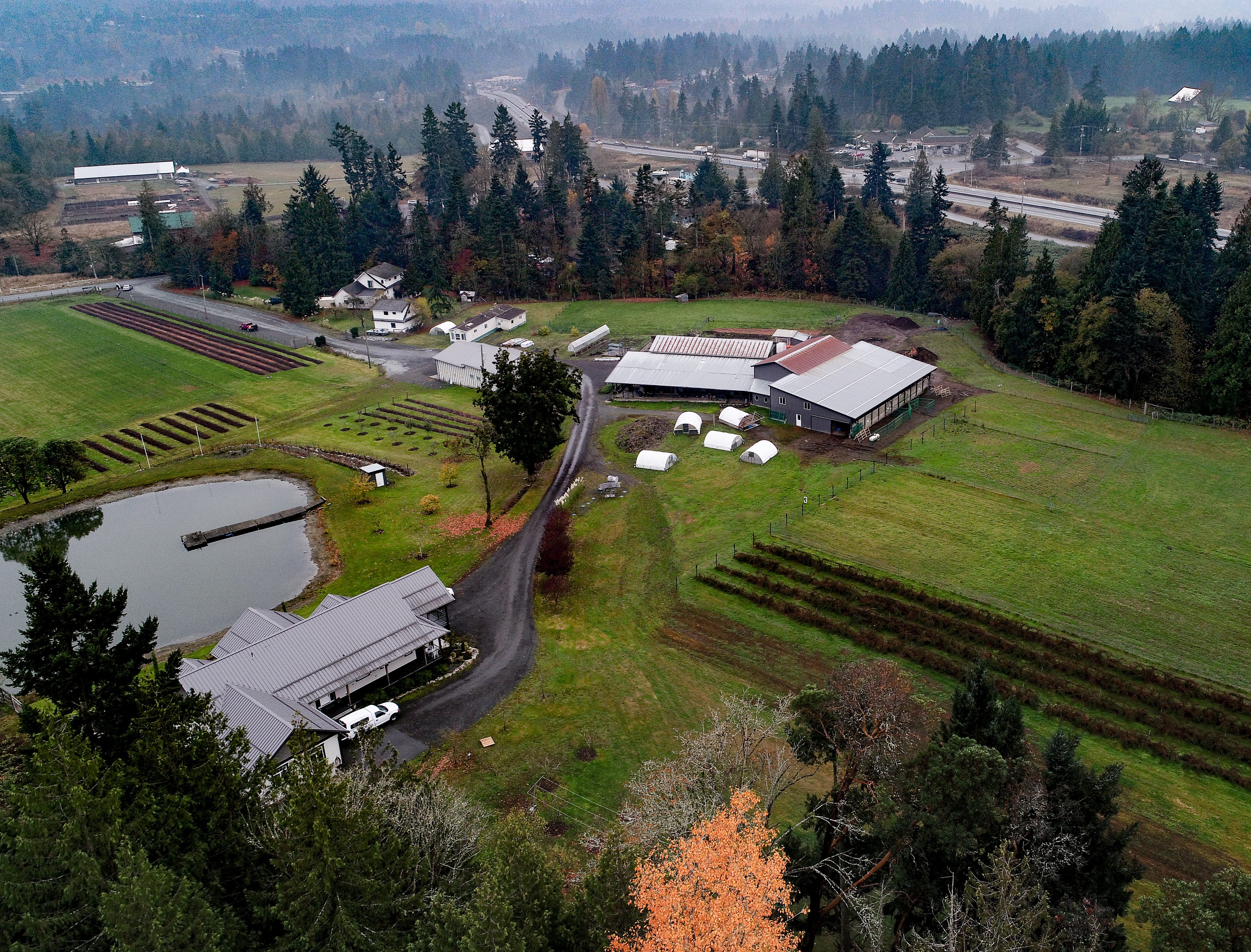
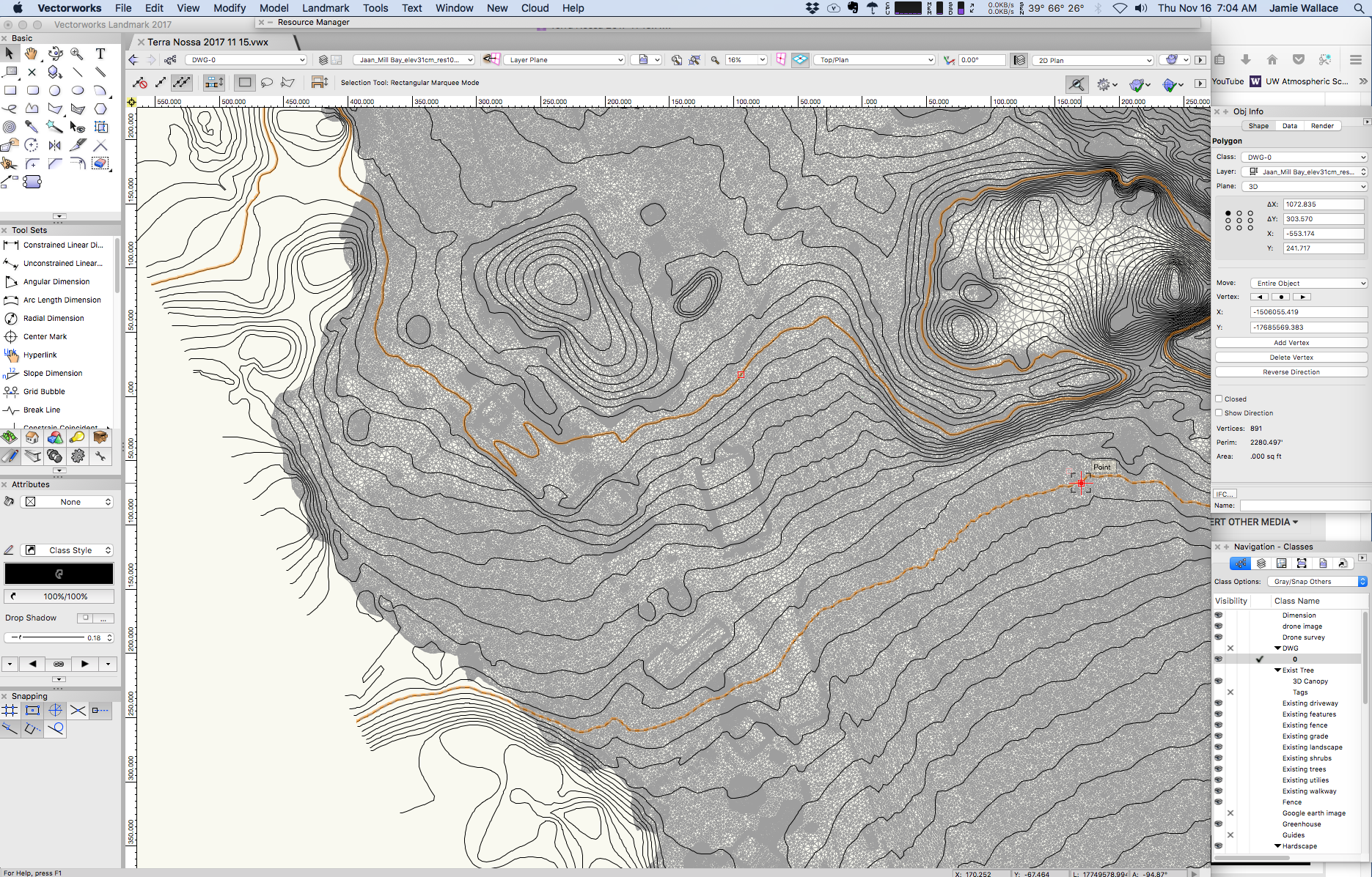
Hi all. An update to this post. I had the drone survey done, some lovely images have resulted from this which is a bonus. I have imported a .dxf contour file along with a mesh file which really bloats out my file to around 870 mb...I should be receiving a shape file of the contours today which will provide elevation data with the 1' contours. So here's my proposed workflow to get started, please chime in with your thoughts:
- Import shape file and convert these contours to 3d polys...might consider converting to nurbs first, then 3d polys in order to reduce the vertices, as you can see in one image I have over 800 vertices on one contour line., 277 polygons in total which could give me over 200,000 vertices in my site model.
- Create site model then apply some pads to the areas below farm buildings and place massing models to represent them.
- I'll use the mesh as a guide to applying infrastructure to the model such as roads, fences, exiting plantings. I'll probably delete the mess once this is complete as it has increased the file size by 800 mb.
- At this point I should have my base map or existing site model complete.
- I have access to a high definition .tif image but it's 595 mb in size and doesn't seem to load into VW or any other software I have. Not sure what the upper limits of image importation VW has?
Thanks for your thoughts...this is the first time I've used a drone and hopefully not the last.

-
Thank you @Art Vand @Benson Shawsome really good information. After some back and forth with the drone operator it looks like I can get a .1m level of accuracy with regards to elevations which I'm happy with. The operator will provide me with 1' contours which works for me, I could get this geo referenced but I'm not sure that is important.
Cost isn't too bad, $1250 CAN to survey 6 acres, $200 extra for Geo-spacial or GPS points and I get some high definition images to boot. I'll keep you posted as to how this unfolds.Out of interest I asked a surveyor a rough ball park to survey the property in a traditional manner, he stated it would be $2-3,000
-
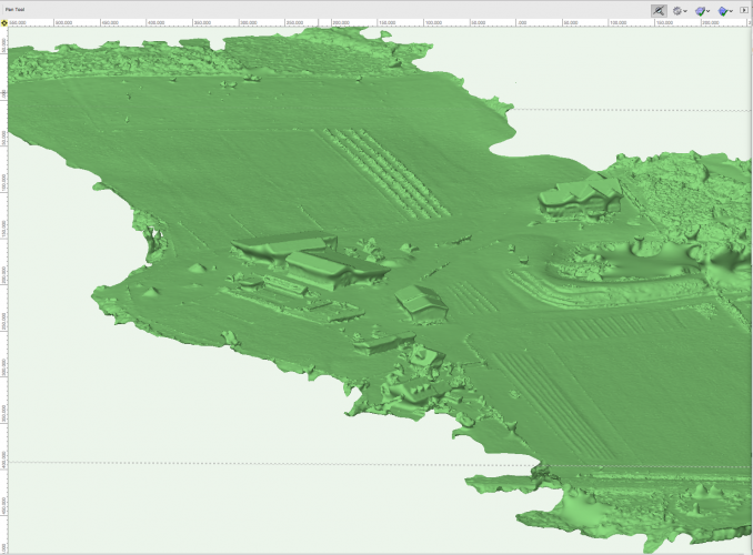
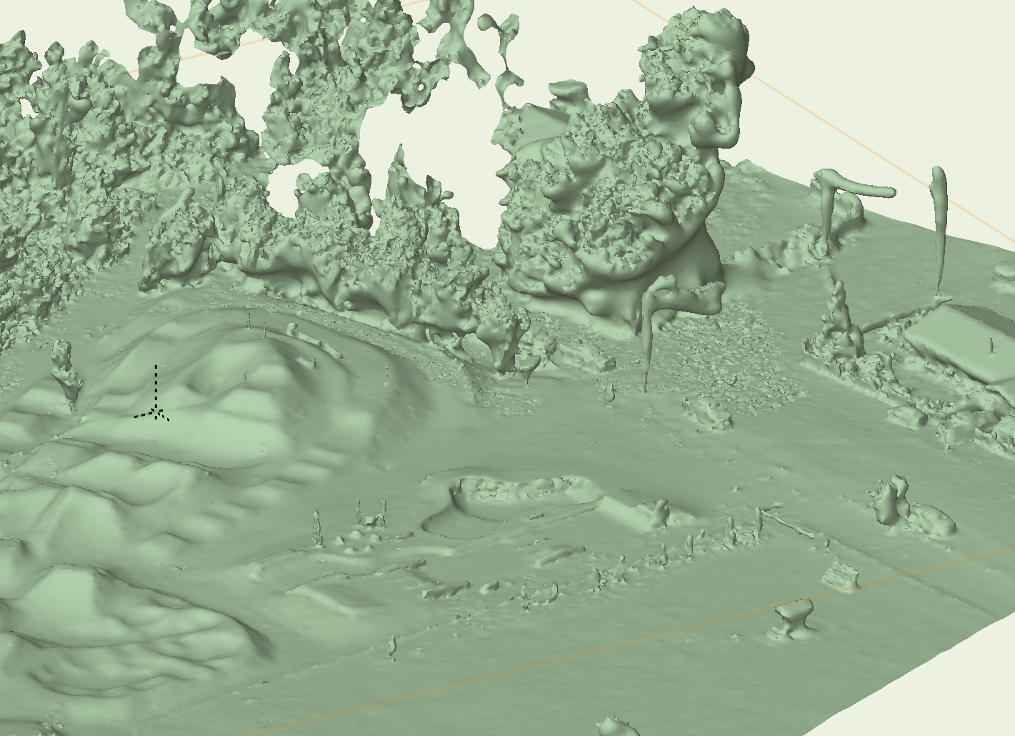
As a continuing story on the Drone import data question I contacted another firm today and was thrilled to see that they can provide me with the contours I need to construct a site model. Waiting on the level of accuracy, but hoping it will + - 1'. Interestingly I can also import a mesh object and was given a sample to look at, can anyone tell me if this mesh object is usable within a site model? I did note that the texture import failed. Also the file is 430 mg which is pretty big so I'm not keen on working with a slow, clunky file.
@Art Vyou might be interested in this.

-
One of the simplest ways to do this @Buzchevais to just duplicate the line you wish to copy. If you click the and hold down the option key you'll duplicate the object. You can also rotate any object using the rotate tool.

-
Thanks @Art Vsome great info. Looks like I wrongly assumed good accuracy given they were generating up to 1' contours. Thanks for that.
I've sent along some questions to the drone pilot that I'll pass along once I hear back.
Take care and thanks again Art V
-
7 hours ago, Art V said:
Coincidentally I happened to be at a user day of GlobalMapper (a GIS program) earlier this years where one of the workshops was from a company using drones and Agisoft Photoscan to create terrain models.
One thing they use are ground beacons to determine accurate elevations as these points serve as a reference for how far above the ground the drone is flying at any given point in time for improved accuracy.
It worked really well but it does take some time to render the features etc., but it is far more cost effective and faster than satellite data for relatively small areas to get an overview of the current situation (i.e. as of the of flying the drone) compared to commercially available options which usually have some delay between photographing and updating imagery.
So in this case it really depends on how they did the photographing and georeferencing, i.e. only use the drone's GPS or also ground beacons to reference for elevations etc?
Not sure of their claims on accuracy other than they claim to produce 1' contours.
-
7 hours ago, Art V said:
DSM = Digital Surface Model which shows elevations at the heights of e.g. top of buildings, trees etc.
What you probably need is a DTM = Digital Terrain Model , i.e. elevations without the objects as trees etc.
So the big question is whether the contours would be useful for your purposes anyway.
Luckily the site is open as it's agricultural. Some trees on the property boundary but for the most it's open.
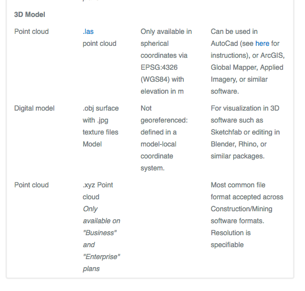
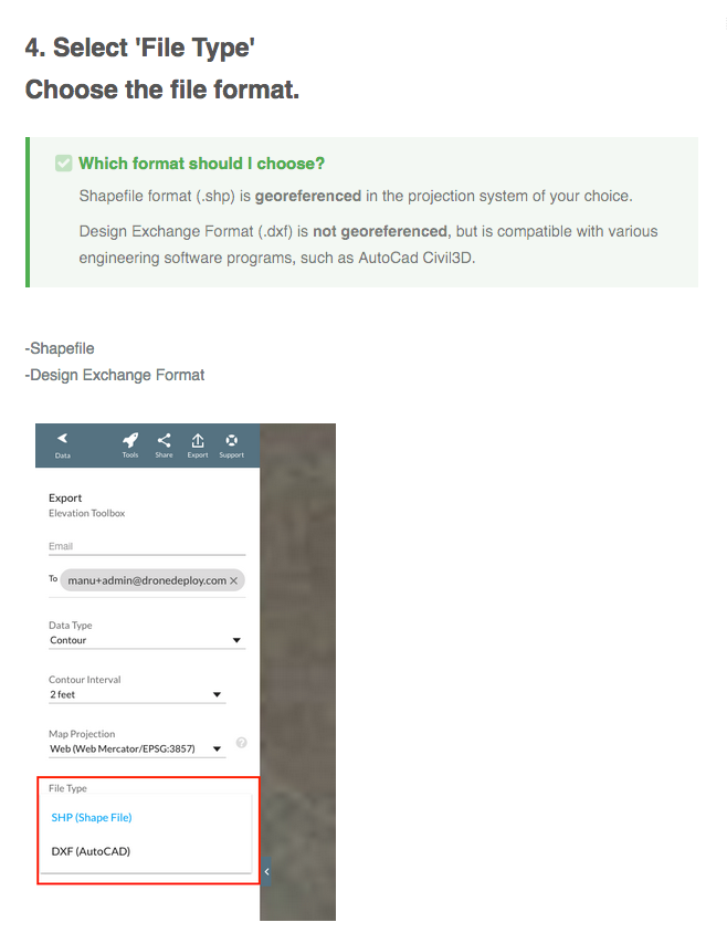
7 hours ago, Art V said:Assuming you still want to use the data and you need contours, then by all means do select shapefile as it will contain the georeference information and should reproject to your desired coordinate system better than a dxf. (BTW, AutoCAD Civil 3D can import shapefiles so the argument for DXF is a bit inaccurate in this case, it only applies for CAD programs that don't support georeferencing. Because VW does support this in Landmark and Architect my suggestion would be to always use shapefile over dxf if possible if georeferencing is used)
The other option is to use the XYZ points to create the site model instead of contours, but the Z value will most likely be the top of the trees, buildings etc. and not of the ground given their comment they are providing a DSM and not a DTM.
So again usability of this data is the big question to answer first before spending the money.
This makes sense, thanks @Art Vfor that. A few weeks back I had some Lidar data sent to me (after it was manipulated a bit) and this was in a shape file. It was great to see all objects associated with an elevation, so this would be great. The drone app that I would have to use to access the information does produce 3d DTM but I'm not sure I cold actually utilze these in VW. It's going to be a bit of a wait and see with this service I think. Based on your comments I feel confident that I'll be able to extract some useful information.
Thanks again.
-
Hi Everyone
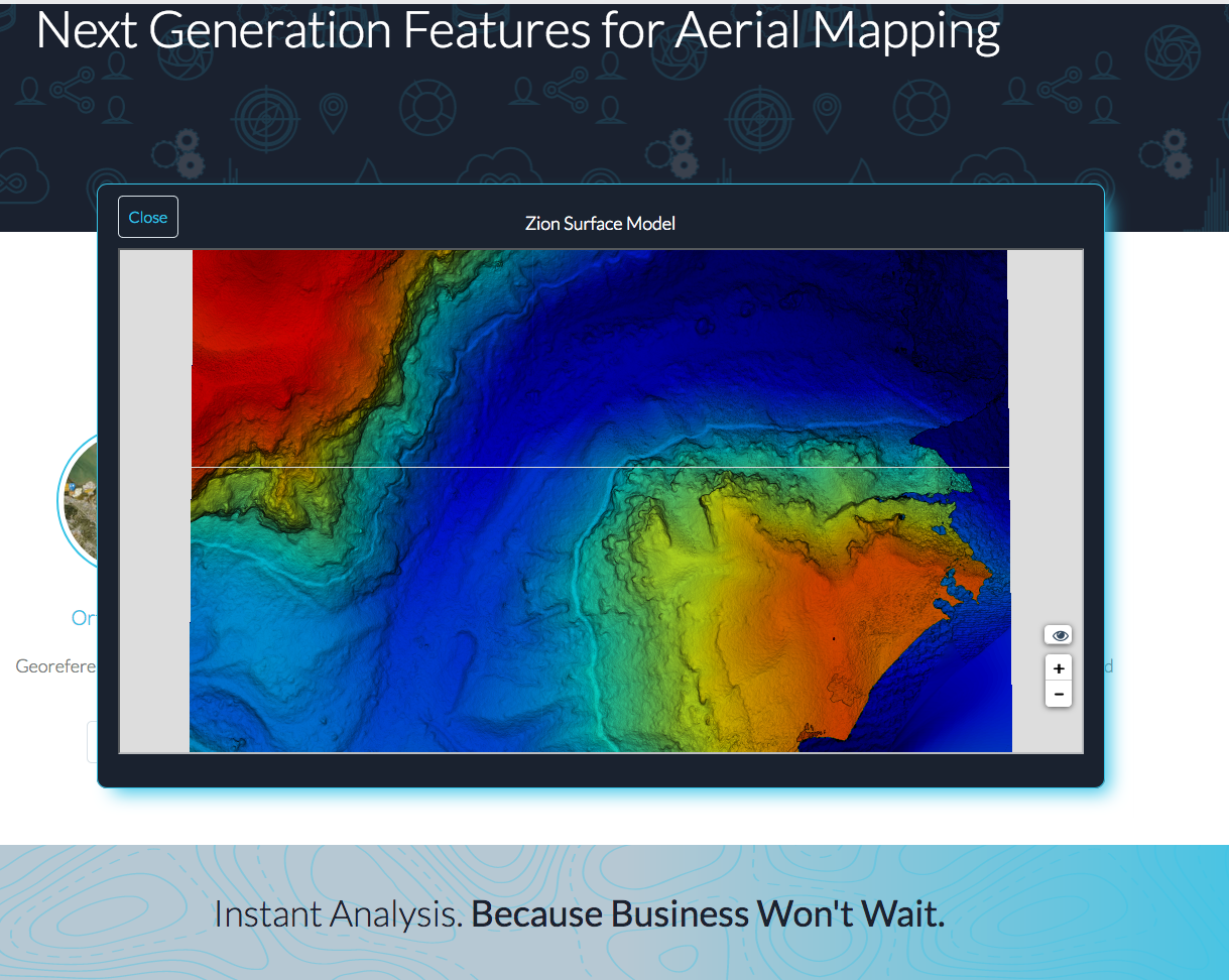
I have a question here that I'm hoping someone can help me with. I'm starting a project on a piece of agricultural land (creating a agri-tourism concept) which is about 10-15 acres in size. I'm in need of some accurate elevation data as well as some high definition images (overhead), a drone is one obvious choice. I have contacted a company that will fly a drone and collect data for me at a pretty reasonable price when compared to traditional surveying. This drone pilot uses a web based software to share this information with his clients, which I think is a pretty sensible approach.
My question is whether I can this exported data and make it useful within VW. I have provided a couple of shots from the drone Deploy website and I'm pretty sure that importing .dxf will give me some contours that I can work with. Can anyone confirm this? The service is $750+ 100/month for access to this online software which I imagine I'll use only once.
I don't see the high definition image being an issue, but I'm unsure of the 3d data.
Thanks in advance for any assistance.

-
The first thing I would look at is your class and layer visibilities within each VP.
-
Does the grade tool not work for you?

-
@RossfordGood idea, hadn't thought of that. I usually make all my site modifiers by converting them from polylines.
So your suggesting that the polyline is then offset (say 1mm) then add surface?
I gave part of your suggestions a shot, made two rectangels which snapped together,>offset 1mm> converted them both to site modifers (pads on the same elavation)> then through a grade limit around them. It works. How do you think the add solid would help?
Given that you can't have site modifiers such as pads touch one another shouldn't there be a mechanism in place to prevent this like a default 1mm offset?

-
@zoomerI would love to see an option that when placing a pad or texture bed beside another existing pad or texture bed that the boundary would offset automatically (lets say 1mm) to avoid overlaping site modifiers. The offset would become the new snapping point and would save some time and frustration.
-
I don't edit the contours I do add 3d loci as suggested in @Benson Shawvideo. Once the contours have been fixed or smoothed I'm ready to start applying modifiers.
Your right Zoomer that this type of work is a bit tricky and your never confident of your outcome. When it does work it's wonderful.
PS on a side note I'm finding my work is requiring good elevation data on 5-30 acre sites and I've been looking into Lidar data which is free for many areas on Vancouver Island (where I operate), it looks pretty promising and can be much better than traditional survey data. I'll post on this later today.
-
@zoomerI've never placed a grading limit on the property line, interesting. I understand that you can place multiple grade limits within each other and I've done this before.
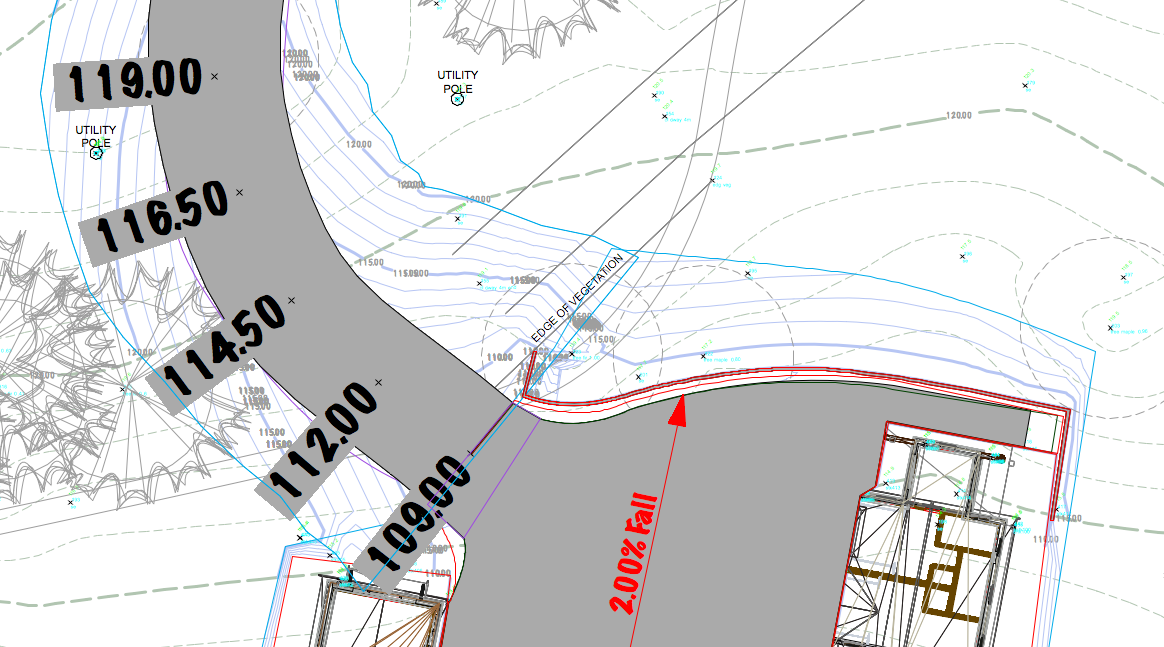
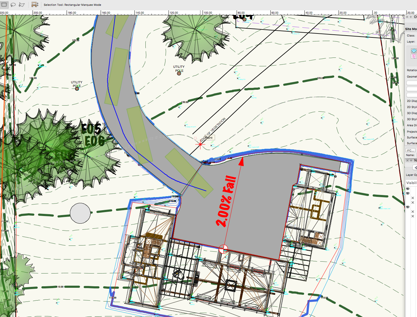
I would love to see VW provide an option when creating a pad to create and offset of 1mm to an adjacent pad. I find that when I'm working on site models that pads are often located close to an adjacent one as seen in the image below.
I recently did some work using the Nurbs road tool and set the grade limits to create a 3:1 slope which can be seen in the image. This is a huge benefit for anyone in land design.
Zoomer my understanding is a pad forces contours around itself and this is expressed in how the grade limits are set.
-
Thanks everyone for your help. It turns out that the road played a big part in this. I fixed the issue by duplicating the road reduced the length by 2' or so. Pasted it back in, deleted the original, made some adjustments to pads and grade limits. Turns out the Nurb roadway has it's own built in grade limit so I left that alone and yes it did overlap the other grade limit site modifier. All is well and thank you everyone for your help.
-
I'm hoping that one of the site model genuises like @Benson Shawmight have a work around for an issue I'm having.
I have a small site model which I'm trying to apply a road concept to. Using the NURBS roadway tool I have selected stations and adjusted the height of the road which has worked out really well. For the last couple of hours I've been trying to fix a challenge I have were the roadway and a pad ( entry parking area) meet up. The roadway only seems to funtion correctly with a 1-2' offset grade limits enabled, the trouble seems to be the grading limits on the pad and the road intersect and are causing this issue. If I delete the road and re-render the pad sits as expected.
On a side note this tool, the NURBS driveway tool, seems to have a few imperfections. If I create a larger offset on the grade limits setting I end up with some strange artifacts (spikes 8-10' high).
Any suggested work arounds would be great...thanks.


-
Mark
in Site Design
@mswanboroughimporting a dxf/dwg file is super easy. Do you have the file or are you looking or it?
I'm not sure what comes with the student version of Vectorworks. Not sure if you've checked this out?
http://www.vectorworks.net/support/downloads -
There are a number of things that can cause this.
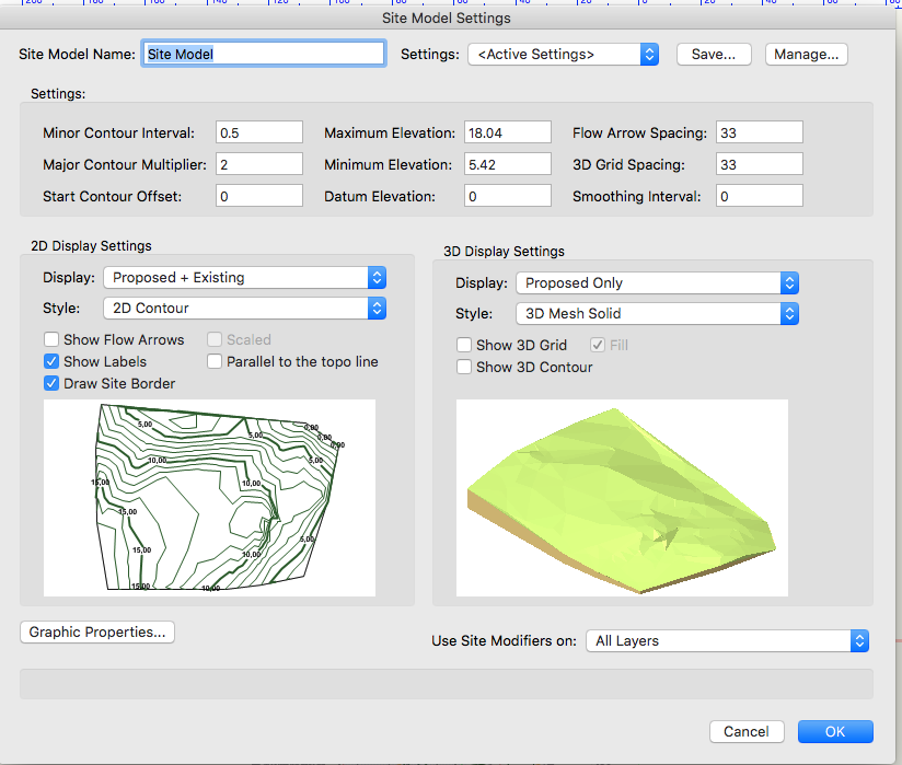
- Check that your site model settings have the correct use site modifiers on...can't tell you how many times I've placed a modifier in a drawing and this setting was incorrect.
- Check your grade limits as these will dictate how the grades interface with the modifier.
- Also take a look at your 3d display settings, does the modifier apply to the proposed?
A place to start, let me know how you make out.
-
I'm not an architect @zoomerhowever I usually build the model and drop in any structures. Exact elevations are not as critical for me as others but when a floor height is given, once the building is placed I usually select a front or rear view, select the building and set the floor to align with given height using place by points. Probably a bit rough for your application. Not sure of your second question as I haven't had to geo reference anything yet.
-
@jmanganellithanks for the reply those look very helpful. It looks like converting points to something useful will require a lot more work than I imagined.
Thanks again.
-
Hello
Just wondering if anyone has any experience working with Lidar maps or .las files. I imported a .las file via import>Import point cloud and it worked flaslessly. Now I have over 11 million points...yikes.
Not sure how to move forward with this as I'm hoping to get some contour information out of the file but I'm thinking VW alone might not be able to do this. Any comments are much appreciated. Thanks

-
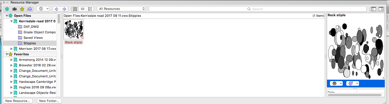
Hello all. Question for you regarding stipples. I have struggled with how best to apply a stipples which has been previously saved.
Once you have a saved stipple can you not apply this to any polygon or polyline much the way you would apply fill?It doesn
I'm sure it's an easy process which for some reason I'm missing.
Thanks.

-
 1
1
-
-
55 minutes ago, zoomer said:
So what I normally need for my Architecture is just :
1. a)
Simple Cut Outs for Buildings,
just so that there is no terrain in my lower Stories Interiors, Terrain untouched.
(Pad + additional Grade Limits ? or Solid Subtractions ?)
Yes that's what I do. If you create a pad you can offset this(duplicate) 1mm or so to make it a tight cut. Haven't needed to use solid subtraction
55 minutes ago, zoomer said:1. b)
Cut Outs for Buildings,
maybe some slight height changes where the terrain touches the Building
(Pad with Retaining Edge sent to surface ?)
I don't use the retaining edge very much as I'm usually placing a retaining wall if needed
55 minutes ago, zoomer said:2.
Streets with Pedestrian Ways,
visible height level differences or curbs recognizable.
(Street Tools needed ?)
This is were it can get tricky matching up different pads that intersect. Hopefully an improvement coming with this one day. I often have to use 3d polygons to hide or mask imperfect pad intersections
55 minutes ago, zoomer said:3.
Some proposed level or slightly sloped Areas,
for Parking Lots, Walk Ways, "Hardscapes" or Furniture,
that blend back into existing terrain over a controllable distance in a nice "tangential" manner.
And these have to be edited easily when changes occur.
You can just place slope on your pad, this is one big improvement that has been made over the past few years.
Good luck with this @zoomer
-
3
-
-
Hey @zoomeryour might want to check out this thread. I find texture beds tricky and you have to follow (at least in my experience) a given procedure for them to work.
Your right that the grading limits are critical but give you lots of choice how the pad and existing terrain interface.
Hope this is helpful.

Can one import a mesh object and use this within a site model?
in Site Design
Posted · Edited by J. Wallace
An interesting update. It looks like the original shape file I imported has 3d data on it even though it does not show that is the OIP.
I converted these to 3d polygons and they had z information..site model is made...that was easy.
ps file is now 940 mb in size mainly due to the mesh objects