Laura Stone
-
Posts
178 -
Joined
-
Last visited
Content Type
Profiles
Forums
Events
Articles
Marionette
Store
Everything posted by Laura Stone
-
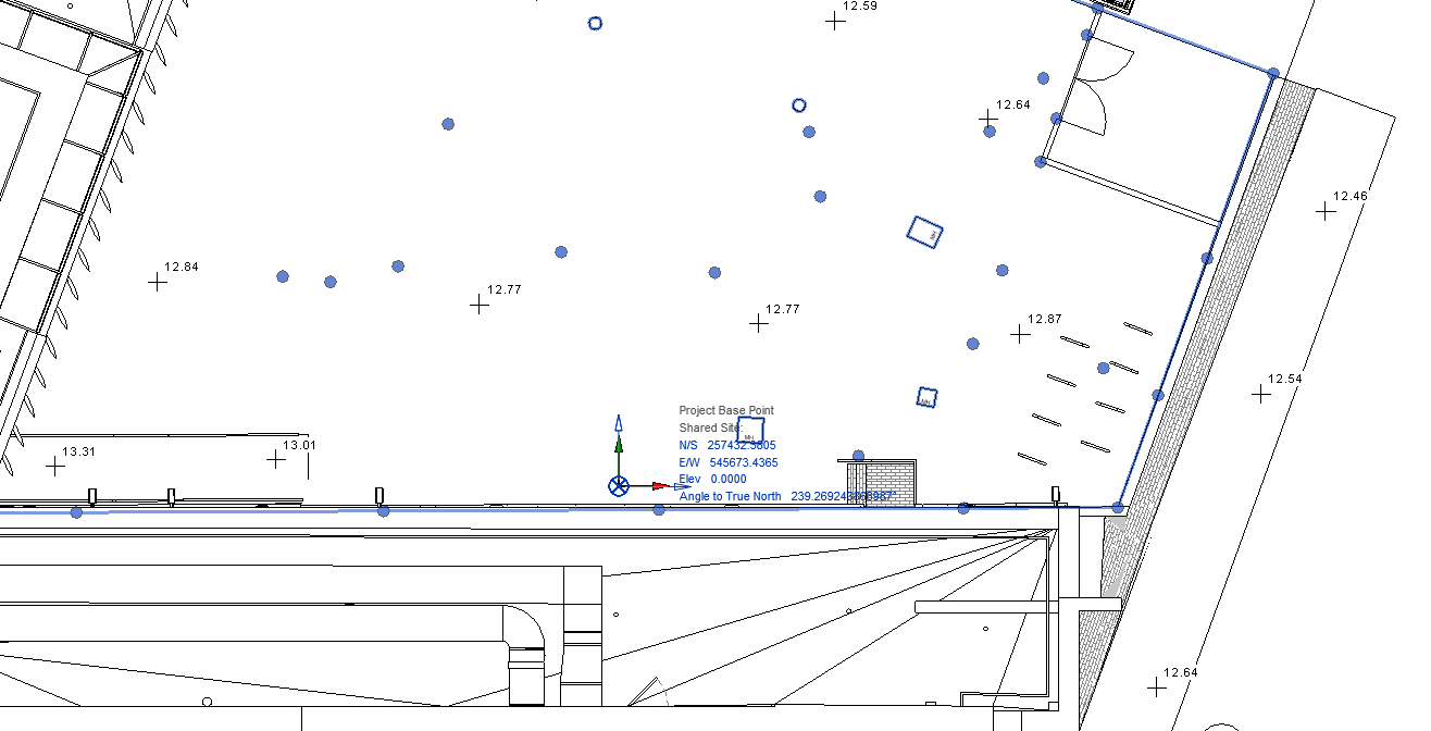
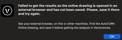
I am trying to do some tracking in Autoturn. Although the offer of lots of vehicles expired at the end of February they are still all there to choose from and use. Unfortunately once the tracking is done and I press 'close & get analyis' as usual I get the usual VW dialogue but then the attached message. There is nowhere in the Autoturn window that I can find to save a file, and I've never had to do that before. Any ideas?
-
It would be very useful if the parking tool had the capability to project lines (in a width) onto the surface of the site model /landscape area/hardscape so that spaces can be seen in 3D. At the moment some pretty unwieldy workarounds are the only way to show parking spaces. Would also be good to have the option to add a hatch to the accessible parking aisle and an aisle at the rear of the space. Again both must be done manually at the moment.
- 1 reply
-
- 2
-

-
Hi Sorry, I think I confused things. I haven't been given an IFC file, only a native Revit file. I am pretty certain the Revit file was not georeferenced but I had also been given a 2D dwg that was aligned north. So I imported the Revit file, picked up everything and aligned it with some of the 2D geometry so it was aligned north and then adjusted the user origin so that the internal origin matched the Revit internal/survey origins (both in the same place). After that I enabled the georeferencing and entered the co-ords for the OS datum and that was spot on for the imagery, so I'm pretty sure right. BIM meeting on Monday so no doubt I'll find out if my Revit and IFC exports matched up.
-
Thanks for that, that does work, bit tricky on the steep bits but preferable to the alternative! Laura
-
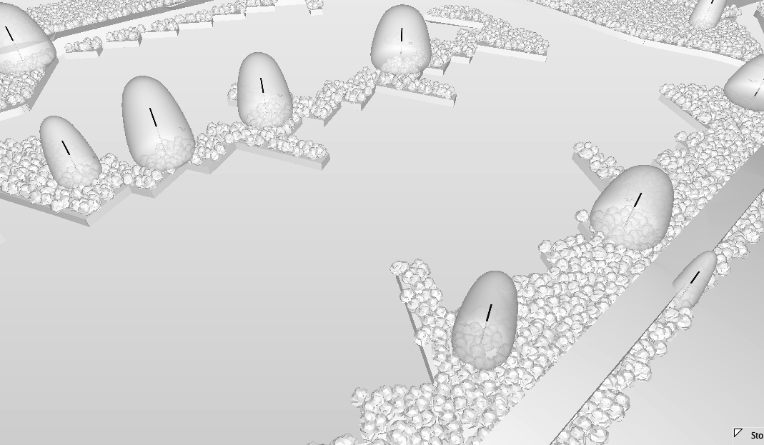
That's very good of you. Hoping to avoid laboriously dropping a 3D locus onto each relevant vertice. Here's a file. Laura Surfaces.vwx
-
I have some mesh objects a bit like hardscapes imported from Revit, unfortunately with a thickness, so levels are replicated on the underside. I think I know the answer to this, but is there any way of picking up the top surface only to get information for a site model? Laura
-
Thanks for all this, a new one for me I've been given a survey in Revit and everyone else is working Revit so I have to tie in with them rather than vice versa (Revit-centric BEP was already written). So I got the Architect to move the project base point to the internal origin/survey point because previously I only had co-ords for the PBP and no way of knowing where it was! So now I have the georeferencing and co-ords set up, but when I tried with the angle to true north shown in georeferencing it went very wrong. What I ended up doing was rotating the drawing north with the same internal origin and am hoping that will make my exports match up. Still a bit of work to do before i get to that point.

-
Bit of a bump here but do you know which of Revit's origins is the one that needs to align? As far as I know there is a project base point, a survey point and an internal origin and they may not be aligned with each other.
-
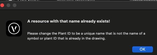
I think maybe what's happening is when I change the Plant/ tag ID and then try to use Plant tag/ID as the name formula it sees the name as being a duplicate of another resource i.e. the plant/ tag ID. If I first change the plant/tag id and then save and change the name manually it says eg. CorSan-2. This didn't happen in VW2023
-
Hi Katarina Sorry this has taken a while, but I can change the latin (botanical) name, it just seems to be the plant tag/ID that it doesn't like. I can edit the plant style name manually in the resource manager but not the plant tag/ID. I've tried it in a brand new drawing with nothing else in it and it still happens. Laura
-
OK Problem solved - When I'm asked to do a few options I usually set up a set of 'alt' layers with different layouts. It looks as though VW doesn't like to have parametric objects in the same place on different layers. Deleted the 'alt layers' and it's behaving fine now.
- 1 reply
-
- 1
-
-
This was happening in v2023 as well, but when I go to move a vertex on a very simple L-shaped hedgerow it is taking a huge amount of time, just clocked 90 seconds to move one vertex. If I make a brand new file with just a simple site model and a hedgerow it seems to be fine, but with more complex ones there seems to be a problem.
-
Hi Pat, I made up a ridiculous name to make sure there wasn't any resource with that name, this is new in v2024. Laura
-
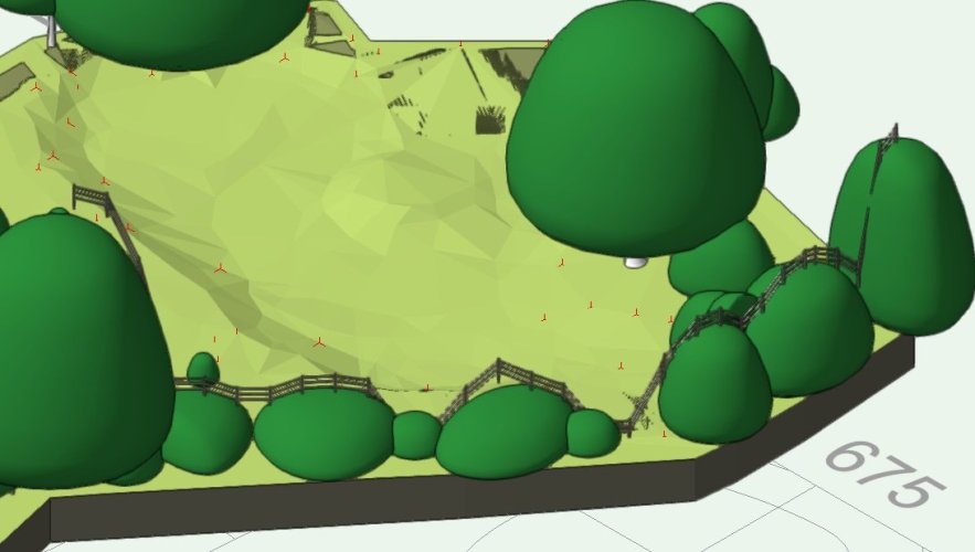
Amusing results of using the gravity mode before selecting classes!
-
If I duplicate a plant style and edit it doesn't seem to like any other Plant ID than the one it already defaults to, the name was definitely not a pre-existing symbol or plant ID
-
Great, thanks the elevation/edit mode and flip does what I wanted, and I've added a gate too in my fence style. I've found that if I take the Jacksons fence panels from the VW library, remove the 2D info and shorten them a tiny bit to allow for the post slots I can use them as panels to make a pretty convincing fence. Now for a gate... Laura
-
Hi Katarina I can get this to work where the infill type is horizontal or vertical boards or 'rails only' but when I switch to 'panel, pre-constructed' in the general settings I don't get any snap points on the posts. Laura
-
The fence tool is very good and an immense improvement on the previous version. One thing I've noticed is that if using a pre-constructed panel it won't let me adjust the post locations or add a gate. It does seem to be able to make a short panel, just won't let me say whether it should be at the start or the end of the run.
-
Thanks very much! I shall have a play around with it on Monday when my brain is less fried from moving data tags around a drawing all day. I think I did initially have the first version you posted Tom W, but fortunately noticed that the numbers were equal when they shouldn't be. Laura
-
I think this will largely be sorted out with the forthcoming hedgerow styles but has anyone found a good way of labelling hedgerows with data tags? Currently I've had to do a workaround by putting each hedgerow type into a class named for its description and then putting #C# in after the number of plants. Ideally with styles I'd like to have something like: 50 No Mixed hedge: 20 Ilex aquifolium 20 Carpinus betulus 10 Corylus avellana Would also be nice to be able to specify single or double rows. Another request would be the ability to modify the external shape without affecting the umbers, e.g. when a hedge has a chamfered end, or in a recent case an existing hedge that had a gateway cut into it. Laura Stone
-
The fence does render quite strangely far from the internal origin but seems to be fine once pasted back into place. I have to say it is a bit disconcerting drawing without seeing though, and have to remember where you last clicked. Haven't had any trouble clicking to the z heights on the 3D polygon so far.
-
Hi Tom I've found that if I just keep drawing sections of fence 'blind' along the polygon they do all relate to each other correctly, then I can just copy and paste them back in position all at once.
-
As a workaround at the moment my workflow on a drawing with lots of slopes and fences is to draw a polygon over the fence line, convert to 3D polygon, send to surface, then in and isometric view I use the 3D line mode of the railing/fence tool to draw as few straight runs as I can get away with snapping to the vertices of the 3D poly. Now for the odd bit - as soon as I draw each section it is whisked away to near the user origin. Currently I have to go and find it and copy, paste and manoeuvre back into the same place. If I do this moving in top/plan mode it will stay at correct elevations. Is this bug?
-
Kerb/Edging Tool
Laura Stone replied to Laura Stone's question in Wishlist - Feature and Content Requests
I think this could easily be created as a variation on a wall tool. Have a kerb/edging style where the component bottom (usually there'd only be one) is set relative to the TOP of the wall, not the bottom. That way the kerb or edging has consistent depth. The other change would be to allow the levels at the top of each end to be altered in top/plan view. Currently you have to set the top level of the wall and then adjust the other in a 3D view. Could then have something similar to the retaining wall modifier to set ground levels at top and bottom, but in the case of the radius wall with vertices only at each end, not in the middle.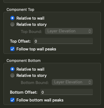
-
Just downloaded the new service pack and all fixed - thanks very much! (image from solibri)

- 7 replies
-
- 4
-
-
- landscape area
- ifc export
- (and 2 more)