digitalcarbon Posted November 2, 2013 Share Posted November 2, 2013 any idea on how to model this? to see it in google earth search parque marinha do Brasil Quote Link to comment
Benson Shaw Posted November 2, 2013 Share Posted November 2, 2013 Draw an upside down omega shape for section. eg 2d poly, then convert to NURBS. Draw the ground plane path, say at bottom of trough. eg 2d poly Dupe along path, tangent. eg 10 meter increment, or 20 of them along the path. Select the whole group in side view and rotate to give desired slope/fall (or adjust the z of the path points to desired config. Select the path and the section and Dupe Along Path, Tangent Adjust individual ribs z or scale or shape to give variation. Loft Surface by clicking each section in turn. Easy! -B In and loft among them. Bowl at each end models separately, but with ribs or contours Quote Link to comment
Benson Shaw Posted November 2, 2013 Share Posted November 2, 2013 (edited) Here are some images and maybe the file. I'm on a slow connection right now. Added an image of trough with a few of the ribs rescaled in z to make an undulating surface at bottom. But did not upload revised vwx. -B Edited November 2, 2013 by Benson Shaw Quote Link to comment
digitalcarbon Posted November 4, 2013 Author Share Posted November 4, 2013 ok thanks did you see how it gets wider and then ends into a bowl? Quote Link to comment
digitalcarbon Posted November 4, 2013 Author Share Posted November 4, 2013 ok i see the mention of a bowl as to wider the faster you get in these things the wider one needs to make it so the bottoms are wider Quote Link to comment
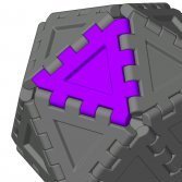
Benson Shaw Posted November 4, 2013 Share Posted November 4, 2013 (edited) Right, You could generate the various section shapes from some data and place them on the path. eg at station 100+10 offset 50.255 you need to accommodate speed of 35, therefore you need width of 25 and depth of 10 and Drop in slope of 85? and bottom fillet radius of 3 etc, etc). But I doubt much of that data exists I assume you need to generate a test shape based on initial site constraints, pull the sections, modify to accommodate expected speeds, turn radii, etc as known from other skate facilities or your own experience and engineering parameters. The DAP units can be initial guides. Modify them as needed with scale, reshape, reposition, or other tools. Another method is to draw contours. Example drawn with only centerline (bottom of trough) and each upper edge (no coping or perimeter walkway, no intermediate contours). This is oversimplified - Could have more contours to control section shape, could start with more 2d normals, no need to center normals on CL. Blue 3d has no fall, bottom z= 0, edges z=10. Pink 3d, CL has about twice the fall of the edges. Or actually build a site model (makes my brain hurt). HTH -B Edited November 4, 2013 by Benson Shaw Quote Link to comment
digitalcarbon Posted November 4, 2013 Author Share Posted November 4, 2013 wow! how do you get so good with this stuff? thanks for all the help. did you get to see the one in Brazil? Quote Link to comment
Kevin McAllister Posted November 4, 2013 Share Posted November 4, 2013 Benson, You have an awesome amount of control over NURBS in VW! These shapes always tend to fail when I attempt them, even using similar methods. Well done. Kevin Quote Link to comment
Vectorworks, Inc Employee PVA - Admin Posted November 4, 2013 Vectorworks, Inc Employee Share Posted November 4, 2013 Benson, excellent explanation. If you don't mind, I may steal your method for use in a future 101 or VTT. Quote Link to comment
Benson Shaw Posted November 5, 2013 Share Posted November 5, 2013 Thanks for the strokes, folks. Use these ideas as needed. I'm mad about NURBS, I guess, so use them lots. Just don't ask me how to make a door in a wall display as open in Top/Plan. DM- I did look at the Brazil parque marinha do Brasil - both the Earth view and some of the online photos. I find it wonderful. Would that skate parks and other urban amenities in my neighborhood were as well conceived! Kevin - I find that duplicating a shape (eg the omegas or the center line) and reshaping the iterations makes the final loft work better than creating new shapes for each section or contour. That controls the vertex count, among other things. -B Quote Link to comment


Recommended Posts
Join the conversation
You can post now and register later. If you have an account, sign in now to post with your account.
Note: Your post will require moderator approval before it will be visible.