Search the Community
Showing results for tags 'wall tool'.
Found 9 results
-
 The more I model in Vectorworks and the more I coordinate with structural engineers the more I find that I want to model these parts of my model separately: Elements external to structure Structure Elements internal to structure The reasons being: When we model complex walls/slabs/roof objects the automatic connections between these objects are just too opaque and prone to error. Separating them makes it much easier to make and maintain constructionally correct connections. It also becomes easier to coordinate with the structural engineer. For instance it becomes very straightforward to isolate and export one's own structural model. You can model in this way now but it's messy because you have to manually manage the position of multiple walls/roofs/slabs instead of one. One way to solve this might be some kind of parallel wall, roof and slab connection, so that we can "magnetically" snap walls together in parallel, roof faces together in parallel, and maybe slabs (but to a lesser extent). These parallel connections would work across layers. And—unlike Grouped objects—we'd be able to make standard joins with other wall/roof/slab objects, independently for each object connected in parallel. When you move objects connected in parallel they all move together but their connections with other objects are maintained. When you insert an object (e.g. window, roof light) they're inserted through all objects at once. VE-102325
 -
With walls I am sure there are many users who would want to see more realistic Wall Coverings instead of the current Texturing which has been around seemingly for ever. This image shows what can be done with an existing tool - Create Planar Display - to produce an accurate siding weather board. The second image shows metal siding/ roofing material. How difficult is it then to extend this and produce realistic wall coverings.


-
I am wondering if there a particular method for using the wall tool in order to achieve seamless joins? Am I alone in finding the execution of seamless T junctions and right angles frustratingly tricky after editing or moving a wall configuration. It is sometimes simpler to delete the whole wall or the network of partition junctions and start again in order to achieve a seamless connection at the point where the walls intersect. This can be an onerous task sometimes taking several attempts before resulting in clean joins. When all attempts fail, I resort to using the 2D polygon tool to clean up. Perhaps I am not fully understanding the left and right control modes when using this tool, and am doing something counter-intuitive Is there a keyboard shortcut for changing between these modes? Any help, or tips, would be much appreciated, thanks.
-
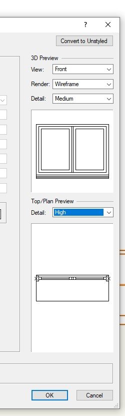
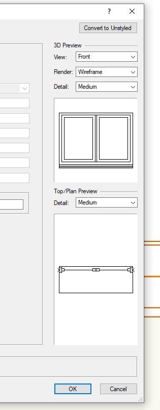
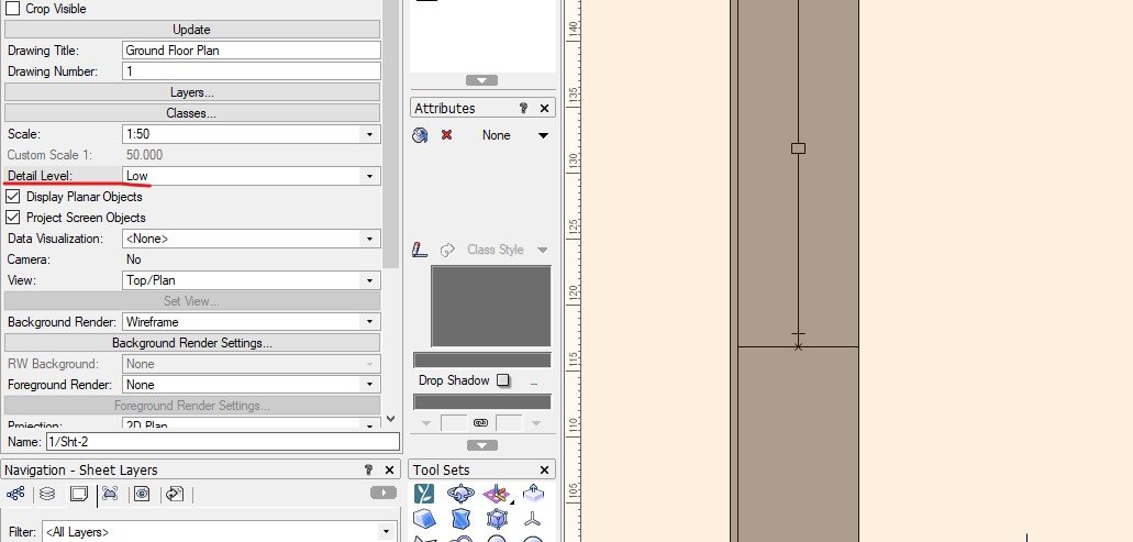
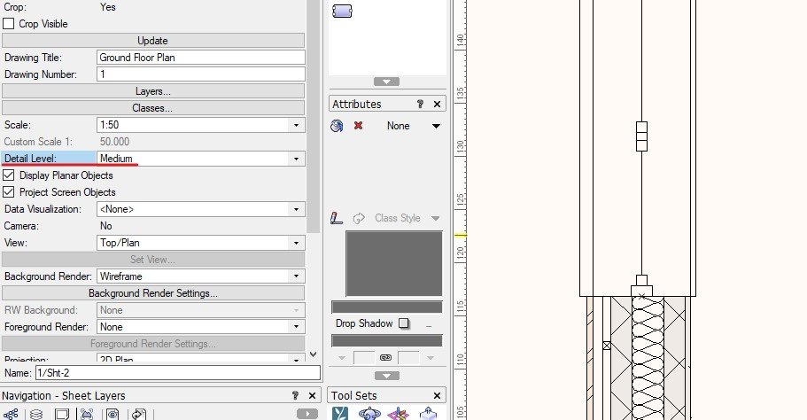
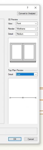
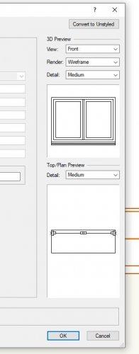
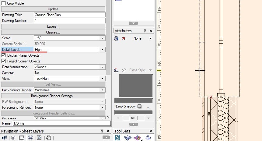
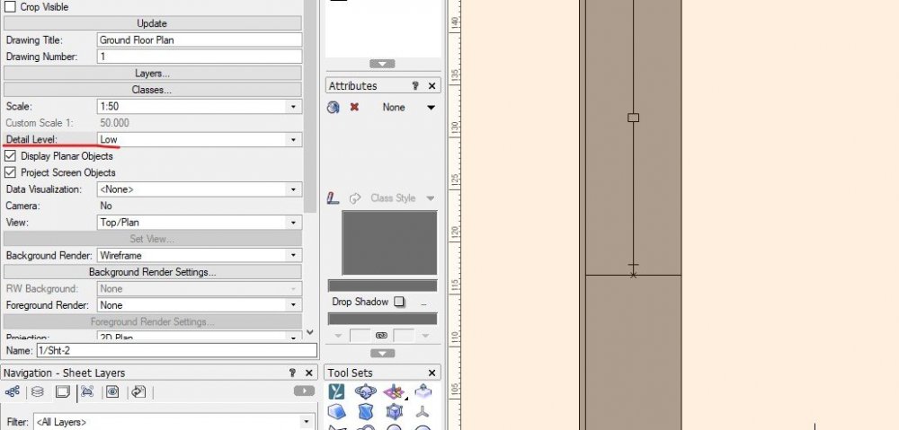
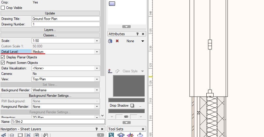
Hi all, I cannot find the way to edit the viewing Level Details (if you can call it like that) for certain symbols, like Doors, windows and wall styles, i know when you're creating a symbol you can choose what to see in LOW, MEDIUM and HIGH detail that you can then setup in the viewport but on 2020 i cannot find that option for windows doors and walls, (on how to edit the detail level not how to choose it in the viewport as you can change it easily on the OIP) I've attached the window tool example of what i'm addressing if i wasn't clear on the question. Window Tool preview you can see the differences and for the viewport example where i choose the detail level i want to show, the wall goes from a complete gray to detailed version, i wanted to change this let's say the low and medium settings for the wall i wanted it to be Gray and in the High setting i wanted to see the detailed version of the wall for example, how can you change this either for wall, door and window tool??

-
Two wall tool requests. Walls from Polylines: I would like to have custom Walls that can be generated from a closed poly-line (as opposed to the wall tool that uses two-point "lines") We work with concrete on a lot of our projects and the workaround to make varying thickness or shaped walls is very cumbersome. I can see a simple wall tool edit that can generate shape from a poly-line OR a wall component that can have a "Taper/Shaped/Custom Outline" in the dialogue similar to tapered slab components to generate the geometry. "Free-Standing" Wall Components Free-standing wall components that can "glue-on" to walls. For example, if one room of a project has wood slats on furring strips, I'd have to make a wall type for each wall (exterior, interior, bathroom plumbing walls, that ALSO have furring strips on the side face that room). But I'd rather create a wall that has wood slats and furring strips only and apply it only to the walls facing that room. I would do this with tile, interior finishes, etc as well. Basically, re-orient how VW thinks of wall assemblies to align to how real-world assemblies are realized.
-
Howdy, Working on a home design and file seems to have gotten corrupted. My wall tools do not work in many aspects. I cannot select walls that are drawn. I can draw a wall but then I cannot edit. Have I accidentally changed some setting or is this file damaged? I have quite a bit of work in this file! Thanks Jack
-
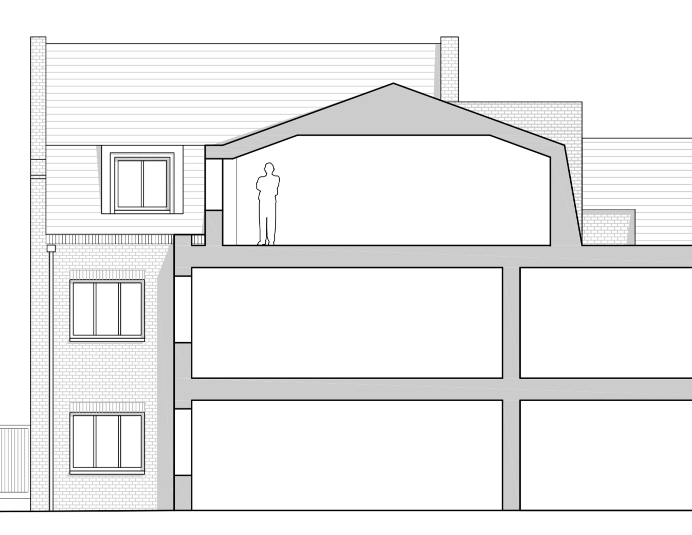
How would you approach the modelling of this mansard roof and walls? They're construction drawings, so need to show correctly detailed in plan and section. I was wondering about drawing the walls in plan view with no z-height, and then modelling the mansard roof and walls with the roof tool... and may slicing through it in plan somehow to show extent?

-
Hello, I have created a wall using the wall tool and want to render it using a rendtrworks texture that I have created. Only the top, right and left sides of the wall are accepting the texture, not the front. In the object info pallet, the part selected is overall and the texture is selected. The wall has a solid fill. I have tried giving it no fill, have adjusted the modes and parts to accept the texture. I am not sure what to do to make the front/visible part of the wall accept the texture. I have attached a screen shot to show what I am experiencing. Any and all help is appreciated. Thank you!
-
I'm trying to quickly add wall colours to walls drawn using the wall tool. Trouble is, the colour seems to apply to the wall ledges, but not the faces. There must be something obvious I'm missing, but I can't see what it is...any ideas?