Jake DeGroot
-
Posts
411 -
Joined
3 Followers
.thumb.jpeg.48a6fdc44e48c98b8e1b507e86e57e95.jpeg)


-

Fixture 2D Components - 3D vs Schematic Views
Jake DeGroot replied to spettitt's topic in Entertainment
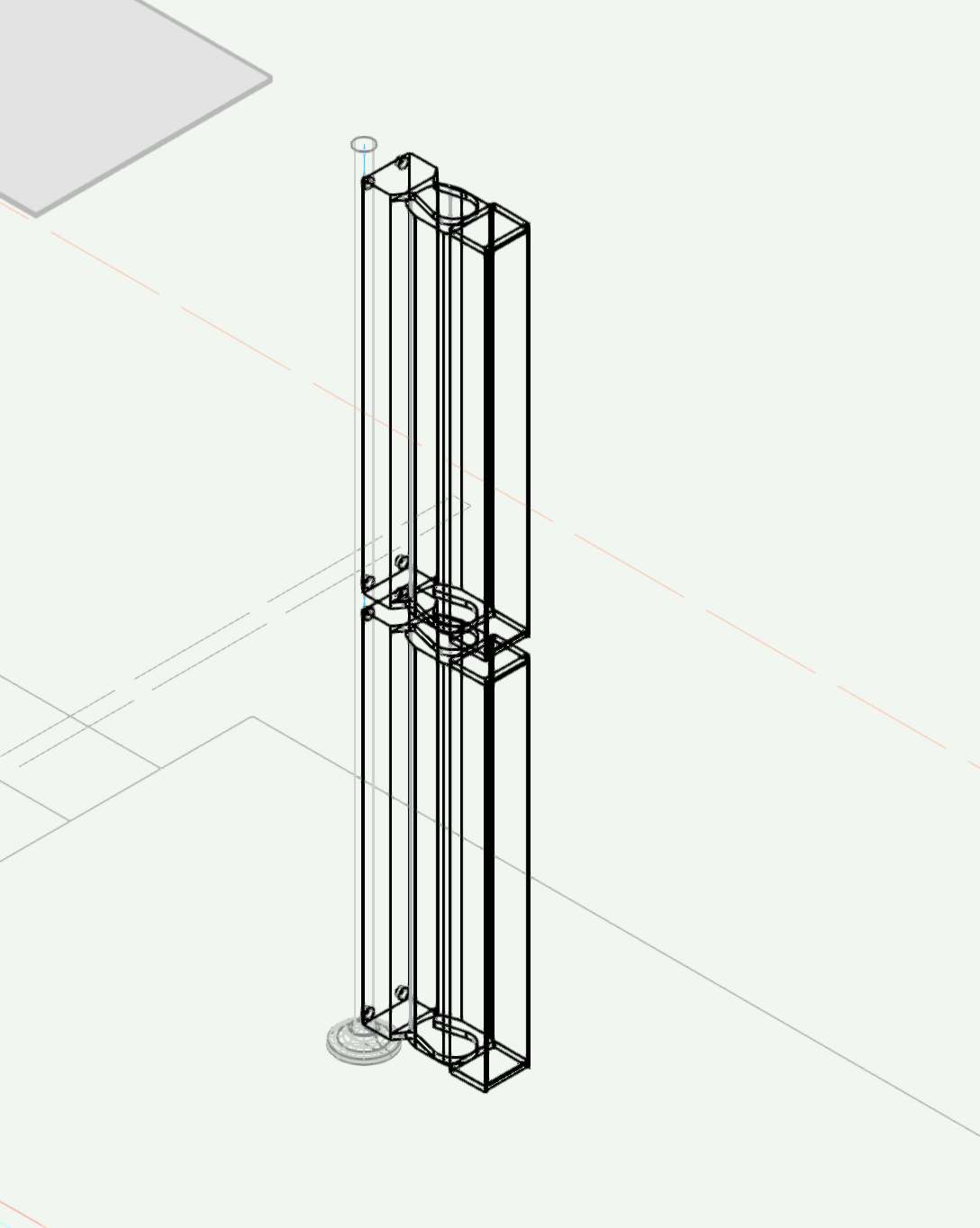
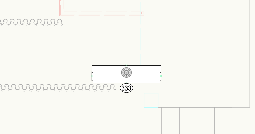
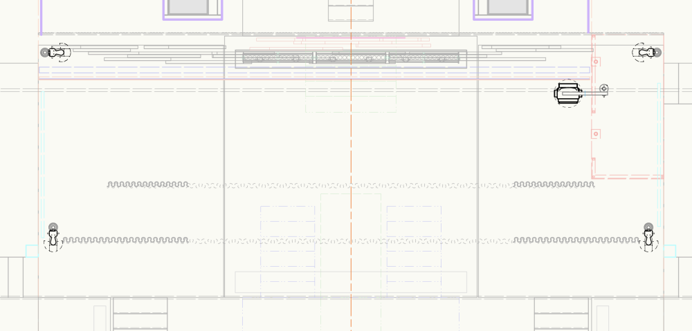
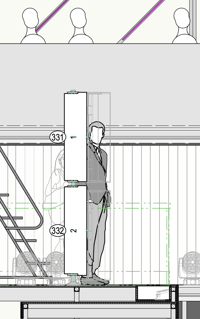
Thanks! I recently Zoomed with @markdd about this, as I believe you maybe did too. He is so generous with his time! I share most of your goals and challenges, but landed on a slightly different solution. For my booms full of vertical striplights, I drew them on their side as shown in Mark's webinar. Then, when I flip the positions up with a 90° roll angle, the lights rotate naturally. And when I make a SV of the position, and select Top, it shows everything as I would hope. 3D: Schematic View (dropped on top of a 2D section drawing of scenery): The big down-side of this is that in normal Top/Plan view, the position looks silly and is unusable. What I really want is for that Top/Plan to show me a "footprint" view of the lights, so I'd see their Right or Left 2D Component. But there is currently no way to do this. So what I'm doing instead is keeping the 3D geometry on a separate "Lights - Vertical" design layer which I keep invisible in most cases and only turn it on when I specifically need to work with these positions. Then, I make a Horizontal Section view on a design layer. I give it no crop and have it only show stuff from that "Lights - Vertical" design layer. This gives me one big full-stage viewport containing the proper 2D components (or hidden line renders) of my fixtures in the proper orientations. I keep this viewport visible in both my normal design layer work and in my sheet layer viewports. It's working pretty well. I have found one bug that design layer section viewports or not showing 2D fills. I wish the footprints were filled in gray, but they're not. Alas. Hopefully VW will fix this soon. And I do wish this whole thing could be made so much easier and more intuitive if VW would adopt your suggested change where we could select a light in a Schematic View and manually change which 2D component or 2D view we want to see it in. In fact, I would even suggest taking this one step further and making it possible for any lighting device anywhere on my drawing, not just in a Schematic View! Give us a toggle in the OIP of a lighting device to let us select which 2D component we want spotlight to use for Top/Plan! Then, in my example, I could just change the Top/Plan component to Right and I would see my footprints the way I want to. Basically, we could come at it from either side and we could make the Top/Plan symbols of our lights show the geometry that makes sense based on the light being rotated in 3D.
-
Fixture 2D Components - 3D vs Schematic Views
Jake DeGroot replied to spettitt's topic in Entertainment
I came here today because I'm having almost the exact same issue. Trying to use Schematic views for the first time with vertical booms and having no luck. Thank you for documenting it so well! I was dreading having to do that myself. Am I correctly understanding that you found no real solution and had to give up on Schematic Views? How are you using viewports to do this? Are you able to get label legend labels to show in the Viewport? -
Vision 2019 SP3 MVR Improvements
Jake DeGroot replied to bbudzon's topic in Vision and Previsualization
What @Cory Pattak says here is certainly, unarguably, true. It is also the exact same thing that @bbudzon is saying in the post right above that: I think we're in vigorous agreement here. The challenge is not convincing the folks at VWX that the Vision UI and Vision backend should be decoupled; the problem is, as always, convincing them to prioritize the time and energy towards what amounts to a major project of actually doing that work. One quick question on this, @bbudzon - I understand that the values in the vision properties window are directly used by the backend so adding strings to them is a no-go. Are the keys also directly used? Could you more easily change "X" to be "X (inches)"? Or is that the same problem? -
Vision 2019 SP3 MVR Improvements
Jake DeGroot replied to bbudzon's topic in Vision and Previsualization
Thanks for this, @bbudzon. Trying it out now. A few questions: In the Export MVR dialog in VW: I see the list of object types to export with check marks but I don't see a way to clear check marks and prevent some objects from being exported. I don't want my Title Block Borders to export to Vision. I have tried single-clicking, double-clicking, space bar, right-clicking. Nothing works. When I change the "Settings" Radio Button, from "All Objects in the Drawing" to "Visible Objects", I would expect the object counts to change in the Object Types pane. They do not When I change the "Settings" Radio Button, from "All Objects in the Drawing" to "Selected Objects", The object counts do change, but they do *not* reflect what I actually have selected (currently nothing). I just tried exporting an MVR of visible objects and it included everything in my scene. When I did select some objects in the scene, I was able to export just those. When the fixtures arrive in Vision, they are not named according to their channel as they are via ESC. The "Name" of the Vision node now seems to be the VW "Unit Number", and the VW "Channel Number" is nowhere to be found, despite my Mappings in VW's Spotlight Preferences being corrent. This maked it impossible to identify my fixtures in the Vision Scene Graph. Things only look right when I tell Vision the unit in my MVR is millimeters, even though the unit in the VWX that was the source of the MVR is inches. Why? But the geometry does render nicer. And splitting up the objects and tracking them by UID is a wonderful improvement! -
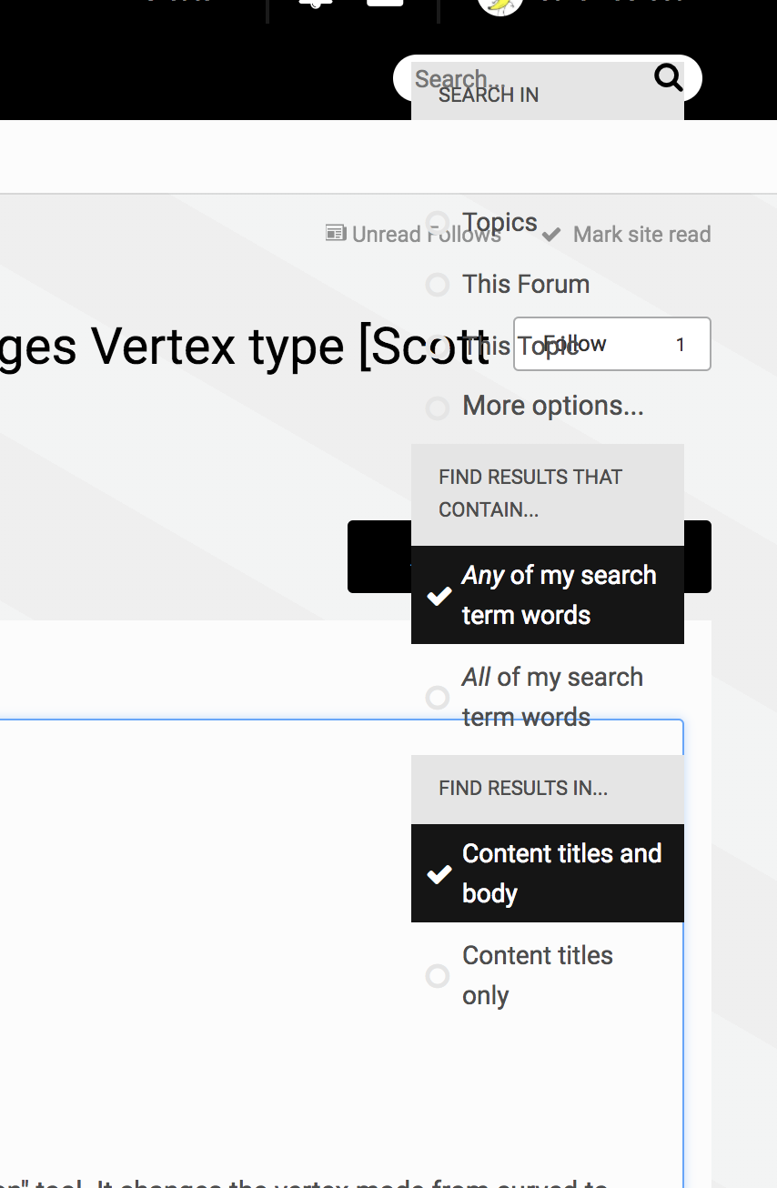
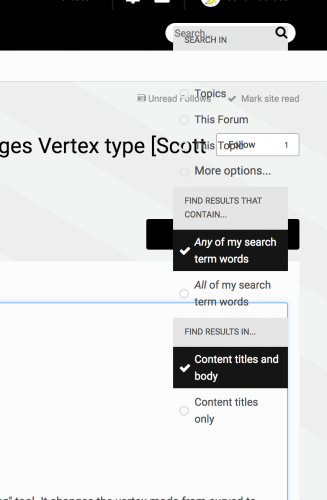
There seems to be an issues with the CSS of the "search in" drop-down on the forums today.
-
What happened to forum user reputation buttons on posts?
Jake DeGroot posted a question in Forum Feedback
We used to have buttons on all posts to plus or minus user reputation for the author, right? I am not seeing those any more. Did you remove them on purpose? @JimW -
Jake DeGroot changed their profile photo
-
Thanks, Rick. But yes. I really do mean what I said: various symbols all referencing the same database record. I realize that in most cases, one symbols equals one unique record, but I'm trying to see if there's any way to cheat. The scenario is for lineset schedules/labeling. The idea is that I have many symbols that describe the same lineset. There is the actual lineset symbol in the hanging chart, there is a label and trim in the section, and there are two labels with trims in the groundplan view. I want to have all 4 of these symbols linked in some what so I can change the trim on the section label (or better yet, have a script I've written change the trim based on the actual Y position of the symbol) and have that new trim reflected in the plan and the hanging chart. This may not be natively possible, and the best option might be copying and pasting in worksheets, but that is still a step I wish I could automate. In terms of the bulk editing you're talking about, I do most of my bulk editing in LW using data exchange to sync back to VWX. In terms of what you said about it being difficult to find and sort symbols in the drawing, I would recommend looking into Spotlight's Find and Modify feature, but also looking at Josh Benghiat's Savvy Select Similar Instrument (http://www.benghiatlighting.com/software/products/ssi1),
-
Is there any way to have multiple instances of various symbols all referencing the same database record? Like they'd each have the same record format attached and when you change the data in one, all others update?
-
Never mind! Answered my own question: ForEachObject(MyProc,(R IN [MyRec]) AND INSYMBOL); Thanks again!
-
This has been a super useful thread. Thanks, guys! I am adapting Pat's script from https://techboard.vectorworks.net/ubbthreads.php?ubb=showflat&Number=212682#Post212682 and it's working great as long as the symbols are loose on the drawing. How can I modify it so it would work even if the symbols are nested within another symbol?
-
Ever since upgrading to VW2015 on my Mac running 10.10.1, I am experiencing a very annoying bug. Whenever I have a Vectorworks window open in the background with another app in focus, then I activate Vectorworks by clicking in the drawing window using my middle mouse button, Vectorworks essentially gets "stuck" in pan mode. Vectorworks doesn't technically take focus on my mac, but I can pan the drawing. In fact, the cursor remains a selection arrow, but moving the mouse around pans the drawing. If I left click in the window to actually activate Vectorworks, my cursor changes back to the pan hand, but all the toolbar menus and commands are grayed out and unavailable including save and close window. The "Vectorworks" window is the only one that remain accessible and the only way I have found to actually continue working is to quit Vectorworks, tell it to save when it prompts me, and restart the app. Ugh!
-
What is going on with Retina Display support? In this Knowledgebase article it says VW2013 just barely missed out on Retina display support and "Future versions of Vectorworks will make great use of the high resolution Retina displays." But now here we are with 2014 released and looking terrible on the brand new MacBook Pros with Retina Display. What gives? When can we expect support?
-
In my sheet layer viewports, cropped design layer viewports are not showing up. As soon as I add a crop to my 3D referenced Design Layer Viewports, they disappear from sheet layer viewports. Why? Any way around this?
-
Thanks for the reply, Kevin. Bug submitted for second one. Could I possible then turn #2 into a feature request? It was an incredibly useful part of my workflow and have spent a huge amount of time making custom legends for different lights in different orientations and assigning them all to be the default per symbol. Why would this not be the intended behavior when it works so brilliantly? Since the default Light Info Record has no "Use Legend" field, who does it hurt by keeping the feature as it was? For most users, it will remain as-is, but for power users who want to make custom Info Records, it saves hours and hours. Please bring it back!
-
I have a drawing with a whole bunch of referenced resources. I want to reference more resources from the same source file. I navigate to the source file in the resource browse, right-click on the symbols I want to bring in, and click reference. It asks me where to put the symbols and I keep the "Preserve Folder Hierarchy" option checked. So far so good. But, when I look in my destination file, the new references in there in the proper folder, but in addition to that, Vectorworks pulled any embedded symbols into that folder too. So, for example, I have a C-Clamp symbol referenced in an Iron folder. Then I reference in a new Source Four Section Symbol. It goes in the Source Fours folder, but when i do that reference, since the C-Clamp symbol is used within the Source Four Section symbol, it pulls the C-Clamp into the same Source Fours folder. Thus, all my organization gets all messed up and I have to hunt and peck trying to find symbols that aren't where I put them. Grrr.