


Ross McLee
-
Posts
120 -
Joined
-
Last visited
Content Type
Profiles
Forums
Events
Articles
Marionette
Store
Everything posted by Ross McLee
-
Hi, One for @Conrad Pand Co.... Would it be possible to add a URL field to the Device symbol definition (and perhaps others) which you can populate with a link to the manufacturer's data sheet or website perhaps?... Might be handy when creating reports to link to the website for further information, installation manuals etc.. Cheers, R
-
Not at all. Appreciate the efforts you and the team go to. R
-
Absolutely.. Creating Equipment Items based on selected devices only was a first choice yes!!! 🙂 I could then block and move them as Equipment items ! as they were 'delivered' to the Rack Elevation layer one truck load at a time ... I agree the workflow isn't always an easy one.. perhaps as the 'removal firm deliver' they take the opportunity to se which boxes have room labels on them and drop the boxes off in sequence as they do now.. but add a bit of space between anything where the boxes have a label on them already ... Dare I suggest 'grouped' (But I have discovered grouping is often frowned upon 🙂). I was just asking about adding data records now as a workaround until the 'ultimate solution' is available. Thanks as always, R
-
Hi, One for @Conrad P I think.... I would like to be able to pre-assign the room/location in which my devices will be located without having to first create the rooms in the Rack Elevation Layout layer, running update rack equipment, and then placing each linked Equipment Item into their specific rooms. Reason being - I have drawn the schematic as individual room systems and positioned them on the drawing so that they are grouped in rooms. The rooms contain lots of similar items of equipment so telling which one is which, and then dragging each one into a room is very time consuming. I can't enter the room names to the Devices via the OIP, so I was wondering to speed things up. Could I attach a data record to Device and use that to allocate my own room/location data... and then some how transefer my data record information into an Equipment Item (linking them by device name as normal). So that I can select Equipment Items where MyRoomName = X and select them all and drag them into a room. Does that make sense?... or is there a better way of doing this I am missing! (Creating separate layers for different rooms (and updating rack layout for current layer seemed excessive and would be painful to change the circuits between them) Thanks, R
-
Team workspaces - save to workgroup folder
Ross McLee replied to Ross McLee's question in Wishlist - Feature and Content Requests
"....Like a box of chocolates"..... -
Text editor - CTRL/CMD + ENTER to complete
Ross McLee replied to Ross McLee's question in Wishlist - Feature and Content Requests
Thanks for the prompt reply @markdd. Just tried it on Windows. Nope. ALT+, CTRL+ and just ENTER on its own insert a line break. ESC is the way to 'enter'. I know in Excel you can press ALT+ Enter to add new lines in a cell without completing the input. -
Team workspaces - save to workgroup folder
Ross McLee posted a question in Wishlist - Feature and Content Requests
Trying to manage a team (in my case quite small) and keeping our tools and commands in the most efficient locations is a bit of a challenge. As I understand it, when saving a workspace it is stored to the user folders. If you want to share that workspace with the team (so they can benefit from your development) you need to copy the user folder contents to the workgroup folders. I have done this. However If I want to edit the workspace further it is saved back to my user folder (is that correct). It would be good to allow users (possibly just admins?) to edit the team workspaces directly (just as you would a standard template) so that everyone benifits and works in a similar way. It's not for everyone, so they are still entitled to use their own workspaces, but... Cheers, R -
Text editor - CTRL/CMD + ENTER to complete
Ross McLee posted a question in Wishlist - Feature and Content Requests
Hi, A simple feature request please (from a former AutoCAD user). I believe there is lots in the pipeline for text editor functionality. One niggle I struggle with is pressing ESC to complete entering your text. It is just not sensible. Escape should mean cancel what I was doing and go back a step. https://app-help.vectorworks.net/2018/eng/VW2018_Guide/Text/Creating_a_Line_of_Text.htm#XREF_79678_Creating_a_Line_of ACAD uses CRTL+Enter text, but it can also be used elsewhere when you want to execute a command/dialogue box after entering the text string value. Email applications use Ctrl+Enter as SEND (e.g. Outlook). Thanks, Ross Edit: LOL ... (AND PRESSING CTRL+ENTER on this forum page, submits my question too!!!) -
Assign object to a layer checked out by another user
Ross McLee replied to Ross McLee's topic in General Discussion
Thanks @Christiaan - I thought as much! I guess, a temporary design layer could be used in this approach.. have my colleague save, commit and release the his 'live' layer, then I would checkout the layer along with my temp layer, 'transfer' from my temp layer and then save, commit, release again. Cheers, R -
Assign object to a layer checked out by another user
Ross McLee posted a topic in General Discussion
Hi All, Is it possible to reassign an object from a layer I have checked out to a layer my colleague has checked out? I realise this might mean I can no longer edit it, but would mean I can add content to their layer in parallel to what they might be doing on that layer. Perhaps we are working on different ends of a building, for example I do the east end, my colleague does the west end. They work 'live' on the layer' I work 'off-line and sync'. We will both need to save/commit/refresh etc. Thanks, R -
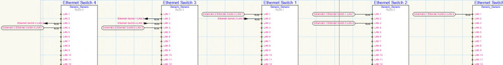
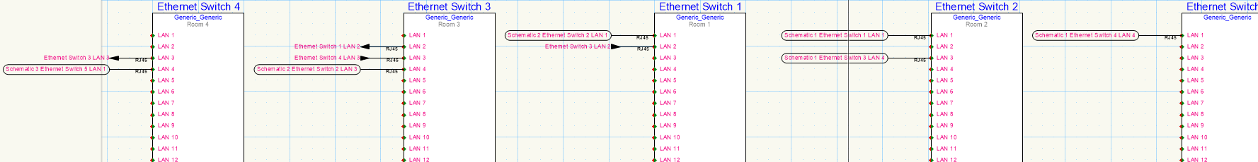
Hi again, Finding my way around ConnectCAD a little more comfortably. Q: When connecting two sockets using the arrow connector type OR when connecting two sockets across two layers. Is it possible to customise what the circuit label displays? It would be particularly handy for example if the label said the destination room or rack. When a circuit crosses between two layers, displaying the layer names is not particularly helpful (especially if they are simply called schematic 1 and schematic 2). I suppose I could change the devices to be more descriptive of the location, but would prefer to automate it through the location: room or even rack properties. Example of all the variants I have come across so far, attached. Note: Show all layers is on, so you can see all three layers clearly. Thanks as always, R
-
- 1
-

-
- connectcad
- circuit
- (and 2 more)
-
@MTRobin - sounds like you are on a similar journey to me - good luck! @Pat StanfordWhen it comes to inserting 'things' and manipulating them - how does the script know where to get the thing (in this case a symbol) from? Does it need to already be a resource within the file, or will VW search for the symbol in the resource library, which then begs the question what if it doesn't exist, or if there are duplicates (but I will skip that for now). R
-
Custom selection (save/recent options)
Ross McLee replied to Ross McLee's question in Wishlist - Feature and Content Requests
@Pat Stanford, I realise this is really easy stuff for you, but I appreciate the taime you have taken out to help me. I can read the script and understand how it works, but wouldn't have known where to start. I might venture further and try modifying it a bit once I am more familiar with the whole scripting thing. But this works just as I wanted. Thanks again, R -
Really loving this very handy tool. Could you increase the size of the input boxes (e.g. prefix) so I can see larger strings of text? This tool comes in so handy to do smart text find/replace with numbering the prefix could be 10-30 characters long! Additional thought - would it be possible to see a preview, of, say the first 5 items, before committing the update (of course you can undo, but... a quick preview would be good) Thanks, R
-
Custom selection (save/recent options)
Ross McLee replied to Ross McLee's question in Wishlist - Feature and Content Requests
It is a single line at the moment: SelectObj((INSYMBOL & INVIEWPORT & (PON='Device') & ('Device'.'name'='<USER INPUT HERE>'))); I am possibly getting out of my newbie comfort zone here 😉 R -
Custom selection (save/recent options)
Ross McLee replied to Ross McLee's question in Wishlist - Feature and Content Requests
@Pat Stanford, My first delve into Vectorscripts and this worked pretty well. Thank you. I have made a few scripts already now 🙂 I am going to regret asking but... Is there a 'simple' way of prompting the user (me) to select/enter just one of the search criteria via an input pop-up?... I am trying to select all ConnectCAD devices who's name is X, but X changes each time, and scrolling through the parameter values in the custom select tool is very time consuming to find the .device.name field. The script would be a shortcut to that I guess. Thanks as always, R -
Hi @Conrad Preen, I understand the workflow above - could you also explain what the NAME property is about in the Layout Room object. How does it differ from ID. Obviously ID is used to link devices to the room via the Equipment Item objects, but I couldn't find a purpose for the name property. Thanks as always, R
_LI.thumb.jpg.6517901311debfec3391ed2f2d475d25.jpg)
-
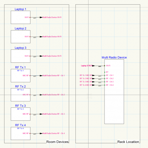
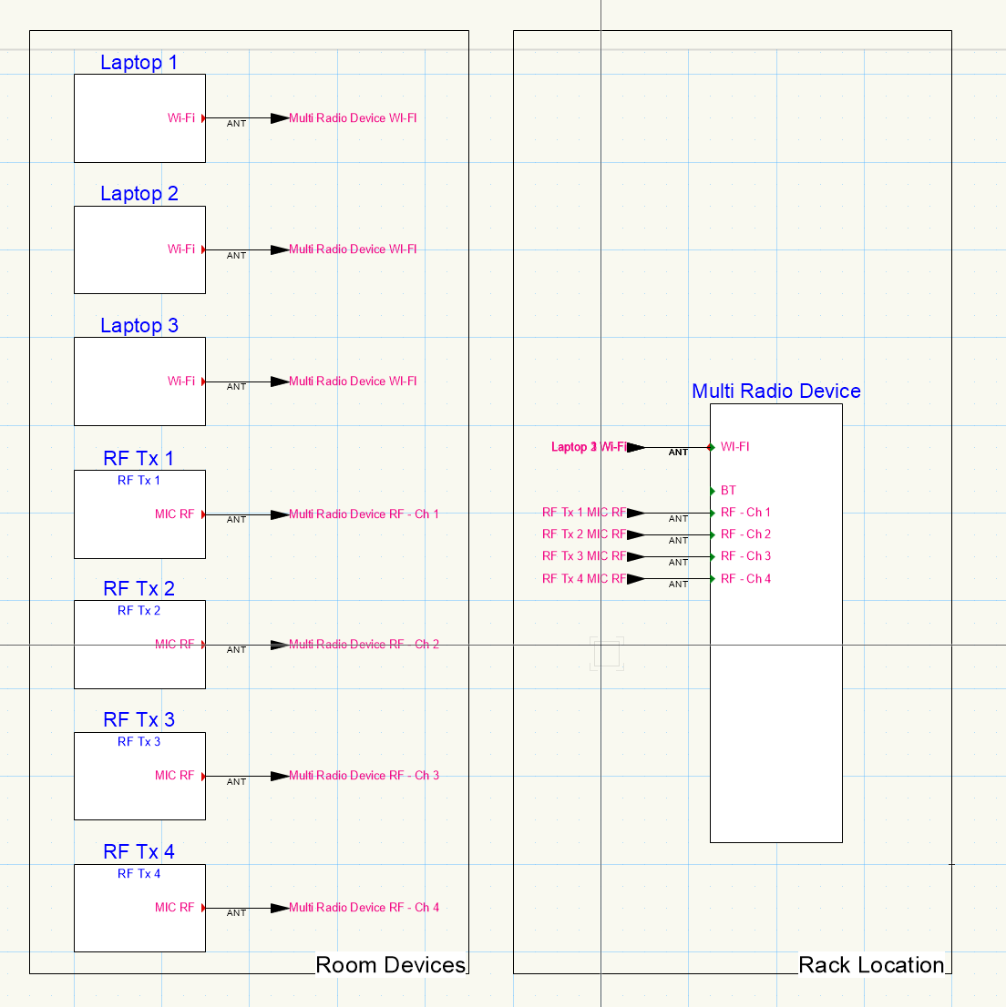
So I'm thinking this is the way to go (pretty much as you suggest too). This way the locations of the devices can be made clear. Just not sure how I can stagger the multiple arrow connectors that connect to the single [wi-fi] socket so I can read them correctly. Any ideas?
-
This looks similar to what I have Eliot, thank you. I like the header information - I might just grab that!) I note you are not showing the transmitters though. I was just thinking about other wireless products that could come into play like Wi-Fi, Bluetooth, etc in AV projects (e.g. lecture theatres). Beinagable to demonstrate which Tx/Rx devices are paired up would good too. Thanks again for your input, really helpful. R
- 5 replies
-
- 1
-
-
- connectcad
- radio microphones
- (and 1 more)
-
Custom selection (save/recent options)
Ross McLee posted a question in Wishlist - Feature and Content Requests
Love the custom selection tool. It would be greatly improved if: It kept your last used criteria - sometimes you need to repeat the process to achieve what you want to do Allow to save the criteria for future use (a bit like select similar tool) BONUS option - When selecting criterial the lists are filtered. E.g. I am looking for devices in ConnectCAD, which have 0 power values, so i filter on DEVICES but still need to trawl through hundreds of properties for doors, windows, walls etc just to find the properties of Devices Thanks, R -
Hi, New to ConnectCAD - I was wondering what the best practices are for making RF connections in ConnectCAD schematics. Showing them accurately/correctly in the schematic and perhaps scheduling channel assignments. I am looking at using arrow connector types. With diversity I have A and B antenna but only showing connections to A for the moment. Just wondering what people recommend and anything to look out for. Help always appreciated. Ross
-
Feedback. Minor issue doesn't impact use. But I noticed when copying a device (ctrl+mouse click and drag) that the indicative outline of the device as I moved the mouse, included the arrow connectors which the source device had connected. I panicked the first time .. but on releasing the mouse button the device copied as it should, the outline just confused me for a moment I thought had selected everything - not just the device on its own). I guess this is mimicking move behaviour , not copy. In the attached screen grab I couldn't keep the CTRL key depressed and take a snap shot (so you can't see the + sign mouse pointer) R
.thumb.png.ecc1f3c88c98192e5b0f1ed598302d56.png)
-
Hi, Is there/could there be a way to prompt users to confirm changes they have made to a symbol when they close the symbol editor, perhaps offering the option to save as new symbol. Coming from AutoCAD when editing a block you have the option to save, save as new block and dismiss changes. This would be a quick way of modifying a series of symbols which are similar but only need a small modification each time, instead of creating multiple copies in resource manager and editing each one. I have tried editing the 3D components of a symbol recently and really messed it up and couldn't work out how to exit the editor without saving, and I didn't have enough undo's !!! For the more advanced users this could be an option that could be turned off through user preferences. Cheers, Ross
-
cloud service import/export functionality
Ross McLee replied to grant_PD's question in Wishlist - Feature and Content Requests
Agree with this one - absolutely. Considering there are lots of ('other') on-line viewers that do this for lots of file types having the ability to use on-line processing power to import big files and not make my workstation slug it out for hours, while I get on with the real work. This functionality would be awesome.
_LI.jpg.bb55644f4c62a413d04e1f1955114a54.jpg)
.png.c9044077cc7af8712b47326d77907810.png)