Tom W.
-
Posts
5,067 -
Joined
-
Last visited
Content Type
Profiles
Forums
Events
Articles
Marionette
Store
Everything posted by Tom W.
-

Putting Hanging Position Labels into a Circle/Square/Hexagon
Tom W. replied to Darin K's topic in Entertainment
Persevere they are essential. Post a file if you want someone to help set it up -
These dims determine the size of the Image Prop. So most of the time you'd set them to the 'real' size of the object, but in the case of a Plant I'm not sure it makes an awful lot of difference since you set the size parametrically afterwards...
-
I think it is a one-off object that was converted into a hybrid symbol solely in order to give it a Top/Plan representation. Hybrid symbol was chosen over Auto Hybrid to have more control over the 2D representation. I guess the advantage of an auto hybrid is that if you do find you need to edit the size of the object you just need to edit the 3D component + the 2D will follow automatically whereas with a hybrid symbol you need to edit the 3D + 2D components separately. However in the grand scheme of things we're still only talking a few seconds...
-
Not centre on import: the 'Centre Drawing on Internal Origin' command.
-
The workflow is covered in this video: https://university.vectorworks.net/mod/page/view.php?id=1349
-
Landmark - Plant Schedule displaying image of plant
Tom W. replied to J.Aspect's topic in Marionette
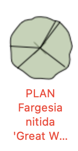
When I tried it yesterday I found I could add images to some of the plant styles but not others. For some reason those with the coloured circle graphics I couldn't get the image to display in the worksheet e.g. yet those with the 'normal' graphics I could e.g. Couldn't understand why so left it hoping someone else would explain...
-
The parameters you want to be the same for all instances of the style should be set to By Style (bent arrow icon). The parameters you want to be able to edit on an instance by instance basis should be set to By Instance (pair of sliders icon). This is in the style settings. Then in the settings for instances of the window you will see the By style parameters are greyed out + can't be edited + those which are By instance can be edited.
-
I'm not sure this method will be suitable because in the case of a hybrid symbol it will result in one of the components being lost as you can only Command-K either the Top or the 3D component. @Darin K I would just edit the symbol definition: youve said it's only very simple geometry so it should only take a couple of secs.
-
I don't centre my site/geometry on the Internal Origin. I have a georeferenced template file where the IO is central to the geographical area I work in. Because of the nature of where I work, all of my projects happen to fall within a 5km radius of the Internal Origin so I don't need to do anything: I can just draw wherever I want based on the real world location of where the project happens to be. But if I had a project outside that 5km boundary I would just re-centre the drawing on the Internal Origin which would in effect move the geometry AND the User Origin together, relative to the location of the Internal Origin. So my geometry would have the same relationship to the User Origin - would still have the correct coordinates - all I'd have done is moved it + the rulers relative to the IO. I believe best practise in BIM - when coordinating with others - is to agree a common Internal Origin point - like you say, a nice round number - as a belts + braces way of ensuring everyone is in the right location - and this can be done as above using the 'Centre Drawing on Internal Origin' command. But otherwise the IO can be wherever you want it as long as your geometry is within 5km of it.
-
No you can't I'm afraid. It was introduced in VW2021 or even VW2022 I think...
-
The 5km limit relates to the Internal Origin not the User Origin.
-
But isn't it useful to be able to take coordinates from your models? Like when setting-out on site? The only reason I have e08m numbers for my Internal Origin offsets is because I didn't centre my geometry on the Internal Origin particularly carefully as I didn't need to as I'm not coordinating with anyone else using the IO. I could have easily ensured it had nice round numbers if I'd wanted but I didn't need to: all I was concerned about was ensuring that my geometry was within the 5k safe working zone or whatever it's called. You don't need to move the User Origin in order to have nice round numbers for the IO offsets. You can put the IO wherever you want it (or rather move the geometry wherever you want it relative to the IO). Surely the easiest + simplest thing is for everyone to set their User Origin to the British National Grid rather than moving it around from project to project...? Then agree a common IO location for each project?
-
I was definitely advised very strongly to do it as a matter of course. So if something does go wrong, troubleshooting is easier as you can immediately discount the template files + concentrate the search elsewhere... 😁
-
I will remember this when I'm doing it for VW2024 thank you! Do you recreate template files as well each time?
-
Using the 'Document Georeferencing' settings which are set to OSGB 1936 / British National Grid by default in UK licensed files. It's something I set up once in 2020 + haven't gone back to since...
-
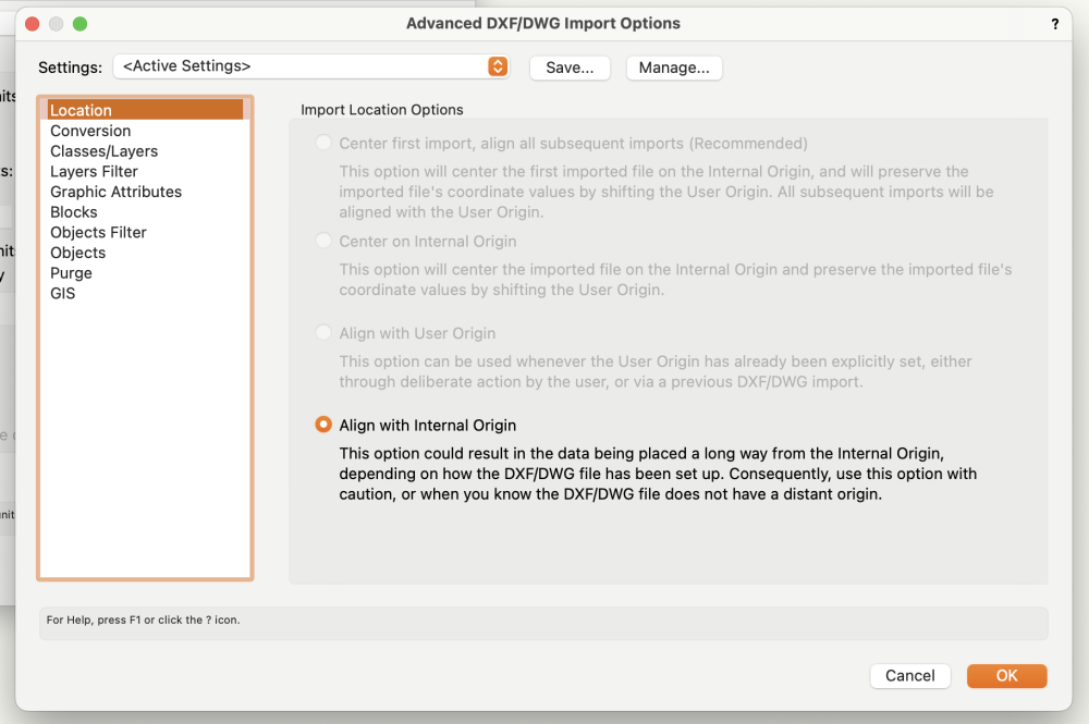
What original DWG? This is a georeferenced template file. But if I import a georeferenced DWG into it the import settings automatically default to the 'Align with Internal Origin' option + the imported geometry will be correctly located relative to the User Origin. Which is precisely what I want. Then once I've designed the building I can give the surveyor the coordinates for the foundations + he can mark them out on site. Because we're all working to the same coordinate system.
-

-
My User Origin is aligned with the OSGB36 datum i.e. located south west of the Scilly Isles. My Internal Origin is in Norfolk...
-
No. My geometry is centred on the Internal Origin.
-
If you use Subtract Solids on a Wall you will turn the Wall into a Solid Subtraction which you generally wouldn't want to do. You can use a Door or a Window set to 'Opening' configuration though (to make a hole).
-
I thought the advice is to always rebuild your custom workspace from scratch each year rather than migrating it over (to exclude the risk of it becoming corrupted). It's a real pain to do but I was told it's not worth the risk...
-
Yes I think it just gives you a written record to refer back to when you manually recreate the workspace...
-
I'm pretty sure the text file is just for reference + can't be imported as such but I'd love to be wrong on that... I don't find it enormously useful to be honest. I keep screenshots of my workspace as well + find these more useful when it comes to recreating it.
-
Various issues, lot of crashing no clear reason, high memory usage.
Tom W. replied to Blinkglitter's question in Troubleshooting
Does this apply to XS as well or just full interiorcad? I just changed from demo version XS to proper paid version a few days ago + it says I'm on version F4.1... Should I be looking to update...? How? Thanks -
How to add a hatch to the Top/Plan View of a symbol?
Tom W. replied to Darin K's topic in General Discussion
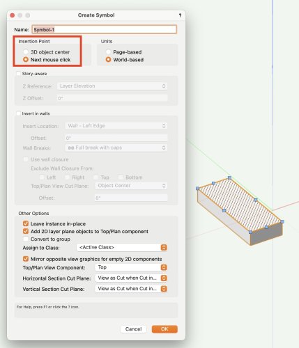
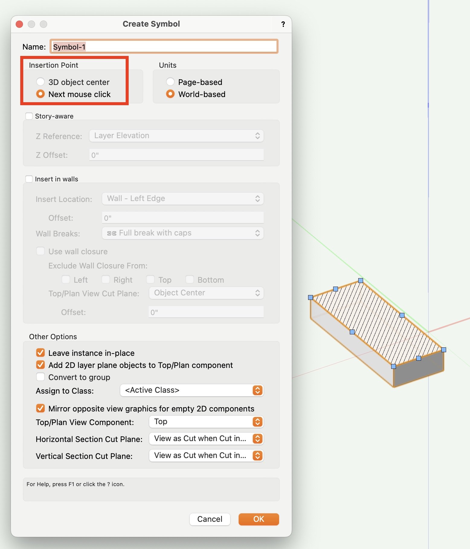
When you create a symbol you have two options for setting the insertion point: 'Next mouse click' allows you to place it precisely where you want + this is the option you used. '3D Object Centre' (or 'Plan projection centre' if you are in a Top/Plan view) does it automatically + places it in the centre of the object. Just to explain what the circle/cross symbol was!