


MartinBlomberg
-
Posts
199 -
Joined
-
Last visited
Content Type
Profiles
Forums
Events
Articles
Marionette
Store
Posts posted by MartinBlomberg
-
-
13 minutes ago, Joe Golden said:
I just made some using the truss tool, make a flat truss. When it was done, I changed it to a group and edited the profile for the main chords to make the rectangular instead of square.
Good strategy! Thanks!!
-
Hi all!
I'm drawing an arena at the moment and I'm trying to add some cable trays, "cable ladders" or whatever you call them, in the roof grid. Is there a tool for this or a workaround somehow?Something like this 😃

Thanks all!
-
On 7/31/2020 at 12:39 PM, Tamsin Slatter said:
Yes, as it's now a pure 3D object, it does not have an automatic 2D appearance. You can create the 2D view that you want, using either of the following methods:
1. Draw over the top, with 2D objects, then fill and class those as you desire. Select all, including the extrude, and run Modify > Create Symbol. This will create an object that has both 2D properties and separate 3D properties.
2. Select the Extrude, and run the Create Auto Hybrid command. This will automatically generate the 2D view for you.The Auto Hybrid command is in different places in different workspaces, but if you hunt through the menus, you'll find it.
Thank you Tamsin for helping out!
I'll try that one out, but still... For me this whole procedure seems a bit upside down. I mean, to have two different options that claims to be able to can change the appearance of the object, the Render tab in the OIP and then the Attributes pallette. But they won't do the trick this time. Might be me, I'm more then sure, but just seems a bit off, that's all.
Thanks for all support!
-
On 7/28/2020 at 12:54 AM, Taproot said:
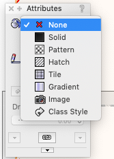
@MartinBlomberg If no colors are changing, then make sure that the fill in your attribute pallet is set to "solid" for the object (not "none").

@Boh I thought that OpenGL rendering was available for non-renderworks users. In which case, you would access the rendering mode via the Menu: View>Rendering>OpenGL
... after assigning a texture to the object.
Yep, I've set it to "Solid" and disabled the texture in the OIP->Render->Texture so it now says "None".
Still hollow in Top/Plan. Is this the way it's supposed to be?
Thanks all!
-
On 7/25/2020 at 6:21 PM, Pat Stanford said:
If the object is hollow (No Fill) when you extrude, you will get the sides only and no top/bottom surfaces.
Without Renderworks I don't think you will be able to use textures, so you will have to use colors only.
Thanks Pat! Alright, so do I need to change to only colours?
When I do that it doesn't change a thing, unfortunately...
-
13 minutes ago, Boh said:
Images are only for 2d. You can either use a solid fill with a colour to get different colours or better use a texture. Do you have renderworks? Textures are for 3D work. You can make a texture from an image.
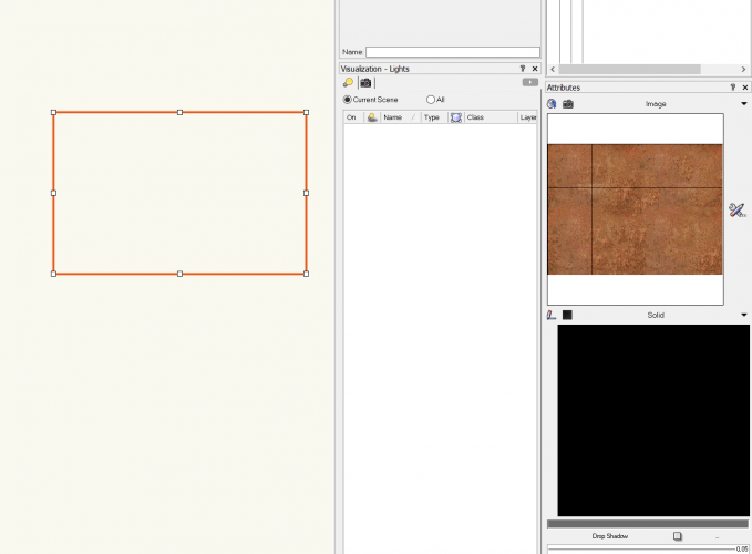
Thanks! I shifted to Top/Plan but it's just hollow. See image bellow.
Unfortunately I don't have Renderworks. How do I access the textures easily?
This workflow seems quite off for me, thanks for the help!
Martin
-
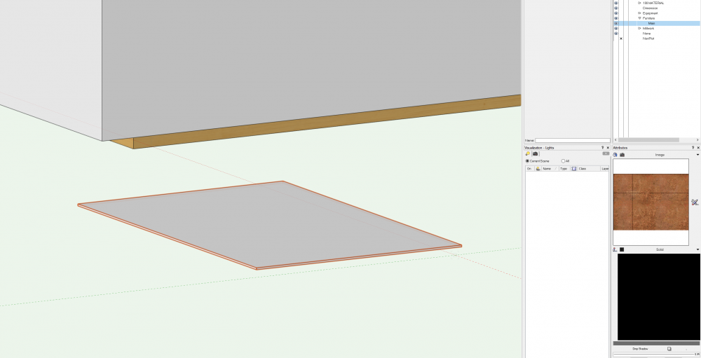
Ok, this is me on a Saturday morning, can't figure out what I'm doing wrong.
1. Draw a recangle
2. Extrude
3. Change layer and class (I don't use Class styles)
4. I want to change the appearance of the extruded object, but it won't change.
What. Am. I. Doing. Wrong? See image for reference.
Thank you all!
-
58 minutes ago, Hans-Olav said:
If you want to see them all together they must be in same scale. However you can make a sheet layer with viewports and have them in different scale
Thanks man! Works like a charm! 😃
-
 1
1
-
-
18 minutes ago, Hans-Olav said:
Hi
Are your layers of different scale?
Ah, yes they are. Is that the problem?
-
Hi,
Posted on a FB group as well, but I guess this might be faster 😃
Anyone knows why the PDF disappears when I activate the other layers? And why does everything else disappears when I activate the PDF?
Please see attached video for reference. Thanks!
-
Hi @Pat Stanford and @Eric Chase
I'm having the same issue as you Eric, (didn't download the file yet due to very slow download speed) but I'm trying to work with some referenced dwg-files in my VW project and it's just silly how slow things are. Feels like a computer from 2001. I've sent a bug report via the "form" but haven't heard anything back yet (this was over 2 months ago). I've been working with AutoCAD, Revit and Fusion 360 but VW is by far the least responsive software that I've experienced in this category. Worth mentioning is that I've worked with these dwg files flawlessly in Autocad with a computer that wasn't suppose to manage software like Autocad.
Now I'm on this machine:
Intel Core i7-4770K CPU @ 3.5Ghz
16GB RAM
SSD Disk
Nvidia GeForce RTX 2070
3840x2160, 60Hz
Thanks!
-
6 minutes ago, Pat Stanford said:
I think you are going to have to change your habits. 😉
As far as I know, if you are working in Rotated view and are in a view other than Top/Plan, hitting the Zero key switches you back to the Rotated Top/Plan view.
If you are already in Rotated Top/Plan, the Zero key switches you back to Unrotated Top/Plan.So you either need to train yourself to not hit Zero when you are in Rotated Top/Plan, or you need to learn the keyboard shortcut for Previous View so you can get back to the Rotated view easily. In the default workspace that shortcut is Command, Shift - Comma (,). On a US keyboard you can think of this as Command - < (less than)
Aha, alright.
The funny thing is that it sometimes, even though I'm in a different view, gets me back to the original view.
But I'll check into the new habits 😃
Warm regards and many thanks!!
-
On 5/12/2020 at 10:23 AM, markdd said:
It only works for moving objects (which was in your original post)
This quick video shows the process I use. I have put the extension line and smartcursor settings up as well.
Hi,
Thank you so much for this! Totally make sense, much appreciated!
// martin
On 5/12/2020 at 10:23 AM, markdd said: -
Hi,
I'm doing a drawing with my plan rotated -22 degrees to make GIS image horizantal to my design.
When I push the Num 0, more or less every second time VW gives me the -22 degree look, and every other time the 0 degree look.
How do I make my -22 degree look stick to my design until I say otherwise?
Thanks!
-
15 hours ago, Pat Stanford said:
You can change datum points in the middle of a move. Start at your initial point and get a datum. Tab into the flyout data bar and enter your 950mm in the X field and hit tab. You should get a red vertical line 950 mm from the datum. Mouse over to where the red line intersects your wall bottom. Hit the G key to move the Datum to the intersection of the wall and the red line. Hit tab to get into the flyout data bar. Tab into the Y field and enter your 1500mm. You should now have as datum point and crossed red lines at the point you want to move to.
You may not even need to use the G key to set the datum. It may set for you automatically.
OK! Great news! I'll try that straight away. Many thanks!!
-
15 hours ago, markdd said:
The Move by points tool using the 3rd mode will allow you to move objects from a reference point by a specific distance.
If you then want to add a certain value to the height, say 1500mm, then just add +1500mm to the height field in the object info palette for the Window. Vectorworks will do the calculation for you.
.
I've tried that and it kinda does the trick, but it only works if I want to move something, not draw, right?
Thanks!
-
Thank you Pat for your answer. I did some (quite short, to be honest) research and didn't find really the same thing as there is in AutoCAD.
I use smart points all the time, but I want to measure from a specific point to a specific distance. Say I want to place a window 950mm from a wall and then move it 1500mm from the ground, what's the most simple way to do that?
Real newbe question I guess, but still need it 😃
Thanks again!
-
I'm coming from AutoCAD and can barely survice without the "Measure from" or "Place between two points".
How do I do that in VW?
Say I want to place a window exactly between two points, or if I'm putting an object at a specific distance from another object?Probably a super simple solution, but I can't get how to do it.
Thanks!
-
Hi,
I'm really trying to like the workflow with the GIS feature in VW, but I'm struggling to be honest.
I always get "Image download failed" and nothing happens if I change the resolution or service.
Any clue why this is?
Thanks!
-
Hi,
Super basic question I guess, but I can't seem to find the reason why this doesn't work.
I'm trying to add a slab to my walls, but nothing shows up. Please refer to short clip I added.
Warm regards and thanks all!
Martin -
19 hours ago, bgoff said:
@MartinBlomberg No need to be nasty, We ALL will help! 😂
Don't you hate when you send something and realize later what you sent.
Anyways, my guess is that the image needs to be scaled to the appropriate size or it could be a layer scale issue. The exact problem is difficult to diagnose without seeing the issue at hand. Feel free to PM me your file and I would be happy to take a look. Once I see the issue I will let you know how to solve it. I will also repost here for others to understand the solution (I will not post you file).
Thanks for understanding my typo 😃
And also, thank you for your support!
You've got the file now on PM. Looking forward to see what I'm doing wrong.
Warm regards! // martin
-
NO! Autocorrect! Haha, Thanks ALL!!!
-
Hi,
It's my first and I'm quite new to VW, so bear with me =)
I'm doing a site plan and have the GIS image ready and all. But, the measurements doesn't match.An ordinary parking lot is 10.8m but are usually around 5m here in Sweden. The units are set to mm and everything should be fine as far as I'm concerned.
What am I missing here?
Thanks ass!


No symbol in Twinmotion
in Rendering
Posted
Hi all,
I'm exporting a Cinema 4D file from VW containing a sport arena. I made a symbol of the sport floor, with all the lines for off side and so on.
When I import this as a 3d-file into Twinmotion the symbol doesn't appear.
Any clue why this is?
Thanks!