bc
-
Posts
1,151 -
Joined
-
Last visited
Content Type
Profiles
Forums
Events
Articles
Marionette
Store
Everything posted by bc
-
Christiaan. That did it! Thanks a lot. Sheesh. You'd think it would be simpler than this.
-
-
Thanks Pat but no, the active class is None. I should add that in Plan it will disappear when classed off. In Top Plan, it remains visible. Maybe something to do with wireframe vs OpenGL? And yes the trim does disappear in 3D. And I can't class them off in viewports set to top plan
-
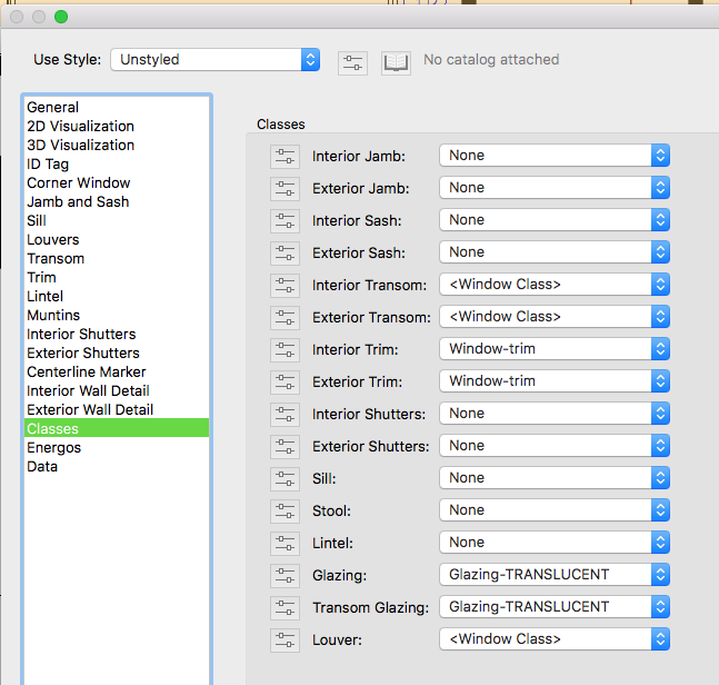
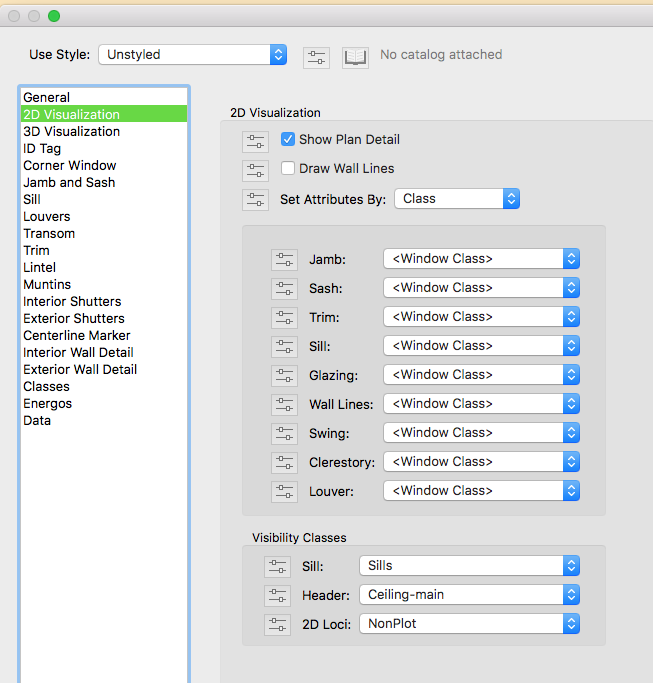
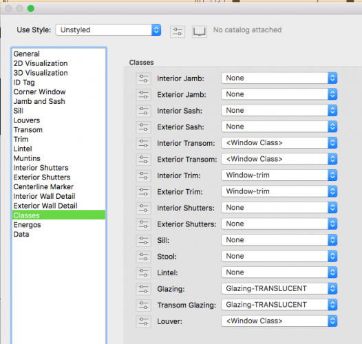
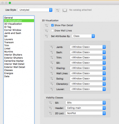
So I have my window in wall with it's trim set to on and placed in a class via the settings dialog. I want it to show in elevation but not in plan. I can have it show or hide in elevation but turning the class to invisible has no effect in top plan. The trim still shows. How can I get the trim to disappear in top plan? thanks bc
-
I just now opened it in 2019 and the condition persists. I subscribe to 2020 but haven't even installed it yet (unimpressive) so I am not able to see if it persists. I suspect it does. I wish it didn't.
-
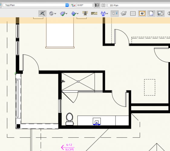
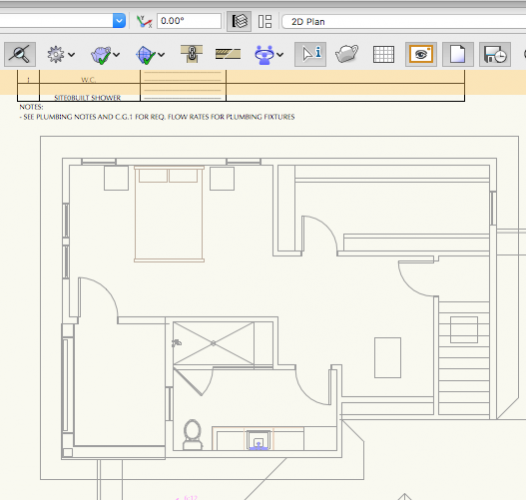
ArtV, the top shot shows Design Layer A with the bathroom in the center with the sink counter and walls etc solid in top plan view the bottom shot is a viewport of the Design Layer A on a different design layer. In that viewport, the Design Layer A visibility is set to grey. I don't want the counter top and walls to be wireframe.
-
I wish there was the option to show greyed layers as transparent (status quo) or to show them as in top plan , where solid objects such as floors/walls etc appear solid. I believe the latter should be the default.
-
Thanks, The layer that is greyed is a layer set to top plan. Nothing viewed in 3D. There are 3D objects but they should look like they otherwise do in top plan only greyed. Guess I'll wish list it.
-
Why is it that my greyed layers show transparent? Walls, floors,extrudes do not look like they do in ungreyed regular plan view. They show as wireframe. I want that, when the layer is greyed, it looks like it usually does only greyed. Not transparent. Is there some setting I'm missing or do I need to wishlist this?
-
THANKS A LOT ANDY. That should do it! Didn't think that they wouldn't be placed on their design layers.....
-
THANKS ANDY, When I go there, open the Detail Marker file, there is nothing there. All layers and classes are visible and set to modify and I select all. And there is nothing at all in my User Detail Marker file. What might I be doing wrong? I'm on 2018 BTW, sorry.
-
I suppose that I just can't get there from here.
-
How do I change the line weight for the Detail Callout Marker? I know how to change the leader line but what about the marker object itself? They are printing way too lightly. Thanks bc
-
Well if you are needing a stair object, you have a tough learning curve ahead of you. It can be infuriating. Archicad hits this one out of the park.
-
Thanks everyone, I fixed it. I moved my Design Layer back down to 0 and then moved the DTM up 1300 ft. Then updated. Now the contour labels are correct. I appreciate all the help. Bradley
-
That's what I thought. They don't change.
-
I think you've nailed it down for me Boh. I created the DTM @ 0'=0" and it only has 80' of elevation changes. I then moved it up 1,300 ft with the move command. Still reads original contour markers. So I guess I should move the dtm back down to 0 by moving the DL, enter the edit site data and move all the data points up to where they should be? I like the fact that I can trim the bottom off so I won't be left with a towering DTM. Or should I just start over and create the DTM anew? Thanks for your help!
-
It was originally created @ 0'-0" on it's design layer. It has been moved in the z direction by virtue of moving the design layer it resides on.
-
All the contours were generated with stake objects set to the elevations as provided by surveyor.
-
How can I get my contour labels on my Site Model to read correctly? The 70'-0" contour should read 1,420 ft. The 70 ft label is as if it were referencing the bottom most contour data. I should add that the 70 ft contour does reside @ 1,420 ft elevation. Thanks

-
All right! Thanks for all that everyone. I'll give it a go and try both methods.
-
This is pretty annoying. Darn near impossible for me to select site model modifiers on a site model...even in wire frame. The model always takes priority. What is the best way to select site modifiers on a site model? Thank you. bc
-
Also Grid Bubbles need to show up on elevation viewports as annotations like section markers in plan....be able to choose which block shows up so conflicts don't arise..
- 1 reply
-
- 1
-

-
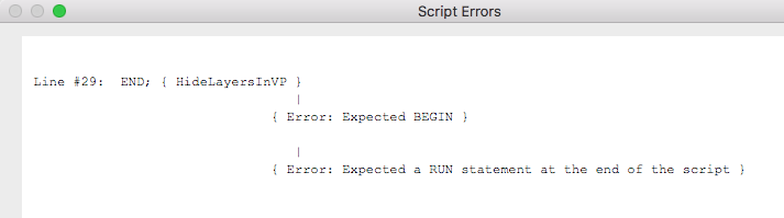
@Amorphous - Julian I can't get this to open in 2018 or 2019. Says file is too old or corrupt, etc. What is your recommended proceedure for utilization of this script? Thanks alot! bc OK So I copied the script into my scripts palette and when I run it is says: Not privy to scripting, I don't know where to go from here. Any help? NOW I HAVE IT WORKING. I failed to copy the absolute entire portion of the script from the file. THANKS JULIAN!!!

-
I wish for correct mapping on doors, again
bc replied to bc's question in Wishlist - Feature and Content Requests
No joy, rDesign. @Christiaan and others. I anticipate my wish to be fruitless, but my question still begs an answer: Why can't VW handle this? Certainly there must be some nightmare coding issue? It would be somewhat forgivable then, but to think that after all this time, this little thing (and others) can't get attention is perverse. If it was a coding issue, why utilize a code that creates such an issue? So someone initially says, "We can't texture doors correctly with this code but that is fine because we CAN make extrudes and walls and model solids that emulate M.C. Escher. " I know Matt Panzer and a few others check in occasionally and kudos for that morsel but now that we're back to a community board left to fend for itself? It's disheartening. Maybe if I knew my annoyance would lessen. So to anyone in VW land, if you happen to be listening, I am asking: Why can't VW handle this?